Note: Descriptions are shown in the official language in which they were submitted.
2082877
,
Subrack with Clamping Dev;ces
The present invention relates to a subrack with clamping
devices as set forth in the preamble of claim 1. Such
subracks serve to mount units, preferably printed c;r-
cu;t boards, which are releasably fixed in the subrack
by means of at least one clamping device each.
Such a subrack with clamping devices is disclosed in
DE 29 20 ~68 C2~ The sidewalls of the subrack, which is
des;gned as an enclosure, contain guide grooves of U-
shapedsection. Each guide groove ;s fitted w;th a clamp-
ing dev;ce consist;ng of two parallel,spaced-apart flat
bars which are pivotally interconnected by a number of
inclined bridge members. By means of an actuating screw
connected with the housing, one flat bar is longitud;nally
movable relative to the other flat bar, which ;s supported
by the enclosure and in the guide groove. This produces
a clamping force acting ;n the d;rection of the printed
circuit board.
.
DE-OS 19 53 363 discloses a tensioning device consisting
of several thrust pieces which occupy essentially the
whole length of a guide groove and have wedge surfaces
arranged at an angle to the longitudinal axis. The
thrust pieces are movable divergingly by means of an
2082877
actuat;ng screw, so that, if the guide grooYe is ~ide
enough and the tensioning device is mounted centrally
there;n, a printed circuit board can be clamped between
the tens;on;ng device and each of the Lateral groove walls.
It is the object of the invention to provide a subrack
hav;ng a clamping device of low o~erall height ~herein
the clamping device requires only a minimum clamping area
at the pr;nted c;rcuit board to securely fix the latter
in pos;t;on. Nevertheless, the clamping is to have a
relatively high res;stance to shock and vibration. This
object, according to the invention, is attained by the
features set forth in claim 1. Further advantageous fea-
tures of the invention are defined in the subclaims. The
invention has the advantage that all requirements of its
object are sat;sfied, and that, in addition, the clamping
device consists of only very few, s;mple component parts
which can be made with tolerances as are commonly re-
quired in precision mechan;cs, and can be assembled w;th-
out difficulty. Therefore, the clamping device can be
fabricated very econom;cally, i.e., at relatively low
cost. No additional mounting parts are necessary. Although
only an extremely small clamping area is needed at the
printed circuit board, the high contact pressure achievable
with the clamping device permits a ground connection as
well as good thermal contact with low electrical and
thermal contact resistance to be established between the
subrack and suitably metallized areas on the printed cir-
cu;t board. Further advantages are mentioned in the de-
scription.
The invention will now be described in more detail with
reference to an embodiment illustrated in the accompanying
20~28~7
drawings, ;n which:
Fig. 1 is a longitudinal sect;on of a subrack f;tted
w;th several clamping devices;
F;g. 2 ;s a front view of part of the subrack of
F;go 1 with pr;nted c;rcu;t boards f;xed
therein;
Fig. 3 is a side view of a clamping device as
shown in Fig. 1;
Fig. 4 ;s a top view of the clamping dev;ce of
F;g. 3, and
Fig. 5 ;s a front view of a subrack assembly with
several gu;de grooves for rece;ving a
corresponding number of clamping devices.
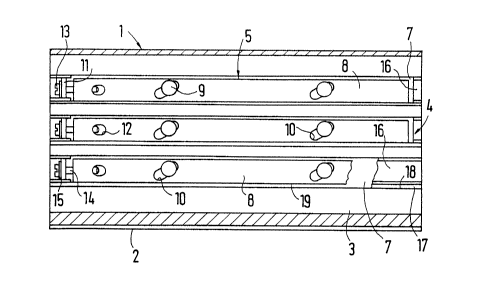
In the drawings, the subrack ;s designated 1. In the em-
bodiment shown, the subrack ;s designed as an enclo~
sure which has a tubular ~iddle portion 2 of essentially
rectangular section and whose open ends are closable
by cover plates or caps (not shown). The middle portion 2
preferably made of aluminum, is, for example, a die-cast
part or an extruded shape cut to length. It may also con-
sist of two shaped rails fitted together. The subrack 1
may also be of an unenclosed design, of course,
in which essentiaLly only shaped bars are attached to each
other in horizontal and vertîcal positions so as to form
a rectangular-parallelepiped-shaped frame rack having guide
bars ly;ng opposite each othern
2082877
-- 4 --
As shown part;cularly in F;y. 5, the middle portion 2 ofthe
enclosed subrack 1 has guide grooves 4 in at least one side-
wall 3, but preferably in two opposite sidewa(ls, with
the open sides of the grooves facing each other. In the
unenclosed, frame-shaped version of the subrack 1, each
guide rail has at least one such guide groove 4. The
guide groove 4 has an undercut, T-like cross section and
ser~es to receive a clamping device 5 and to guide and
locate the longitudinal edge of a printed circu;t board 6
whenthe latter is being fixed in position (Fig. 2~.
The clamping device 5, shown separately in Figs. 3 and 4,
consists essentially of a holding rail 7 and a thrust
strip 8 slidably mounted thereon, which contains at least
two slots 10, through each of which extends a pin 9 of
the holding ra;l 7 and whose longitudinal axes make an
acute angle with the longitudinal axis of the thrust
strip 8. The hoLding rail 7 is a sheet-metal strip of
rectangular section, e.g., a sta;nless-steel strip, pro-
~ided at one end with a rectangularly upwardly bent sup-
porting tongue 11. This supporting tongue 11, which is
sLightly narrower than the thrust strip 8, contains an
oblong hole extending parallel to the bending edge.
The thrust strip 8, which rests essentially flat on the
holding rail 7, also has a rectangular cross section.
It is, for example, a length of a semi-finished
product, e.g., flat aluminum, or a die-cast part and is
approximately twice as thick as, but narrower than, the
holding rail 7. The end of the thrust strip 8 pointing
toward the supporting tongue 11 of the holding rail 7
2082877
-- 5 --
contains a tapped hole which extends from the end face to
an opening 12 in the thrust strip 8, said opening 12
serving to facilitate the formation of the tapped hole.
The latter contains the shank 14 of an actuating screw
13 inserted from outside through the oblong hoLe in the
supporting tongue 11, such that between the support;ng
tongue 11 of the holding raiL 7 and the thrust strip 8,
there is st;ll a sufficient d;stance for displacement.
The actuating screw 13 is a commercially auailable stan-
dard screw with a right-hand thread. If the clamping de-
vice 5 is to be adapted for frequent use, a compression
spring (not shown), serving as a restoring element, and/
or a retaining washer (not shown) will be provided on
the shank 14 between supporting tongue 11 and thrust
strip 8.
ay turning the actuating screw 18 clockwise, the thrust
strip 8 is moued both in the direction of the supporting
tongue 11 and transuersely to the holding rail 7, with
the screw shank 14 sliding in the oblong pole and the
screw head alon~ the outside of the supportin~ ton~ue 1?, the screw
head being preferably underlaid with a washer 15~ To achieve opti-
mum clamping action, the angle between the longitudinal
axes of the slots 10, which are arranged parallel to each
other, and the thrust strip 8 is preferably 30. The pins
9, which extend through the slots 10 of the thrust str;p
8, are spaced relatiuely far apart and are fastened
centrally in the holding rail 7, e.g., by riueting or
flanging the hollow pin end. The pins 9 haue a flat head
whose d;ameter is greater than the width of the slot 10,
and prevent the thrust strip 8 from lifting.
The T-like guid~e grooue 4 in the subrack 1 and the clamp-
ing device 5 are adapted to one another in cross section,
2082877
-- 6
such that the latter can be inserted from an open end in-
to the guide groove 4 w;th slight pressure~ The long;tu-
dina( edges of the hoLding ra;l 7 are recei~ed and
guided by the Lateral undercuts, while the thrust strip
8 is recei~ed in the open portion of the guide groove
4 ~ith relatiYely much lateral play. In order that the
cla~ping deuice 5 can hold itseLf in the guide groove 4
in a self-locking manner, the hoiding ra;l 7 ;s sl;ghtly
bent in one or both end regions between pin 9 and ra;l
end, so that it is ~ertical(y resilient and compensates
for thickness to~erances of both the holding rail 7 and
the guide grooYe 4. Lf the pins 9, as can be seen ;n the
embodiment shown in the draw;ngs, are so fastened in
the holding rail 7 that material projects at the underside,
the groo~e bottom has a sufficient~y large depression 16,
which can be omitted if the pins are fastened in a manner
requiring no project;ng mater;aL. In any case, one side-
wall of the guide groove 4 has a steplike recess ~7 which
widens the groo~e opening and forms the receptacle proper
for the printed circuit board 6, since its bottom guides
the Longitudinal edge of the printed circuit board 6
during insertion, while its side serYeS as a locating
surface 18 for the board (Figs. 1 and 5).
If the guide grooYes 4 are equipped with unoperated clamp-
ing deYices 5, and printed circuit boards 6 are inserted
loosely into the subr3ck 1 from an open side, the printed
circuit board 6 will be f;xed in position by turni~g the
actuating screws 13, whereby narrow edge regions of the
printed circuit board 6 are each firmly clamped between
one long side 19 of the thrust strip 8 and the complementary
2082877
locating surface 18 in the guide groove 4. As the actuat-
ing screws 13 are rotated, causing the thrust strip 8 to
bepressed against the printed circuit board 6, the hold-
ing rails 7 are so firmLy clamped in the guide grooves
4 that the cLamping devices 5 are securely held therein
and the printed circu;t board 6 is held in a shock- and
vibration-proof manner. By turning the actuating screws 13
counterclockwise, the fi~in~ is released.
Tolerances acting in the direction of the pressure exerted
by the cLamp;ng devices 5, wh;ch result during the manu-
facture and formation of pins 9 and slots 10 and are aLso
present in the profile of the guide groove 4, are com-
pensatedforby a spec;a~ shape of the hoLd;ng raiL 7.
For th;s reason, the narrow long sides of the hoLding rails 7~
starting from a short center portion w;th paralle~ long sides,
extend sLightLy conically toward both ends. Under clamping
pressure, this design permits a sLight elastic deformation
of the hoLding ra;L 7, wh;ch causes part;cuLarly f;rm ten-
sioning ;n the gu;de groove 4 and simultaneously ensures
that the thrust strip 8 ;s pressed aga;nst the printed
circuit board 6 along its entire length with approximately
equaL force. The tensioning also prevents the clamping de-
vice 5 from loosening, and the clamping device needs only
an extremely small clamping area to secureLy fix the
printed circuit board 6 in position. If, for example, the
holding rail 7 and the thrust strip 8 are 2 mm and 4 mm
thick, respectively, and the distance between undercut and
~ecess 17 of the guide groove 4 is ~.5 mm, only a 2.5-mm-
wide stripe is needed at the printed circuit board 6 to
securely fix the latter in position. This low area require-
ment permits a high degree of utilization of the printed
circuit board 6, which can be equipped with components both
on one side and on both s;des. The component space 20 is
indicated in Fig~ 2 by dash-and-dot lines.