Note: Descriptions are shown in the official language in which they were submitted.
WO 9~/17698 Pcr/US91/03395
2~830~3
"Steerab1e Gllide ~Lre for nl~ular Car~ulation". - -
S . --
, ,
FIELD OF THE INVENTION
The invention relates generally to flexible guide wires for
cannulation of tubular or vascular organs to be used alone or in
conjunction with catheters or endoscopes.
:`
BACKGROUND OF THE INVENTION
When medical procedures or operations require cannulation of a
tubular or vascular structure or organ in the human body, guide wires
. are typically employed. Due to tlle flexibility, softness of the tip and
narrow gauge of a typical guide wire, it is advantageous to first insert a
;., guide wire into the organ to help position a larger diameter catheter or
other instrument needed for the procedure. Some organs have
characteristics which make the use of conventional straight guide wires
difficult. For exarnple, standard techniques using conventional guide
wires for endoscopic cannulation of the cystic duct are not entirely
satisfactory.
The cystic duc~ connects the gallbladder and the common bile duct.
The cystic duct, however, has unique characteristics which distinguish it
from other tubular organs. The mucous membrane lining the interior
of the cystic duct has several crescentic folds commonly called valves of
Heister, the exact function of which is still unclear. Typically, the
number of folds ranges from five to twelve. The folds are directed and
obliquely round having an appearance of a continuous spiral valve. The
, .
. . , . , - . . i . .
, . :, . .
Wo slt17698 P~r/ussl/o33~
2a83~3
presence of these spiral folds, in combination with the tortuosity of the
cystic duct, makes endoscopic cannulation of the cystic duct extremely
difficult. The valves of Heister impede the introduction of surgical
instruments and are prone to lacerations. There is a great need for a
device which makes eannulation of the cystic duct both safe and easy for,
among other things, the diagnosis and treatment of gallstone disease.
There has been extensive researeh and development eommitted to
the design of a suitable guide wire for use in eonjunetion with a
preshaped eatheter system to allow the eystic duct and gallbladder to be
reliably catheterized, retrograde, using an endoscope or other apparatus.
Because of the unique structure of the cystic duet folds, sueeessful
eatheterization of the eystie duet and the gallbladder during endoseopie
retrograde proeedures is obtainable only when favorable anatomieal
situations exist. Because of the difficulty in negotiating the eystie duet,
it is only exceptional eases where seleetive eatheterization can be
aehieved using conventional guide wires.
Frimberger et al., Endoseopy 15:359 (19~3), was among the first
to report attempts to routinely eannulate the gallbladder with the aid of
a speeial endoseope. The system was extremely eomplieated, however,
and did not facilitate reliable cannulation.
One of the most advaneed guide wire and eatheter systems for
eannulation of the gallbladder and eystie duet was diselosed in Foerster
et ah, ~y 20:30, 33 (19~). Foerster et ah discloses a speeially
made thin steerable guide wire with a straight, 6 em long soft distal tip.
In Foerster et al., the thin, straight steerable guide wire is inserted into
a pre-shaped eatheter pre-positioned near the opening of the eystie duet.
The guide wire is then advaneed through the eatheter and into the cystic
duct. Onee positioned in the eystie duet, the thin, straight guide wire
must be earefully manipulated to suecessfully traverse the valves of
'"".
.
. . . . .. . . . . . . . .. . . . .
WO 91/176g8 PCr/US91/03395
-3- ~l38c~a~3
Heister. The use of a conventional straight guide wire, as taught in
Foerster et al., may result in the guide wire catching on the cystic duct
folds, impeding its forward progress and causing injul~ to the duct.
Hence, it is an object of this invention to provide a guide wire
designed to be used in conjunction with a preshaped open hook
configuration catheter system, as an example that described by Foerster
et al., for endoscopic retrograde cannulation of the gallbladder. The
unique configuration of the guide wire invention is the result of careful
research into the anatomy of the cystic duct and the valves of Heister.
The invention comprises guide wire having a unique construction which
provides forward traction upon application of torsional force along the
guide wire while at the same time employing an ultra-low friction surface
which reduces friction between the guide wire and a catheter when used
in conjunction. ~ ~-
SUMMARY OF THE ]NVENTION
Generally, the invention relates to a flexible, steerable guide wire
for retrograde or antegrade cannulation of tubular or vascular organs
such as the cystic duct. The guide wire has a proximal end and a distal
end, the distal ênd having a unique spiral tip for negotiation of the cystic
duct. More specifically, the distal end of the guide wire is formed with
a plurality of coils forming a helix. The coils are formed so that the
helix has an outer diameter greater than the diameter of the distal end
of the guide wire when the helix is in the free position. Because the
guide wire is flexible, the helix can be straightened or elongated when
subject to external forces, such as those induced when the guide wire is
passed into a narrow catheter, and the outer diameter of the helix can
:.
.
~W~0~76~9~ P~lUS9t/03395
be reduced to the point where it approaches the diameter of the guide
wire shaft at the distal end.
At the proxirnal end of the guide wire, means for manipulation of
the guide wire are removably secured to facilitate transmission of
i 5 torsional forces along the longitudinal length of the guide wire to help
steer the guide wire into a desired position. In one embodiment of the
invention, the guide wire has an ultra-low friction surface and is tapered
at the distal end to increase flexibility at the dista] tip.
BRIEF DESCRIPTION OF THE DRAWING
i ~
The accompanying drawings, which are incorporated in and form
a part o-f the specification, illustrate the embodirnent of the present
invention and, together with the description, serve to explain the
principles of the invention.
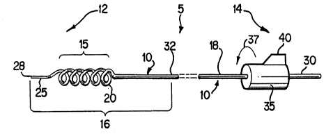
Figure 1 is a perspective view of the steerable guide wire for
cannulation of the gallbladder.
Figure 2 is a perspective view of the steerable guide wire inserted
into a preshaped common bile duct catheter so that the helix at the
distal end is straightened by the dimensions of the catheter.
Figure 3 illustrates the steerable guide wire negotiating the valves
of Heister located in the ostium of the cystic duct.
Figure 4 is an i~lustration of the steerable guide wire with a pre-
shaped catheter fitted over it and the helix at the distal end external to
the catheter.
Figùre 5 illustrates the steerable guide wire inserted into a flexible
catheter causing the helix to be straightened along the length of the
distal end of the guide wire. The catheter and guide wire are positioned
'.
;' ~
.. ..
WO 91/17698 PCr/US91/03395
~3~3
-5 -
in the common bile duct with the distal tip of the guide wire near the
cystic duct.
Figure 6 shows the distal tip of the steerable guide wire negotiating - .
the valves o~ Heister located in the cystic duct.
DETAILED DESCRIPTION S:)F A
PREFERRED EMBODIMENT OF THE INVENTION
`
Referring to Fig. 1, the steerable guide wire, designated generally
as (5), comprises a wire shaft (10) having a distal end (12) and a
proxirnal end (14). The guide wire (5) has a total length of between 50
and 900 centimeters. The distal end (12) of the guide wire (5) has a
plurality of individual coils (20) forming a helix (15) which, in the
preferred embodiment, terminates into a distal tip (25) and a soft
rounded end (28). To facilitate increased flexibility at the distal end, the
preferred embodiment of the wire shaft (10) decreases in diameter
throughout a tapered portion (16) near thç distal end (12) of the guide
wire (5). Of course, other structures can be used to accomplish
increased flexibility at the distal end, such as a step-down configuration.
Z0 A removable clamp (35) having steering means (40) can be secured
to the proximal end (14) of the guide wire (5). The removable clamp
(35) can be used to steer the guide wire (5) via transmission of torsional
and longitudinal force from the steering means (40) to the wire shaft
`' (10) along its length. The removable clamp (35) is positioned near the
proximal end (14) of the wire shaft (10) so that proximal surface length
(30) exists on the proximal side of the removal clamp (35).
In a preferred embodiment of the invention, the length of the
; guide wire (5) is 400 centimeters. The wire shaft (10) is shaped having
a cylindrical or other geometrically shaped cross-section and is made of
' .
.. . .
,~
~.j
WO 91 /I 7698 Pcr/vs9 l /03395
~8~3 -6-
a plastic or metal material having an ultra-low coefficient of friction on
its outer surf~ce. In a preferred embodiment, the wire shaft (10) can be
made from a metallic or plastic wire having a hydrophilic coating such
as GLIDEWIRET~ made by Terumo ~Medi-tech] of Japan, distributed
by Microvasive of Watertown, Massachusetts. Preferably, the guide wire
(5) has an outer diameter of 0.035 inches (0.89 mm) with a constant
taper along a tapered portion (16) at the distal end (12). The tapering
begins at the taper junction (32) where the outer diameter is 0.035
inches (0.89 mm) and ends at tlle rounded end (28) at tlle extreme distal
extremity of the guide wire (~) having a narrowed diameter of 0.021
inches (0.53 mm). The tapered portion (16) of the preferred
embodiment has a length of 30 mm when measured from the taper
junction (32) to the rounded end (2~). The taper junction (32) is
positioned 10 millimeters from the proximal end of the helix (15) in the
preferred embodiment. Due to tlle reduced diameter, the tapered
portion (16) allows the distal end (12) to have increased flexibility. The
narrower gauge along the the tapered portion functions to allow the
helix (15) to be slidably inserted into a catheter (50). When a catheter
(50) is disposed over the length of the guide wire (5), the helix (lS), due
to its flexibility, straightens or flattens out as depicted in Figure 2.
The helix (15) is formed USillg at least one coil (20). Different
embodiments having different numbers of coils (20) allow the user to
select the embodiment best suited for tlle individual patient. The
varying anatomical differences in patients may dictate any number of
coils forming the helix. In the preferred embodirnent, five coils (20) are
present. Each coil (20) in the preferrecl embodiment has an outer
diameter from I to 2 millimeters, with a distance of 1 to 2 millimeters
between each concentric coil (20), and the helix being 15 millimeters in
length. In one embodiment of the invention, a distal tip (25) is located
~ ... ' ~' -` ` , : , ' : . .. . . ..
WO 91/17698 PCr/US91/03395
7 2033~3
on the distal side of the helix (15) and terminates in a rounded end (28).
In the preferred embodiment, the distal tip (25) would have a length of
5 mm. However, in an alternative embodiment, the guide wire (5) would
terminate at the distal end with the heliY (15), and would not have a
S distal tip (25) as shown in Figure 1.
Referring to Figure 2, the wire shaft (10) including the helix (15)
is constructed of a flexible material having an ultra-low friction surface
(18) to allow the wire shaft (10) to slide easily through a catheter (50)
even when the helix (15) is straigl1tened or flattened due to the narrow
internal diameter of the cathetel- (50). When the guide wire (5) is used
in conjunction with a catheter (50), there must be minimal friction
between the guide wire (5) and the catheter (50). An ultra-low friction
surface may be applied to either the catheter (50) or the guide wire (5)
to minimize friction. Thel efore, in another embodiment of the
invention, the guide wire (5) will lack any ultra-low friction surface but
will be used with a catheter (50) having an ultra-low friction surface such
as TEFLON or similar material. In either embodiment, however, the
wire shaft (10) must be made of a material that provides good torsional
rigidity required for traversing vascular structures or tubular organs such
as the cystic duct.
The actual number of coils (~0) selected to form the helix (15) is
variable to allow different embodiments which can be used depending
on the anatomy of the patient and the organ to be cannulated. The
actual embodiment used would be that which provides enough forward
traction through organs such as the cystic duct without slipping while at
the sàme time minimizing friction within the catheter by keeping the
number of coils to a minimum. In the preferred embodiment, the coils
(20) will be constructed to spiral along the longitudinal axis in a
clockwise configuration.
WO 91/1769~ PCr/US91/03395
20c,30li c~
Referring to Figure 4, the guide wire (5) may be used with a
preshaped catheter (50) of propoltional dimensions. Figure 4 shows a
guide wire disposed in a pre-shaped catheter (50) having the heli~ (15),
which is located near the distal end (12) of the wire shaft (10), extended
out from the distal opening (54) of the catheter (50).
Figures 5 and 6 illustrate the invention in operation. In one mode
of operation, a typical endoscopic retrogade cannulation procedure is
performed on the patient using a ~hick, flexible, conventiona] guide wire
(a "first" guide wire) having an approximate length of 400 centimeters
and a diameter of 1 millimeter. This first guide wire is inserted into the
common bile duct (80). Over this first guide wire a pre-shaped catheter
(50) having an approximate length of 180 centimeters and a 7 French
gauge diameter is passed until the distal end of the catheter (50) is
"hooked" into the cystic duct opening (62).
The first guide wire is then withdrawn and the distal end (12) of
the steerable guide wire (5) is inserted into the pre-shaped catheter (50)
As the guide wire (5) is inserted into the catheter (50), the helix (15) is
significantly, but not totally, straightened as depicted in Figure 2.
Torsional (37) and longitudinal force can be applied to the
removable clamp (3S) located ~t the proximal end (14) of the guide wire
(5) until the distal tip (25) is advanced through the catheter and into the
cystic duct. The position of the removable clamp (35) can be adjusted
along the guide wire (5) to accommodate the requirements of the user.
At this point, tlle helix (15) is partially or completely outside of the
catheter (50) within the cystic duct (60). Rotational torque (37) is then
gently applied to the guide wire (5). In a preferred embodiment, the
torque is applied using the steering means (40) on the removable clamp
(35). As rotational torque (37) is applied, the coils (20) of the helk (15)
,.
. ' .
: , .
WO 91/17698 PCr/US91/03395
9 - ~0~3~'~3
catch between the spiral folds (valves of Heister) (70) and advance the
guide wire (5) along the folds (70) and into or near the gallbladder (95).
Once the guide wire (j) is within the gallbladder (95) or in the
desired position, the pre-shaped catheter (50) can be gently withdrawn.
S The guide wire (S) is then in proper position for advanced stages of the
procedure, for example to allow a mini-endoscope to be passed over it
and into the gallbladder (95) for diagnosis and treatment. Such a mini-
endoscope could be used to directly visualize the cystic duct (60) and
gallbladder (95) pathology, or facilitate the extraction of brushings or
biopsies from benign Ol malignallt gallbladder lesions.
In addition, laser Ol electrohydl olic probes could be passed directly
over the guide wire (S) or througll an endoscope to fragment gallstones
in the gallbladder. The guide wire (S) itself may be used to open a
previously blocked cystic duct (60) and allow for medical dissolution of
gallstones with or without adjuvant extracorporeal shock wave lithotripsy.
Furthermore, the guide wire (5), once positioned in the gallbladder (95),
can be used to facilitate the passage of a large S or 7 French gauge
catheter over it. This size catheter may be used to infuse a gallstone
dissolution agent and aspirate gallstone dissohltion products, sample
gallbladder bile directly for diagnostic or investigational purposes, or
inject contrast into the gallblatldel (95) to obtain a cholecystogram or air
contrast cholecystrogram.
Removal of the guide wire (S) is accomplished by reversing the
procedures explained above. Rotational force (37) is applied to the
steering means (40) located on the pro.Yimal end (14) of the guide wire
(5) in a reversed direction to negotiate the guide wire (5) back through
the cystic duct (60) and into tl!e common bile duct (80) without causing
trauma to the valves of Heister. The guide wire (S) and the catheter
(50) are then both removed from the patient.
.. :
;
., .
: , . . : , . . .. . .- . ~ -
WO 91/17698 PCr/US91/03395
2~3~3 -lo-
The foregoing description of tl-e preferred embodiments of the
invention has been presented for purposes of illustration and description.
It is not intended to be exhaustive or to limit the invention to the precise
form disclosed, and obviously many modifications and variations are
possible in light of the above teaching. For example, the guide wire (5)
may be configured having other than a cylindrical cross-section. The
embodiments were chosen and described in order to best explain the
principles of the invention and its practical application to thereby enable
- others skilled in the art to best utilize the invention in various
embodiments and with various modificatiolls as are suited to the
particular use contemplated. It is intended that the scope of the
invention be defined by the claims appended hereto.
.
... .
: '.
'
.. ~ ... , . . . -. - . ~ - ~ . . -