Language selection

Search

Patent 2083133 Summary

Third-party information liability

Some of the information on this Web page has been provided by external sources. The Government of Canada is not responsible for the accuracy, reliability or currency of the information supplied by external sources. Users wishing to rely upon this information should consult directly with the source of the information. Content provided by external sources is not subject to official languages, privacy and accessibility requirements.

Claims and Abstract availability

Any discrepancies in the text and image of the Claims and Abstract are due to differing posting times. Text of the Claims and Abstract are posted:

  • At the time the application is open to public inspection;
  • At the time of issue of the patent (grant).
(12) Patent: (11) CA 2083133
(54) English Title: CONTACT LENS CASE
(54) French Title: ETUI POUR VERRES DE CONTACT
Status: Deemed expired
Bibliographic Data
(51) International Patent Classification (IPC):
  • A45C 11/04 (2006.01)
  • A45C 11/00 (2006.01)
  • B65D 81/24 (2006.01)
  • A61F 2/16 (2006.01)
(72) Inventors :
  • IVES, RAY C. (United States of America)
(73) Owners :
  • IVES IDEAS, INC. (United States of America)
(71) Applicants :
(74) Agent: FINLAYSON & SINGLEHURST
(74) Associate agent:
(45) Issued: 1999-09-21
(86) PCT Filing Date: 1992-03-18
(87) Open to Public Inspection: 1992-09-19
Examination requested: 1996-05-14
Availability of licence: N/A
(25) Language of filing: English

Patent Cooperation Treaty (PCT): Yes
(86) PCT Filing Number: PCT/US1992/002241
(87) International Publication Number: WO1992/016123
(85) National Entry: 1992-11-17

(30) Application Priority Data:
Application No. Country/Territory Date
670,575 United States of America 1991-03-18

Abstracts

English Abstract


A contact lens case (10) having a container (12) for
liquid solution (22), a tray (14) which fits into the container
(12) and having a substantially flat portion (26) for the
contact lens to rest on and an annular beveled outer portion
(30) for retarding the outward movement of the lens. A dividing
perpendicular bar (32) extending upwardly from the top of the
tray (14) and serves both to separate the right lens from the
left lens and to act as a handle for lifting the tray (14). The
tray (14) forms apertures (34) adjacent to or in near proximity
to the bar and other apertures (44, 46) to form the letter "L" on
one side of the bar and the letter "R" on the other side. A
removable cap (16) forms ridges on its inside to prevent the
creation of suction between it and the concave side of a lens.


French Abstract

Boîtier de rangement (10) pour verres de contact, comprenant un récipient (12) contenant la solution liquide (22), un plateau (14) s'adaptant à l'intérieur du récipient (12) et présentant une partie essentiellement plate (26) sur laquelle reposent les verres de contact et une partie annulaire oblique (30) qui ralentit le mouvement des verres vers l'extérieur. Une barre perpendiculaire de division (32) s'étend vers le haut depuis la partie supérieure du plateau (14) et permet à la fois de séparer le verre droit du verre gauche et, utilisée comme une poignée, de soulever le plateau (14). Ce dernier comporte des ouvertures (34) adjacentes à la barre ou à proximité immédiate de celle-ci, ainsi que d'autres ouvertures (44, 46) formant la lettre ''L'' d'un côté de la barre et la lettre ''R'' de l'autre côté. Un couvercle amovible (16) présente des nervures à l'intérieur, afin d'éviter la création d'une force d'aspiration entre ledit couvercle et le côté concave d'un verre.

Claims

Note: Claims are shown in the official language in which they were submitted.


-7-

The embodiments of the invention in which an exclusive property
or privilege is claimed are defined as follows:
1. A contact lens case for containing a pair of contact
lens in a liquid solution, comprising in combination:
a container forming a substantially circular bottom
and a substantially upright wall for containing a quantity of
the liquid solution;
a substantially circular tray comprising a top and a
bottom, designed to fit into the container, loosely fitting
within the upright wall for easy removal;
a dividing perpendicular bar extending from the top of
the tray and separating the top of the tray into roughly equal
substantially semi-circular sections, each section forming a
substantially semi-circular flat top surface surrounded by a
substantially semi-circular inwardly bevelled outer portion for
retarding outward movement of the contact lens, each section
slightly larger than one contact lens of the pair wherein the
tray forms an aperture from top to bottom on each side of and
substantially immediately adjacent to the dividing perpendicular
bar, allowing most of the liquid solution to flow through said
aperture when the tray is being lifted out of the solution,
whereby the dividing perpendicular bar can serve as a handle and
wherein the top surface on each side of the dividing bar is
large enough for the contact lens to move transversely to said
dividing bar and along said flat surface when that lens is
resting convex side down on the top of the tray and the tray is
removed from the container.
2. A contact lens case according to claim 1 wherein the
substantially upright wall forms an inner surface and an outer
surface, the case further including a support member integral
with the inner surface of the substantially upright wall to
support the tray wherein the tray does not rest on the bottom of
the container and wherein the height of the dividing
perpendicular bar is less than one third of the diameter of the
top of the tray.


-8-

3. A contact lens case according to claim 2 wherein the
tray forms at least one aperture from top to bottom on one side
of the dividing perpendicular bar forming the letter "L" and at
least one aperture from top to bottom on the other side of the
dividing perpendicular bar forming the letter "R".
4. A contact lens case according to claim 3 further
including a removable cap to securely fasten to the container
for retaining the lens and solution within the container wherein
the inside of the cap forms ridges to prevent the creation of
suction between the inside of the cap and the lens.
5. A contact lens case according to claim 1 wherein the
tray forms at least one aperture from top to bottom on one side
of the dividing perpendicular bar forming the letter "L" and at
least one aperture from top to bottom on the other side of the
dividing perpendicular bar forming the letter "R".
6. A contact lens case according to claim 5 further
including a removable cap to securely fasten to the container
for retaining the lens and solution within the container wherein
the inside of the cap forms ridges whereby a contact lens will
not form a suction pocket with the inside of the cap.
7. A contact lens case according to claim 1 further
including a removable cap to securely fasten to the container
for retaining the lens and solution within the container wherein
the inside of the cap forms ridges whereby a contact lens will
not form a suction pocket with the inside of the cap.
8. A contact lens case for containing a pair of contact
lens in a liquid solution, comprising in combination:
a container forming a substantially circular bottom
and a substantially upright wall for containing a quantity of
the liquid solution;
a substantially circular tray comprising a top and a
bottom designed to fit into the container, loosely fitting


-9-

within the upright wall for easy removal;
a divider affixed to the top of the tray and
separating the top of the tray into roughly equal substantially
semi-circular sections, each section forming a substantially
semi-circular flat top surface surrounded by a substantially
semi-circular inwardly bevelled outer portion for retarding
outward movement of the contact lens, each section slightly
larger than one contact lens of the pair wherein the tray forms
an aperture from top to bottom on each side of and substantially
immediately adjacent to the divider, allowing most of the liquid
solution to flow through said aperture when the tray is being
lifted out of the solution and wherein the top surface on each
side of the divider is large enough for the contact lens to move
transversely to said divider and along said flat top surface
when that lens is resting convex side down on the top of the
tray and the tray is removed from the container.
9. A contact lens case according to claim 8 wherein the
substantially upright wall forms an inner surface and an outer
surface, the case further including a support member integral
with the inner surface of the substantially upright wall to
support the tray wherein the tray does not rest on the bottom of
the container.
10. A contact lens case according to claim 9 wherein the
tray forms at least one aperture from top to bottom on one side
of the divider forming the letter "L" and at least one aperture
from top to bottom on the other side of the divider forming the
letter "R".
11. A contact lens case according to claim 10 further
including a removable cap to securely fasten to the container
for retaining the lens and solution within the container wherein
the inside of the cap forms ridges whereby a contact lens will
not form a suction pocket with the inside of the cap.
12. A contact lens case according to claim 8 wherein the


-10-

tray forms at least one aperture from top to bottom on one side
of the divider forming the letter "L" and at least one aperture
from top to bottom on the other side of the divider forming the
letter "R".
13. A contact lens ease according to claim 12 further
including a removable cap to securely fasten to the container
for retaining the lens and solution within the container wherein
the inside of the cap forms ridges whereby a contact lens will
not form a suction pocket with the inside of the cap.
14. A contact lens case according to claim 8 further
including a removable cap to securely fasten to the container
for retaining the lens and solution within the container wherein
the inside of the cap forms ridges whereby a contact lens will
not form a suction pocket with the inside of the cap.
15. A tray for holding a pair of contact lens while being
lifted from a liquid, comprising:
a substantially circular top which forms a
substantially flat inner portion for the contact lens to rest on
and an inwardly bevelled outer portion for retarding outward
movement of the contact lens;
a bottom; and
a dividing perpendicular bar extending from the top
surface of the tray and separating the top of the tray into
roughly equal substantially semi-circular sections, each section
forming a substantially semi-circular flat top surface
surrounded by a substantially semi-circular inwardly bevelled
outer portion for retarding outward movement of the contact
lens, each section slightly larger than one contact lens of the
pair wherein the tray forms an aperture from the flat portion of
the top surface to the bottom of the tray on each side of and
substantially immediately adjacent to the dividing perpendicular
bar, allowing most of the liquid to flow through said aperture
when the tray is being lifted out of the liquid, whereby the
dividing perpendicular bar can serve as a handle and wherein the


-11-

top surface on each side of the dividing bar is large enough for
the contact lens to move transversely to said dividing bar and
along said flat top surface when that lens is resting convex
side down on the top surface of the tray and the tray is
exposed.
16. A tray according to claim 15 wherein the tray also
forms at least one aperture from top to bottom on one side of
the dividing perpendicular bar forming the letter "L" and at
least one aperture from top to bottom on the other side of the
dividing perpendicular bar forming the letter "R".
17. A tray according to claim 15 wherein the height of the
dividing perpendicular bar is less than one third of the
diameter of the top of the tray.
18. A contact lens case for containing a pair of contact
lens in a liquid solution, comprising in combination:
a container forming a bottom and a substantially
upright wall for containing a quantity of the liquid solution;
a tray comprising a top and a bottom, designed to fit
into the container, loosely fitting within the upright wall for
easy removal, wherein the top surface of the tray forms a
substantially flat inner portion for the contact lens to rest on
and an inwardly bevelled outer portion for retarding outward
movement of the contact lens;
a dividing perpendicular bar extending from the top of
the tray and separating the top of the tray into roughly equal
sections, each section slightly larger than one contact lens of
the pair wherein the tray forms at least one aperture from top
to bottom on one side of the dividing perpendicular bar forming
the letter "L" and at least one aperture from top to bottom on
the other side of the dividing perpendicular bar forming the
letter "R", whereby the dividing perpendicular bar can serve as
a handle and wherein the substantially flat inner portion on
each side of the dividing bar is large enough for a user to have
access to opposite positions of the edge of one of the lens when


-12-

that lens is resting convex side down on the top of the tray and
the tray is removed from the container.
19. A contact lens case according to claim 18 wherein the
substantially upright wall forms an inner surface and an outer
surface, the case further including a support member integral
with the inner surface of the substantially upright wall to
support the tray wherein the tray does not rest on the bottom of
the container and wherein the height of the dividing
perpendicular bar is less than one third of the diameter of the
top of the tray.
20. A contact lens case according to claim 19 further
including a removable cap to securely fasten to the container
for retaining the lens and solution within the container wherein
the inside of the cap forms ridges to prevent the creation of
suction between the inside of the cap and the lens.
21. A contact lens case according to claim 18 further
including a removable cap to securely fasten to the container
for retaining the lens and solution within the container wherein
the inside of the cap forms ridges whereby a contact lens will
not form a suction pocket with the inside of the cap.
22. A contact lens case for containing a pair of contact
lens in a liquid solution, comprising in combination:
a container forming a bottom and a substantially
upright wall for containing a quantity of the liquid solution;
a tray comprising a top and a bottom designed to fit
into the container, loosely fitting within the upright wall for
easy removal, wherein the top surface of the tray forms a
substantially flat circular inner portion for the contact lens
to rest on and an annular inwardly bevelled outer portion for
retarding outward movement of the contact lens;
a divider affixed to the top of the tray and
separating the top of the tray into roughly equal sections, each
section slightly larger than one contact lens of the pair


-13-

wherein the tray forms at least one aperture from top to bottom
on one side of the divider forming the letter "L" and at least
one aperture from top to bottom on the other side of the divider
forming the letter "R" and wherein the substantially flat inner
portion on each side of the divider is large enough for a user
to have access to opposite positions of the edge of one of the
lens when that lens is resting convex side down on the top of
the tray and the tray is removed from the container.
23. A contact lens case according to claim 22 wherein the
substantially upright wall forms an inner surface and an outer
surface, the case further including a support member integral
with the inner surface of the substantially upright wall to
support the tray wherein the tray does not rest on the bottom of
the container.
24. A contact lens case according to claim 23 further
including a removable cap to securely fasten to the container
for retaining the lens and solution within the container wherein
the inside of the cap forms ridges whereby a contact lens will
not form a suction pocket with the inside of the cap.
25. A contact lens case according to claim 22 further
including a removable cap to securely fasten to the container
for retaining the lens and solution within the container wherein
the inside of the cap forms ridges whereby a contact lens will
not form a suction pocket with the inside of the cap.
26. A tray for holding a pair of contact lens while being
lifted from a liquid, comprising:
a top which forms a substantially flat inner portion
for the contact lens to rest on and an inwardly bevelled outer
portion for retarding outward movement of the contact lens;
a bottom; and
a dividing perpendicular bar extending from the top
surface of the tray and separating the top of the tray into
roughly equal sections, each section slightly larger than one


-14-

contact lens of the pair wherein the tray forms at least one
aperture from top to bottom on one side of the dividing
perpendicular bar forming the letter "L" and at least one
aperture from top to bottom on the other side of the dividing
perpendicular bar forming the letter "R", whereby the dividing
perpendicular bar can serve as a handle and wherein the
substantially flat inner portion on each side of the dividing
bar is large enough for a user to have access to opposite
positions of the edge of one of the lens when that lens is
resting convex side down on the top surface of the tray and the
tray is exposed.
27. A tray according to claim 26 wherein the height of the
dividing perpendicular bar is less than one third of either the
length or the diameter of the top of the tray.
28. A tray for holding a pair of contact lens while being
lifted from a liquid, comprising:
a top which forms a substantially flat portion for the
contact lens to rest on;
a bottom; and
wherein the tray forms at least one aperture from top
to bottom forming the letter "L" and at least one aperture from
top to bottom forming the letter "R", wherein the substantially
flat portion is large enough for one contact lens over or near
each aperture and for a user to have access to opposite
positions of the edge of one of the lens when that lens is
resting convex side down on the top surface of the tray and the
tray is exposed.

Description

Note: Descriptions are shown in the official language in which they were submitted.


\\ t ) o: t r, l :.~ t'(.'I /( IS92/(122<f i
~~~J.~vt)
-1-
Description
Contact Gens Case
S Technical Field
The present invention relates generally to the
storage and cleaning of contact lens, and in particular,
to contact lens cases.
During soaking, disinfecting, or neutralizing,
contact lens are usually contained within a small case,
along with an appropriate liquid solution. After a
given amount of time, the contact lens must be carefully
removed from the case. The lens are fragile and can be
easily damaged.
Back4round Art
In most contact lens cases, the lens must be fished
out of the solution with a finger or some form of
tweezers. The lens can be easily scratched or oil from
the finger can get on the lens. Handling the lens gives
increased opportunity far contamination and damage.
United-States Patent No. 2,944,661 issued to
Goldstein shows the use of a removable basket with a
long "agitator arm" used for moving the contact lens
through the salution and agitating the solution around
the 1 ens .
United States Patent No. 3,168,100 issued to Rich
shows a container with a tray having a peripheral
upstanding wall and apertures spread throughout. A
cover is used to keep the lens in place. The lens must
still be fished out because of the peripheral wall which
prevents access to the edges of the lens,


v ~ ~ ~>~~ r, ~ ~ z nc-rius~ziuaza i
2081:;"..j
_2_
United States Patent No. 3,536,082 issued to Kolbeck
shows a case with a removable tray. The txay forms deep
pockets or compartments with apertures formed at the
bottom of those pockets or compartments for ensuring
that the lens are pulled to the bottom of the pockets as
the tray is removed. The lens thus do not float off of
the tray or get mixed up, but they are even more
difficult to remove.
Disclosure of the Invention
In accordance with the present invention, a contact
lens case for containing a pair of contact lens in a
liquid solution includes both a container for the
solution and a tray for holding the lens in the
solution. The container forms a bottom and a
substantially upright wall. The top surface of the tray
includes a substantially flat circular inner portion for
the contact lens to rest on and an annular beveled outer
portion for retarding the outward movement of the
contact lens.
A divider, in a preferred form a dividing
perpendicular bar which also serves as a handle,
extending from the top surface of the tray, separates
the top of the tray into roughly equal sections. Each
section is larger than one contact lens of the pair.
The tray forms a plurality of apertures from top to
bottom on each side of and adjacent to or in near
proximity to the divider. Most of the liquid solution.
flows through these apertures when the tray is being
lifted out of the solution. The height of the dividing
perpendicular bar is less than one third of either
length or diameter of the top of the tray and serves as
a handle for lifting the tray. Because of the roam left


\\l) ~l~ 1f~1
1'C'I /1.1~i92/f)2241
2Q8~~~~
-3-
on the flat portion of the top surface which is adjacent
to a lens because of the semicircular shape, a user has
easy access to opposite positions of the lens edge. A
support member is formed on the inside of the upright
wall for supporting the tray in a position where the
tray does not touch the bottom of the container.
In one arrangement, the tray forms at least one
aperture from top to bottom on one side of the divider
forming the letter "L' and at least one aperture from
top to bottom on the other side of the divider forming
the letter °'R".
A removable cap screws onto the cantainer to prevent
spillage of the liquid and lens. In one arrangement,
the inside of the cap farms a series of ridges to
prevent the creation of suction between the inside of
the cap and the lens.
These and other objects, advantages and features of
this invention will be apparent from the following
description taken with reference to the accompanying
drawing, wherein is shown the preferred embodiments of
the invention.
Brief Description of Drawinca
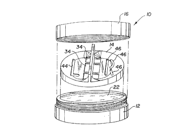
FIGURE 1 is an exploded view of a contact lens case
according to the present invention showing liquid
solution;
FIGURE 2 is a sectional elevational view thereof at
a smaller scale, showing contact lens in section and
liquid solution;
FIGURE 3 is a sectional view thereof taken at 3-3 of
Figure 2;
FIGURE 4 is a bottom view of a cap of a contact lens
case according to the present invention; and

v(~ ~~: ln~~ i 1>c'I/11~~J2/022.f1
il ~ :~ ~ a ;3
_4_
FICURE 5 is a sectional view thereof taken at 5-5 of
Figure 4.
Best Mode for Carryin4 Out the Invention
Referring now to the drawing, and in particular to
Figure 1, a contact lens case according to the present
invention is referred to generally by reference numeral
10. Case 10 includes a container 12) a tray 14 and a
removable cap 16. Referring also to Figure 2, container
12 includes both a bottom 18 and a~substantially upright
wall 20 for containing a quantity of liquid solution 22.
Tray 14 is designed to loosely fit within upright wall
for easy removal. Top surface 24 of tray 14 includes
a substantially flat circular inner portion 26 for
15 contact lens 28 to rest on and an annular beveled outer
portion 30 for retarding outward movement of contact
lens 28.
Referring now also to Figure 3, a divider such as a
dividing perpendicular bar 32 extends from top surface
20 24, separating the top of the tray into roughly equal
sections, each section slightly larger than one contact
lens 28. Tray 14 forms a plurality of apertures 34 from
top surface 24 through to bottom surface 36 on each side
of and adjacent to or in near proximity to dividing
perpendicular bar 32. Most of liquid solution 22 flows
through apertures 34 when tray 14 is lifted out of the
solution, pulling lens 28 toward the center of the tray
rather than washing or floating it over the side. Tray
12 also forms at least one aperture 44 from top to
bottom on one side of dividing perpendicular bar 32
forming the letter "L°' and at least one aperture ~46 from
top to bottom on the other side of the dividing
perpendicular bar forming the letter "R", The large

1vc ~ ~n % ~ c, i _ i I'('1'/11.~92/(12241
2i~83~~'~3
-5-
letters '°R" and "L" formed by apertures are easily seen
and can even be distinguished by feel in the dark.
Apertures 44 and 46 also help drain tray 12 as it is
lifted from the solution, but most of the drainage is
still from apertures 34 near the dividing bar.
Dividing perpendicular bar 32 also acts as a handle
for lifting the tray. The height of dividing bar 32,
being the distance from its base at top surface 14 to
the point on the bar which is the greatest perpendicular
distance away from the top surface, is less than one
third of its length or the diameter of the tray. This
allows the lens to only be a certain distance under the
fluid, reducing the chance of spilling from taking the
lens out of the solution and reducing the chance of
floating the lens off the tray. Because of the
semicircular shape of each tray half formed by dividing
bar 32, a user has easy access to opposite portions 38
and 40 of the lens edge when the lens is resting convex
side down on the tray top and the tray is removed from
the container.
Contact lens case 10 also includes a support member
42 for keeping bottom surface 36 of tray 14 from resting
on the bottom 18 of container 12. This allows the
keeping of the required amount of solution in the case
and essentially keeping lens 28 in the middle of the
solution. It also makes it easier to remove tray 14.
Referring now to Figure 4 and Figure 5) inside 48 of
remavable cap 16 forms ridges 50 to prevent the creation
of suction between the inside, of the cap and the concave
side of the lens should the case be turned upside down
or sideways during travel.
From the foregoing it will be seen that this
invention is one well adapted to attain all of the ends


~lc> o_''In1=.: 1'('I/lis~l2/(12241
~~~~~vJ
-6-
and objects hereinabove set forth) together with other
advantages which are inherent to the apparatus.
It will be understood that certain features and
subcombinations are of utility and may be employed
without reference to other features and subcombinations.
This is contemplated by and is within the scope of the
claims.
As rliany possible embodiments may be made of the
invention without departing from the scope thereof, it
is to be understood that all matter~herein set forth or
shown in the figures of the accompanying drawing is to
be interpreted as illustrative and not in a limiting
sense.

Representative Drawing
A single figure which represents the drawing illustrating the invention.
Administrative Status

For a clearer understanding of the status of the application/patent presented on this page, the site Disclaimer , as well as the definitions for Patent , Administrative Status , Maintenance Fee  and Payment History  should be consulted.

Administrative Status

Title Date
Forecasted Issue Date 1999-09-21
(86) PCT Filing Date 1992-03-18
(87) PCT Publication Date 1992-09-19
(85) National Entry 1992-11-17
Examination Requested 1996-05-14
(45) Issued 1999-09-21
Deemed Expired 2004-03-18

Abandonment History

There is no abandonment history.

Payment History

Fee Type Anniversary Year Due Date Amount Paid Paid Date
Application Fee $0.00 1992-11-17
Maintenance Fee - Application - New Act 2 1994-03-18 $50.00 1994-03-18
Maintenance Fee - Application - New Act 3 1995-03-20 $50.00 1995-03-16
Maintenance Fee - Application - New Act 4 1996-03-18 $50.00 1996-03-12
Registration of a document - section 124 $0.00 1996-05-30
Maintenance Fee - Application - New Act 5 1997-03-18 $75.00 1997-03-17
Maintenance Fee - Application - New Act 6 1998-03-18 $75.00 1998-03-11
Maintenance Fee - Application - New Act 7 1999-03-18 $75.00 1999-03-15
Final Fee $150.00 1999-06-15
Maintenance Fee - Patent - New Act 8 2000-03-20 $75.00 2000-02-16
Maintenance Fee - Patent - New Act 9 2001-03-19 $275.00 2002-03-18
Maintenance Fee - Patent - New Act 10 2002-03-18 $100.00 2002-03-18
Owners on Record

Note: Records showing the ownership history in alphabetical order.

Current Owners on Record
IVES IDEAS, INC.
Past Owners on Record
IVES, RAY C.
Past Owners that do not appear in the "Owners on Record" listing will appear in other documentation within the application.
Documents

To view selected files, please enter reCAPTCHA code :


To view images, click a link in the Document Description column. To download the documents, select one or more checkboxes in the first column and then click the "Download Selected in PDF format (Zip Archive)" or the "Download Selected as Single PDF" button.

List of published and non-published patent-specific documents on the CPD .

If you have any difficulty accessing content, you can call the Client Service Centre at 1-866-997-1936 or send them an e-mail at CIPO Client Service Centre.


Document
Description 
Date
(yyyy-mm-dd) 
Number of pages   Size of Image (KB) 
Claims 1998-09-30 8 351
Abstract 1994-02-27 1 19
Claims 1994-02-27 6 185
Drawings 1994-02-27 2 43
Description 1994-02-27 6 186
Representative Drawing 1999-09-13 1 11
Cover Page 1994-02-27 1 13
Cover Page 1999-09-13 1 54
Fees 2002-03-18 1 41
Correspondence 1999-06-15 1 29
International Preliminary Examination Report 1992-11-17 20 669
Prosecution Correspondence 1997-01-29 2 78
Examiner Requisition 1998-01-23 2 42
Prosecution Correspondence 1998-07-20 2 48
Examiner Requisition 1996-07-15 1 43
Prosecution Correspondence 1996-05-14 1 36
Office Letter 1993-06-02 1 52
Office Letter 1993-01-22 1 26
Fees 1997-03-17 1 41
Fees 1996-03-12 2 85
Fees 1995-03-16 1 55
Fees 1994-03-18 1 36