Note: Descriptions are shown in the official language in which they were submitted.
W092/00434 PCT/US91/02819
2~831~
METHOD FOR PLAZA DECK CONSTRUCTION
This invention relates to a method for
constructing plaza decks or the like. A plaza deck is
typically made up of a structural deck. a waterproof
(nonpermeable) membrane, an intervening foam insulation
board, and a top concrete wearing slab. A known problem
with this type of structure is a moisture build-up
between the wear slab and the membrane. This degrades
the insulation value of the foam insulation board and
can, and often does, cause freeze/thaw spalling of the
cementicious wearing slab. In order to alleviate the
problems caused by moisture build-up between the wearing
slab and the membrane, it is understood by the industry
(and further supported by ASTM standard) that drainage
is required (or at least recommended) between the
insulation and the top covering. Some applications also
include drainage between the membrane and the
insulation. Drainage reduces the possibilities of
moisture accumulation in the insulation (and therefore a
reduction in thermal resistance) and moisture
accumulation in the bottom side of the wear slab and,
therefore, reducing the potential for freeze/thaw
spalling.
W092/00434 PCT/US91/02819
-2-
2~8314~
With standard insulation products currently
being used in plaza deck construction. the drainage
layer usually consists of loose gravel or epoxy bound
gravel. This drainage layer is often covered with a
layer of construction fabric which is then covered with
poured concrete or a preformed concrete panel. The
labor and material costs associated with installation of
such a gravel layer above or above and below the
membrane are significant because loose gravel and/or
epoxy bound gravel require considerable handling
expertise in order for them to be transported to the job
site, and these materials ~equire intensive labor to be
applied. Further, the gravel layer adds weight
necessitating structural considerations and height which
is often limited in reroof situations causing detailing
difficulties.
Ways to avoid the installation of loose gravel
or epoxy bound gravel as the drainage layers in these
protected membrane roofing structures were recited in
U.S. Patents 4,658,554 and 4,712,349. In both of these
patents, the insulation layer itself provides the
necessary drainage in that the insulation is a type of
foamed plastic that is sculpted such that its top
surface is made up of elongated ribs arrayed, with cut-
out channels interposed between them, with the walls
surrounding the channels demarking the ribs. This
channel/rib construction provides for drainage of
moisture that accumulates between the insulation panels
and wearing slabs. In both of these patents all of the
insulation panels have a plastic film laminated to the
lower surface of the insulation panel such that the
plastic film prevents migration of moisture vapor
through the insulation to the insulation-wearing slab
3 20831~0 74641-5
lnterface from the waterproof membrane. This type of dual
molsture retarder and drain-away system provldes for
adequate drainage ln these types of rooflng structures.
The dlsadvantage of the methods outlined in the
'554 and the '349 patent is that ln both methods, ln order
to finlsh the roofing structure, concrete panels have to be
laid directly on top of the polystyrene foam. Because the
concrete panels have to be laid directly on top of the foam,
this means that these concrete panels have to be created in
one location, then transported to the ~ob site, and at the
~ob site the panels have to be llfted to the worklng area,
wherever lt may be--the roof--or varlous levels of a parking
structure. As is well known, the transportatlon of
extremely heavy, unbalanced concrete slabs ls dlfflcult,
tlme consumlng and extremely expenslve, both from a
materials standpoint and a labor standpoint. Further, a top
covering comprised of preformed wearing slabs is typically
not appropriate for loads heavler than pedestrian traffic.
For loads like vehicle traffic monolithic wearing slabs are
needed to adequately distribute loads and prevent damage to
the underlylng lnsulation layer.
According to the present invention there is
provlded a method for constructlng a plaza deck/parklng
structure according to the following steps
providing a plurality of panels of foam plastic
insulation having an alternately channeled and ribbed
surface structure;
~g
2083140
3a 74641-5
providlng a porous fabric layer sufficiently
porous to permit the passage of water vapor therethrough but
not so porous that wet concrete would signlflcantly
penetrate therethrough;
affixing the fabric layer to the top of said ribs
on each of sald panels;
provldlng a base deck;
placlng the plurallty of panels of foam plastic
insulation on top of a waterproof membrane; and
pouring wet concrete on top of the moisture
permeable fabric layer and allowing the concrete to cure to
a solid layer.
In the present invention, the need for gravel or
epoxy bound gravel layers and/or the need to use only
preformed concrete slabs is ellminated by replaclng standard
solld foam lnsulation or foam wlth top channels wlth a ~oam
lnsulation layer havlng dralnage channels formed ln lts
upper surface and also having a layer of porous construction
fabric stretched over said channels and afflxed to the foam.
Thls foam composlte is lald on the water lmpermeable layer,
fabrlc covered channels
"~
92/00434 PCTtUS9l/02819
-4-
= - 2083140
facing up, and wet concrete or an equivalent construc-
tion composite material is poured over said fabric.
After shaping to the desired size and thickness, the
concrete is allowed to cure in a conventional manner.
The resulting structure has excellent properties for its
intended use. This method also has a great cost savings
advantage over current typical methods of plaza deck
construction in that it is less labor intensive because
it eliminates certain layers of materials that have to
be applied. Also, it is less expensive because the
application of concrete is no longer a multi-step
process of forming the concrete, transporting it to the
job site, and applying it at the required level. With
this method the concrete is simply poured wet onto the
top of the foam layer and allowed to cure there, which
saves time, energy and money.
Fig. 1 is a fragmentary cross-sectional view of
a plaza or parking deck structure constructed in
accordance with the principles of the present invention;
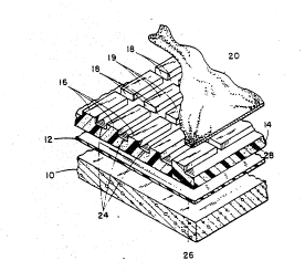
Fig. 2 is an exploded fragmentary perspective
view showing one embodiment of the cross-cutting
channels and rib structure in the foam panels and a cut-
away view of the porous fabric layer covering the panelwithout showing the top concrete layer; and
Fig. 3 is a fragmentary cross-sectional view of
another embodiment of the plaza or parking deck
structure, constructed in accordance with the principles
of the present invention, in which the foam layer
includes channels on both the top and bottom.
In the preferred embodiment. a waterproof
membrane 12 overlies a base deck 10 made of reinforc~d
''.
W O 92/00434 PC~r/US91/02819
~ 5
208314~
concrete or the like. Membrane 12 can be attached to
based deck 10, or can be placed loose on the deck.
Membrane 12 can be a single sheet of polymeric material,
liquid applied, modified bituminous sheet, or it can be
an asphalt built up membrane. Insulation foam panels
14, preferably made of polystyrene foam. are laid on top
of membrane 12. Foam panels 14 include, on the top
surface only, (Figs. 1 and 2) integral ribs 16
interspaced by channels or valleys 18.
The ratio of channel area to the total surface
area of the foam panel is 20 percent to 80 percent. A
ratio of 40 percent channel area to the total surface
area of the foam panel was selected as the ratio for use
in testing of the system. The channel area is defined
as the sum of the products of the widths and the lengths
of each of the bottoms of channels within the foam
panel. The total surface area of the foam panel is
defined as the area of the plane of the panel along the
surface defining the channeled and ribbed structure
therein. Alternately, the total surface area of a panel
may be defined as the sum of the channel area plus the
area of top surfaces 19 of ribs 16.
The channels either can be created when the
foam panel is extruded or they can be created by cutting
the panels after they have been formed. Methods found
to be workable in forming the grooves include cutting
them with a router or a hot wire or a hot knife.
There are no measurable differences in
compressive strength and moisture permeability of foam
panels that have had channels formed when the panels
W092/00434 PCT/US91/02819
2~3~4~
were extruded versus foam panels tha~ had had channels
cut into them by one of the above-listed methods.
The panels themselves have length and width
dimensions in which the length varies from 7.6
centimeters to 1.2 meters and the width varies from 1.2
meters to 6.1 meters. The dimensions of the panels
primarily used in the development of this invention were
0.6 meters by 1.2 meters and 0.6 meters by 2.4 meters.
Product size is not a critical factor, but handle-
ability is. Within these plaza deck construction areas,foam panels 14 must not be so large as to be blown from
a roof before concrete can be applied to hold them down.
The width of the channels in the top surface of
each panel varies from 0.16 centimeters to 2.5
centimeters. A midrange of values of the width of the
channels is 0.32 centimeters to 1.3 centimeters and the
width of the channels on the panels primarily used in
developing this invention was 0.48 centimeters to 0.95
centimeters.
The depth of the channels in the top surface of
each panel varies from 0.25 centimeters to 2.5
centimeters. A midrange of values for the depth of the
channels is 0.32 centimeters to 1.3 centimeters and the
depth of the channels on the panels primarily used in
creating this invention was 0.64 centimeters to 0.95
centimeters.
3o
The ribs around the channels in the preferred
embodiment varied in width from 0.32 centimeters to 12.7
centimeters. An intermediate range of values for the
width of the ribs is from 0.64 centimeters to 2.5
centimeters. The width of the ribs in the panels
W092/00434 PCT/US91/02819
2a8314(1
primarily used in creating this invention was 1.3
centimeters.
The compressive strength of the foam panels
varies from 69 kilopascals (kpa) to 1380 kpa. Target
values for compressive strength of the foam panels used
in developing this invention were 172 kpa, 345 kpa and
483 kpa. The compressive strength of the foam panels
would have to be greater when the depth of the channel
was reduced, in order for the channel to remain intact
0 because of the weight of the concrete.
The channel-rib structure on the foam panels
can be in any pattern desired from straight lines to an
interconnecting pattern of rectangular ribs and
channels, to some sort of diamond pattern or even a
"wiggle-waggle" pattern of interconnecting curved
channels with odd-shaped ribs. Fig. 2 shows a
rectangular pattern of inter-connected channels and ribs
on the top surface of the foam panel.
An additional pattern of channels and ribs can
be constructed on the bottom of each foam panel
(Fig. 3). Should there be this additional pattern of
channels and ribs on the bottom of each foam panel then
the ratio of channel area on the bottom to the total
channel area (on the top and bottom) is from 5 to 50
percent.
The foam material at the rib section 16 is
preferably stronger, more rigid, and more deformation
resistant than is the material 24 beneath channels 18.
In use, foam panels 14 are abutted together along the
longitudinal side edges 26 thereof. The ends 28 of
panels 14 also are abutted together. While these panels
W092/00434 PCT/US91/02819
2o83l~
are preferably made of polystyrene foam, other foam
insulating materials could also be used. The foam
panels made of polystyrene are made of the closed cell
variety of polystyrene to prevent moisture penetration.
Porous fabric 20 is adhered by an adhesive,
such as a hot melt adhesive or a 1-part or 2-part
urethane adhesive, to the top surface 19 of ribs 16, as
shown in Fig. 2. (The concrete wear slab 22 is not
shown in Fig. 2 so that fabric 20 is clearly visible.)
Fabric 20 may be affixed to foam panels 14 either prior
to or after the placement of panels 20 on membrane 12,
but is preferably affixed prior to such placement.
Fabric 20 is sufficiently porous to permit free passage
of water into the channels, but not so porous as to
permit wet concrete to significantly penetrate channels
18 on the top surface of panel 14. Porous fabric 20 can
be either a non-woven or woven fabric. Two materials
that fabric 20 could be made of include polypropylene
and fiberglass. Typical standards for the fabric are:
a weight per panel of 4.10 grams/square meter and grab
strength 52.2 kilograms; a flow rating of 42 liters per
square meter per minute; and an equivalent opening size
on U.S. units of 70 to 100. (These numbers are typical
property values and not to be construed as rigid
specifications.)
In use, impermeable membrane 12 is first placed
on base deck 10. Foam panels 14 are then arranged in a
3 closely adjacent edgewise fashion on impermeable
membrane 12, with the fabric covered channels facing up.
Once foam panels 14 are all in place, concrete is poured
on top of fabric 2C and allowed to cure into concrete
slab 22. During the pouring of the concrete, fabric 20
W092/00434 PCT/US91/02819
~ ~ 2~831~0
prevents the wet concrete from significantly entering
channels 18 in panel 14.
There is a slight adjustment in the level of
concrete required, for poured-in-place concrete top
coverings because the profiled surfaces reduce the
modulus of foundation at the foam. Therefore, when a
rib profiled product is considered, in order to maintain
the same maximum loading capabilities (flat board stock
and gravel versus profiled foam), a slightly thicker
concrete layer would be required (about 5 percent) if
the apparent foundation modulus of the insulation
product is reduced in half.
Fig. 3 illustrates an embodiment of the
invention in which channels are cut, not only in the
top, but also on the bottom of panel 14. Channel 17 on
the bottom of panel 14 can be aligned with channels 18
on the top of panel 14 in order to maximize the load
bearing strength of ribs 16. The embodiment shown in
Fig. 3, with a top and bottom pattern of channels would
have enhanced drainage capabilities.
This invention works to drain moisture away
from the critical layers in plaza deck construction
because the structure of the channels in the surface of
the foam insulation panels permits air circulation so
that any rain water or other moisture that penetrates to
the insulation layer is trapped and ends up dissipating
on hot, dry days. Moisture penetration of the foam
panel, and resulting loss of insulating qualities,
therefore, is substantially reduced by the present
invention. As stated in the previous section, certain
interconnecting patterns of channels allow for multi-
WOg2/00434 PCT/US91/02819
2~83 14~ -10-
directional drainage due to the cross-cutting linkage of
the ribs and channels.
An existing commercial product that will work
in the method of this invention to provide the fabric
covered insulation foam panels is STYROFOAM~ THERMADRY'~
Brand Insulating Drainage Panels of The Dow Chemical
Company. Styrofoam~ Thermadry~ Brand Insulating
Drainage Panels have heretofore been recommended for use
only in below-ground construction in which the panels
are placed vertically against an in-place foundation to
aid in drainage of moisture away from the foundation.
Styrofoam~ Thermadry~ Brand Insulating Drainage Panels
have not, prior to the present invention, been
recommended by the manufacturer for horizontal plaza
deck applications, where concrete would be poured over
the upper channeled surface.
These and other objects and benefits of the
invention will be more clearly understood with reference
to the attached drawings and appended claims. This
description of the preferred embodiment is not intended
to be a limitation on any obvious and expected
variations of the above-described invention.
3o