Note: Descriptions are shown in the official language in which they were submitted.
~.. 208332
A-8596
APPARATUS FOR MANUFACTURING PREFORMS FOR
BLOW MOLDING OF BELLOWS
Background of the Invention
The invention relates to an apparatus for manufacturing
tube - like preforms having a variable cross -section along
their length for blow - molding hollow bodies from a
thermoplastic material, which apparatus comprises a tubular
die and a collar die (injection molding die) having a
recess into which plastic material is injected, when the
collar die sits on the tubular die, the preform being
produced upon lifting of the collar die of the tubular die
and moving collar die to its predetermined position above
the tubular die. The apparatus further comprises a control
device for a drive displacing the collar die toward and away
from the tubular die, and a control device for a drive
responsible for changing the size of the exit opening of the
tubular die during movement of the collar die away from the
tubular die. The speed of the collar die increasesg from
zero up during away movement of the collar die. The control
devices are actuated upon start of lifting of the collar die
and effect a displacement dependent control.
An apparatus of this type is disclosed in German patent
.~. . ~UB~~~~
2
2,426,730. This apparatus functions according to a
PRESSBLOWER process. The control devices of this apparatus
are provided with switches which are actuated by the liftable
collar die. The preform produced in this apparatus have a
stepwise wall cross=section. The wall thickness of the
preforms in different regions has a different configuration.
and the change in cross-section of the preform is produced
in relatively little time. This known apparatus is poorly
adapted for producing preform for bellows. This apparatus
is not suited for producing preforms for bellows that should
have a substantially constant wall thickness despite having
numerous large pleats. This requires practically not
attainable large number of switches. It is also known, from
German patent 2,426,736, to control switches of the
control device of such an apparatus, which switches are
arranged along the displacement path of the collar die. by an
electronic prearranged program, If such a program is made
time - dependent, then frequent changes in wall thickness,
necessary for producing a preform for a bellows, cannot be
effected with a necessary precision, because conformity
between respective positions of the collar die cannot be
achieved with sufficient precision.
Accordingly, the main object of the invention is an
improved apparatus of the above - mentioned type which would
make it possible to produce preforms for bellow, that is
20833~~.
3 _
preform having a relatively high number of enlarged wall
thickness changes per unit of length, with an increased
precision.
Summary of the Invention
This and other objects of the invention are achieved by
providing an apparatus in which, according to the invention,
both control devices are associated with computer operable
during lifting of the collar die to produce a bellows, which
computer is provided with a program for producing a
required cross-section along the length of the
manufacturing preform in accordance with displacement of the
collar die during its lifting. According to the invention,
the collar die is connected with a continuously functioning
displacement measuring device that is connected, in turn,
with the computer. The increase in speed during lifting of
the collar die is controlled. Also during movement of the
collar die an oscillating larger and smaller controlled gap
cross-section is conformed to continuously controlled
speed ratio of the collar die, so that the thickness of the
wall of the produced perform is changed, in a wave - like
manner, from valleys to peaks.
The displacement of the collar die of the drawing
device is continuously measured and, dependent on
20~332~
respective positions of the collar die, two values, gap width
and drawing speed, are adjusted by the computer. The
displacement measuring devices according to the invention
permit to produces bellows or their preforms with an
increased precision, as a rule, from a thermoplastic
material. It is important to be able to change the gap
width frequently when the drawing speed is relatively
constant. The collar die is displaced with a speed that is
controlled from the very beginning. This permits immediate
conforming of the thickness of the preform to the collar die
displacement. The gap width change is programmed in
accordance with a speed ratio which remains constant during
displacement of the collar die along a programmed path. The
apparatus according to the invention operates in accordance
with PRESSBLOWER process.
The oscillation of the gap width is conformed to a
constant speed ratio, that is to a constant speed of the
reciprocating, in movable opposite direction, collar die. The
valleys and peaks of the wave - shaped (e. g., sinusoidal
wave) or arcuate thickness of the perform wall are defined,
dependent on the path of drawing, by the gap width. Because
the bellows cross - section of a to - be - produced bellows
is known, the wave form of the wall cross -section of the
perform can be defined. The profile precision of a bellows,
produces in an apparatus according to the invention, in the
CA 02083321 2001-08-08
longitudinal, direction and the circumferential precision
are improved because the perform is drawn strictly between
a centered tubular die and the collar die. In view of the
required increased precision, both drives in the apparatus
according to the invention, as a rule, are hydraulic drives
with control valves.
Thus, in one aspect, the invention provides an
apparatus for manufacturing a tube-like preform having a
longitudinal wall with a variable cross-section for flow
molding of a hollow body, such as a bellows, from a
thermoplastic material. The apparatus comprises a tubular
die having an exit opening with a variable cross-section,
and a collar die having a recess. The collar die is
movable into engagement with and away from the tubular die.
The thermoplastic material is injected through the exit
opening of the tubular die into the recess of the collar
die when the collar die sits on the tubular die. The
preform is manufactured upon movement of the collar die
away from the tubular die; first drive means for moving the
collar die into engagement with and away from the tubular
die; second drive means for varying the cross-section of
the exit opening of the tubular die; first control means
for controlling operation of the first drive means; and
second control means for controlling operation of the
second drive means. The first control means and the second
control means are actuatable during movement of the collar
die away from the tubular die, and are operable in
accordance with displacement paths of the collar die and
the second drive means.
Typically, the first control means and the second
control means are associated with computer means,
constantly operable during movement of the collar die away
from the tubular die, for producing the preform. The
CA 02083321 2001-08-08
5a
computer means is connected with storage means containing a
program for forming the variable cross-section of the wall
of the preform along its entire longitudinal extent in
accordance with a displacement path of the collar die when
it moves away from the tubular die. A speed of movement of
the collar die away from the tubular die, which increases
from a zero value, is continuously controlled, and
oscillations of larger and smaller cross-sections of the
exit opening of the tubular die are controlled in
accordance with a continuously controlled speed rate of the
movement of the collar die away from the tubular die.
Thus, the thickness of the wall of the produced preform
changes from peaks to valleys in a wave-like manner to form
the variable cross-section of the wall.
The invention relates not only to apparatus for
manufacturing preforms for hollow bodies by also to a
method of manufacturing same in a particular apparatus
operable in accordance with a predetermined computer
program. In this respect, the invention relates to a
method of producing a tubular preform having a variable
cross-section along its length for blow molding of bellows
from a thermoplastic material. According to the inventive
method, the plastic material is ejected into a recess of a
collar die sitting on a tubular die, and the preform is
produced upon lifting of the collar die of the tubular die.
The preform is formed in such a way that thickness of the
preform wall changes in a wave-like manner, with valleys
and peaks. The inventive method makes use of an apparatus
in which the control device for a drive for displacing the
collar die toward and away from the tubular die, and the
control device for a drive effecting the flow of plastic
material from the tubular die, are both operable during
lifting of the collar die of the tubular die. The drive
2083321
for effecting the flow of plastic material is operable to
change the width of the exit opening or gap of the tubular
die. During lifting of the collar die of the tubular die, the
speed of the collar die increases from zero on. During
further displacement of the collar die away form the tubular
die, the control devices are actuated and operate, dependent
on the collar die displacement. The collar die is connected
with a continuously operable displacement position measuring
device, which is connected to a computer operable during
lifting of the collar die and connected with both control
devices. To enable manufacturing of a preform having a
cross-sectional profile along its length corresponding to
that of a to-be-produced bellows-hollow body, the computer
is provided with a program based on the displacement path of
the collar die. The lifting speed of the collar die is
constantly controlled. During lifting of the collar die, the
oscillating larger or smaller gap width are controlled so s
to conform to the continuously controlled speed ratio of the
collar die.
Advantageously, the displacement measuring device
comprises an ultrasound position sensor including a position
indicating movable ring magnet in which a measuring tube
extends. The measuring tube encompasses a measuring wire
and is associated as with an electrical pulse sender so with
an ultrasound pulse receiver. This, per se known,
208332.
measuring device functions in contactless manner, is
wear-free. has a high resolution, and is not subjected to
soiling.
The bellows has five pleats, so that, correspondingly,
the oscillating larger and smaller gap width, upon lifting
of the collar die, form at least six elevations of wall
thickness and six indentations of the wall thickness.
The position measuring device and the computer enable a
very fine control. Advantageously, the oscillating larger
and smaller gap wiaths are controlled in accordance with a
straight bevel. Thinning and thickenning of the preform
cross-section corresponds to varying of the gap width along
he straight bevel. Thus, during manufacturing of the preform
not only arcuate waves are produced, but also thickness
increase or decrease is effected in accordance with
correspondingly short straight bevels. The axial length of
such a bevel should insure a predetermined distance between
pleat peaks and pleat valley of the bellows produced from the
preform .
The bellows produced from a preform, which is
manufactured according to the invention, can be used for
different applications. Use of the apparatus and method
according to the invention is especially advantageous for
producing axle cups for motor vehicles. The axle cups are
provided. e.g., for semiaxles of for drive axles. For this
.. . 208332
8
use, the advantage consists not only in that the bellows,
produced form a preform according to the invention, is made
of a thermoplastic material, but also in that the end pieces
are produced with high precision required by the axle cups.
The apparatus according to the invention enables to
effect a large number of wall thickness changes having
large radical dimensions with an increased precision. This
is achieved by providing in the tubular die an axially
displaceable die torpedo for changing the gap width and/or
when a plastic material is ejected from the tubular die by
using a pressure piston, movable along a straight line, an a
control device for controlling the pressure piston drive for
changing the pressure speed drive.
It is especially advantageous when the tubular die is
connected with a continuously operating displacement
measuring device Which is connected with the computer and
the die torpedo drive, and/or when the pressure piston is
connected with a displacement measuring device. which is
connected with a computer and operates in accordance with
pressure piston displacement. A respective displacement
measuring device comprises. preferably, an ultrasound
position sensor comprising a movable position indicator-ring
magnet which surrounds a measuring tube encompassing a
measuring wire and associated as with pulse sender so with
an ultrasound pulse receiver. All three position measuring
CA 02083321 2001-08-08
9
devices, used in the apparatus according to the invention,
measure the correcting variables of the apparatus,
necessary for appropriate shaping of a preform, with an
ultrasound position sensor. These measuring devices are
controlled by the computer, permitting achievement of an
increased precision in measurement.
Thus, in one aspect, the invention provides a method
of manufacturing a tube-like preform having a longitudinal
wall with a variable cross-section for blow molding of a
hollow body from a thermoplastic material. The method
comprises the steps of providing an apparatus including a
tubular die having a variable exit opening and a collar die
having a recess and movable into engagement with and away
from the tubular die; ejecting the thermoplastic material
through the exit opening into the recess of the collar die,
when the collar die sits on the tubular die, and producing
the preform by moving the collar die away from the tubular
die; forming a cross-sectional profile of the produceable
preform along its entire longitudinal extent in accordance
with the displacement path of the collar die when it moves
away from the tubular die; controlling increase of speed of
the collar die, as it moves away from the tubular die, from
zero on; and controlling varying of the cross-section of
the exit opening of the tubular die for providing
oscillating large and smaller cross-sections thereof
according to the continuously controlled speed ratio of the
collar die during movement of the collar die away from the
tubular die, whereby a thickness of a wall of the produced
preform changes from peaks to valleys in a wave-like
manner.
CA 02083321 2001-08-08
9a
Brief Description of the Drawings
The objects and features of the present invention and
the manner of attaining them will become more apparent and
the invention itself will by best understood from the
following detailed description of the preferred embodiment
read with reference to the accompanying drawings, wherein:
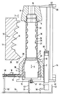
Fig. 1 shows a cross-sectional view of an apparatus
for manufacturing a preform for blow molding of a bellows;
Fig. 2 shows a diagrammatic view of a control device
for the apparatus shown in Fig. 1;
Fig. 3 shows a schematic view of a displacement
measuring device for the apparatus shown in Fig. 1, and
Fig. 4 shows a cross-sectional view of a bellows
to
208332.
produced by the apparatus shown in Fig. 1;
Detailed Description of the Preferred Embodiment
An apparatus for manufacturing preforms for blow
molding of bellows shown in Fig. 1 comprises a tubular die
30 which is shown in the lower portion of the drawing. The
tubular die 30 is formed of a die torpedo 1 and a die
land 2 that concentrically surrounds the die torpedo 1.
The die torpedo 1 and the die land 2 form together an upper
annular exit opening 3 through which plastic material is
delivered. While the die land 2 is stationary, the die
torpedo 1 is reciprocable in the directions indicated by
arrow 5. Opposite the tubular die 30, there is provided a
drawing device, also called a callar die 6, (injection die),
movable in the directions indicated by arrow 7. The collar
die 6 has a recess 9 facing downward and which passes into
the exit opening 3 when the collar die 6 sits on the
tubular die 30. The recess 30 encompasses an end portion
of a blow mandrel 10. Reference numeral 11 designates a
blow half-mold of a blow mold which closes or opens in
accordance with reciprocal movement of the half - molds
in the horizontal directions indicated by arrow 12. The blow
mold has an inner profile 13. The profile 13 corresponds
.a.. 208332.
11
to the outer profile of a bellows 8, shown in Fig. 4, when
the blow mold is closed.
When the collar die is lowered and sits on the tubular
die 30, and the blow needle engages the center region of the
die torpedo 1, a collar 17 of a plastic material is formed
in the recess 9. Upon movement of the collar die 6 upward
on injection of the plastic material through the exit opening
3, a preform 18 is formed. The start 19 of this preform 18
is formed. The start 19 of the preform-manufacturing is
produced when the collar die 6 sits on the tubular die 30.
The end 20 of this preform manufacturing is produced when
the collar die 6 is in its upper position shown in Fig. 1.
The die land 2 has, in its upper region. a bevel 22,
which is engageable by respective bearing surfaces 23 of the
blow half-molds 11 upon closing of the blow mold. The
bearing surface 23 is provided on a shoulder 25. The
shoulders 25 of the two blow half-molds 11 are displaced
toward the bevel 23 upon closing of the blow mold. Upon
closing of the blow mold, the preform is blown to its final
shape. Because the annular preform is formed as a
andulated piece, the plastic material extends uniformly
in the circumferential direction. Therefore, the waste is
smaller than with extrusion blow molding. The blow half -
molds are displaced on horizontal rails (not shown)
supported on a post. This post also supports the blow mold
w 208332
12
displacing devices each of which includes a double-acting
cylinder-piston arrangement acting on a respective blow half
-mold. The double - acting cylinder - piston arrangements
are connected by appropriate conduits with a source of a
pressure fluid. Fig. 1 shows a support 43 that supports a
drive 46 that acts on a projection 45 for displacing the
collar die 6. The drive 46 is likewise formed as a cylinder
-piston arrangement which is fed with pressure fluid through
a respective conduit 42.
The support 43 also supports a drive 47 which comprises
two cylinder-piston arrangements acting on the die torpedo 1.
These two cylinder-piston arrangements are likewise fed with
pressure fluid through respective conduits 42. There is
further provided a pressure piston 44 on which a drive 48
acts. The pressure piston 44 serves for delivering the
plastic material 4 in the direction toward the exit opening 3.
The conduits 42 discharge into control valves 50, 51 and 52,
which not only control the flow of pressure fluid to and
from respective cylinder-piston arrangements but also
control the amount of pressure fluid that passes
therethrough in a unit of time. The control valves 50. 51
and 52 communicate with a main conduit 54 connected to the
source of pressure fluid. The collar die 6, the die
torpedo 1, and the pressure piston 44 are associated,
respectively, with displacement measuring devices
M.. 208332
13
14, 15 and 16, which are shown in Fig. 1 only schematically.
The position measuring devices 14, 15 and 16 are connected
to a computer 21, The computer 21 is connected with a
storage 24 in which a program for manufacturing a bellows
or a corresponding to the bellow preform, is stored.
The computer 21 adjusts operation of valves 50, 51 and 52 in
accordance with the program and data received from the
displacement measuring devices 14, 15 and 16.
The three displacement measuring devices 14, 15 and 16
are shown with more details in Fig. 3. Each displacement
measuring device is formed as an ultrasound position sensor.
It includes a movable permanent ring magnet 26, connected
with a movable part whose displacement or position relative
to an initial or zero point is to be measured. The ring
magnet 26 includes a stationary ferromagnetic measuring tube
29. The measuring tube 29 is connected, at one end thereof,
to a sound absorber 31, and encompasses a measuring wire 32,
which is connected at an end thereof opposite to the one end
of the measuring tube 29, to an electrical pulse sender 33.
Electrical pulses are run along the wire 32 under action of a
circular magnetic field until the magnetic field strikes the
ring magnet 26 which, in response to being striked by the
magnetic field. generates a sound pulse which is absorbed by
the ultrasound pulse receiver 34. The time span between the
sending of the electrical pulse by the pulse sender 33 and
2fl~332~.
14
receiving the sound pulse by the pulse receiver 34 is a
measure of the position of the movable part of the ring
magnet 26.
The finished preform 18 has e.g " as shown in Fig, 1,
along its length six swellings 35 of the wall cross -
section, which extend from a section 36 through the peak 37
to a valley and give the cross - section altogether a wave -
like configuration. A bellows produced from the preform 18
has projecting pleats 38 separated by projecting inward
constriction 39. The bellows has two end portions 40 and
41, the inner dimensions of which are produced with a high
precision.
While a particular embodiment of the invention has been
shown and described, various modification thereof will be
apparent to those skilled in the art and, therefore, it is
not intended that the invention be limited to the
disclosed embodiment or to the details thereof, and
departures may be made therefrom within the spirit and scope
of the invention as defined in the claims.