Note: Descriptions are shown in the official language in which they were submitted.
~0~ 3~
SPECI~ICATIONS
A slalom gate is a vertical pole around which the skier must pass with his/her
skis in a predetermined direction. A winter slalom gate is planted into the
snow to such a depth as to withstand the impact of a skier. In addition, a
slalom gate has an articulation which enables the gate to fall when hit and to
recover to a vertical position immedia~ely after impact.
The Road Slalom Gate is designed to function exactly the same as a winter
slalom gate and is used by skateM wearing in-line skates. IJnlike the winter
slalom gates, the Road Slalom Gate rests on the su~face of the road. The road
surface is not penetrated or affected in any way.
A basic requirement in a slalom pole is that it must articulate at the grolmd
level, so that there will be no other resistance against the passing skater thanthe weight of the pole itself.
In all prior attempts, winter slalom poles have been used, with different base
types. However, due to the weight of the winter slalom poles all these
solutions have difficulties securing the base to the road surface. In one
example the base had to be weighted down with sand bags. In another
instance, the base was glued to the road surface. Such solutions are
impractical and make this type of training inaccessible to the majority of the
skaters.
The Road Slalom Gate sol~es these problems by using a lightweight pole made
of reinforced foam tube 125 cm high, attached to a flexible rubber base.
The rubber base rests freely on the surface of the road and provides stability
to the vertical pole through its weight and special shape. Due to its flexibility,
the mbber base will adjust to match the road surface variations.
In road t~als, I have found this solution to be very beneficiary to skiers, as
it eliminates the inhibition caused by the impact with a solid slalom pole.
UnlL~e the winter slalom gate, the 3~nad Slalom Gate does not require the use
of armour, other than the normal protection gear used by the in-line skaters.
The drawings which illustrate the Road Slalom Gate are:
- ~ig 1 elevation of the whole assembly. scale of 1:5
- Fig 2 plan of the whole assembly. scale of 1:5
- Fig 3 section through the articulation. scale of 1:1
- Fig 4 section through the articulation, with the pole leaning. scale of 1:1
- l~ig S elevation of the whole assembly, with the pole leaning. scale of 1:1
-: ::
. :' ` . :., ::' :`
::: , ` :. :. :
.;. :
~3~3~ 3
SPECI~CATIONS cont.
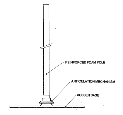
Figure 1 is a vertical elevation of the Road Slalom Gate assembly. The pole
is attached to the base through the articulation mechanism. When struck by a
passing skater, the pole moves away allowing unobstructed passage.
The Road Slalom Gate assembly consists of the rubber base, the lower
coupling piece, the articulation mechanism and the foam pole. The lower
coupling piece is attached to the rubSer base. The articulation mechanism is
attached to the pole. These two assemblies can be put togetlier or taken apart
through the lower and upper coupling pieces which are threaded. This design
also allows for compact storage and transportation.
~igure 2 is a horizontal plan of the pole and base assembly. This drawing
shows where the pole is placed on the base. The pole placement on the base
allows the same base to be used ~or left and right turning gates. The rubber
base geometry as shown in ~7ig 2, allows for maximum stability for the
weight.
~igure 3 is a section through ehe articulation mechar~ism. The articulation
mechanism is composed of the threaded upper coupling piece, the rubber
washer, the rubber disk, the pole holding cap, the elastic cord casing tube and
finally the elastic cord. The elastic cord is tensed and holds together all the
listed components. When tightened onto the lower coupling piece, the
articulation mechanism allows the pole to move in any direction, up to 90
degrees from the vertical.
Figure 4 is a vertical section through the articulation mechanism with the pole
pushed away from its vertical resting position. This section illustrates how thearticulation mechanism worl~s.
The articulation mechanism allows the pole to recover to vertical position
immediately after the impact. The rubber washer allows the pole to move and
recov~r with ease to and from small angles from the vertical, where the
momentum generated by the pole's own weight is small. Ihe larger rubber
disk generates enough momentum to raise the pole to vertical from any
position. This function is also aided by the rubber fioam disk which rests on
the base. When the pole falls, the rubber disk compresses the rubber foam
ring. All the energy generated by the falling pole is absorbed by the elastic
cord and the foam ring. This energy is used to lift the pole to the vertical
position.
Figure 3 also shows the foam tube composition. The major two properties of
this pole are its strength and light weight. The pole strength is obtained
through an outer layer ~vhich tightly covers the pole and thro~h an inner rigid
tube. The inner tube distributes the impact force over a larger area and in the
same time allows the pole to remain flexible. The inner tube also encases the
elaseic cord housing and the partial inner reinforcing rod.
;. ... ~ . . . . . .
- . . - .
- ~ ' , : . ' - :
~: . . ;:. . . . . . . . . .
,, :.. .. ..
