Language selection

Search

Patent 2083933 Summary

Third-party information liability

Some of the information on this Web page has been provided by external sources. The Government of Canada is not responsible for the accuracy, reliability or currency of the information supplied by external sources. Users wishing to rely upon this information should consult directly with the source of the information. Content provided by external sources is not subject to official languages, privacy and accessibility requirements.

Claims and Abstract availability

Any discrepancies in the text and image of the Claims and Abstract are due to differing posting times. Text of the Claims and Abstract are posted:

  • At the time the application is open to public inspection;
  • At the time of issue of the patent (grant).
(12) Patent: (11) CA 2083933
(54) English Title: GROUND-DRIVEN HYDRAULIC PUMP SYSTEM
(54) French Title: SYSTEME DE POMPAGE DU FLUIDE HYDRAULIQUE ENTRAINE PAR LA TRACTION AU SOL
Status: Deemed expired
Bibliographic Data
(51) International Patent Classification (IPC):
  • F04B 19/00 (2006.01)
  • B62D 5/32 (2006.01)
(72) Inventors :
  • BARBER, DENNIS RAY (United States of America)
  • SPARKS, GREGORY EVAN (United States of America)
(73) Owners :
  • DEERE & COMPANY (United States of America)
(71) Applicants :
(74) Agent: BORDEN LADNER GERVAIS LLP
(74) Associate agent:
(45) Issued: 1995-11-07
(22) Filed Date: 1992-11-26
(41) Open to Public Inspection: 1993-06-03
Examination requested: 1992-11-26
Availability of licence: N/A
(25) Language of filing: English

Patent Cooperation Treaty (PCT): No

(30) Application Priority Data:
Application No. Country/Territory Date
801,299 United States of America 1991-12-02

Abstracts

English Abstract


An engine-driven pump supplies pressurized hydraulic
fluid to vehicle brake and steering circuits. A ground driven
variable displacement pump controlled by a control circuit is
de-stroked when the engine-driven pump is operational. The
variable displacement pump includes a movable piston which
divides a bore into a pilot chamber and a pump chamber. An
outlet line with a check valve communicates fluid one way from
the pump chamber to the vehicle circuits. An inlet line with
a check valve communicates fluid one way from a reservoir to
the pump chamber. A ground-driven rotatable cam member
reciprocates the piston. A spring urges the piston towards
the cam member and towards a full stroke position. A pilot
line which communicates fluid pressure from an outlet of the
engine-driven pump to the pilot chamber. When the engine-
driven pump is operational the pressure in the pilot line
moves the piston away from the cam member, thus de-stroking
the variable displacement pump. When the engine-driven pump
stops, the pilot pressure drops, causing the variable
displacement pump to go into stroke. A relief valve may be
used to reduce the stroke of the variable displacement pump
when its output pressure is too high.


Claims

Note: Claims are shown in the official language in which they were submitted.


THE EMBODIMENTS OF THE INVENTION IN WHICH AN EXCLUSIVE
PROPERTY OR PRIVILEGE IS CLAIMED ARE DEFINED AS FOLLOWS:
1. In a vehicle having a hydraulic function, an engine-
driven pump for supplying pressurized hydraulic fluid to the
hydraulic function, a ground-driven source of pressurized
hydraulic fluid and control means for controlling operation of
the ground-driven source, the improvement wherein:
the ground-driven source comprises a variable
displacement pump, the variable displacement pump comprising a
variable stroke cylinder comprising a housing having a bore
therein, a piston movable in the bore and cooperating with a
wall of the bore to divide the bore into a pilot chamber and a
pump chamber, the piston being movable to a de-stroked
position in response to fluid pressure in the pilot chamber,
and resilient means biased to urge the piston to a stroked
position, and a rotatable member having a cam member
engageable with the piston to reciprocate the piston in
response to rotation of the rotatable member;
the control means comprises means for de-stroking the
variable displacement pump when the engine-driven pump is
operational, the control means comprising a pilot line for
communicating fluid pressure from an outlet of the engine-
driven pump to the pilot chamber, an outlet line for
communicating fluid from the pump chamber to the hydraulic
function, and an inlet line for communicating fluid from a
fluid reservoir to the pump chamber; and
a shuttle valve having an inlet shuttle port communicated
with the outlet of the engine-driven pump, a drain shuttle
port communicated with a fluid reservoir and a pilot shuttle
port communicated with the pilot chamber, a shuttle valve
member movable to a first position opening communication
between the inlet shuttle port and the pilot shuttle port and
blocking communication between the pilot shuttle port and the
drain shuttle port when the engine-driven pump is operational,
and a second position closing communication between the inlet
shuttle port and the pilot shuttle port and opening
communication between the pilot shuttle port and the drain
shuttle port when the engine-driven pump is not operating, and
a resilient member coupled to the shuttle valve member and


- 7 -

biased to urge the shuttle valve member to the second
position, the shuttle valve member being movable to the first
position in response to pressure in the inlet shuttle port.
2. The invention of claim 1, further comprising:
relief valve means for de-stroking the variable
displacement pump when output pressure from the variable
displacement pump exceeds a pressurized pressure.
3. The invention of claim 2, wherein the relief valve
means comprises:
an inlet relief port communicated with the outlet line of
the variable displacement pump, an outlet relief port
communicated with pilot chamber and a relief valve member
movable to a first position opening communication between the
inlet relief port and the outlet relief port when the output
pressure from the variable displacement pump exceeds a
predetermined pressure, and to a second position closing
communication between the inlet relief port and the outlet
relief port when the output pressure from the variable
displacement pump is less than a predetermined pressure, and a
resilient member coupled to the relief valve member and biased
to urge the relief valve member to the second position, the
relief valve member being movable to the first position in
response to pressure in the inlet relief port.
4. In a vehicle having a hydraulic function, an engine-
driven pump for supplying pressurized hydraulic fluid to the
hydraulic function, a ground-driven source of pressurized
hydraulic fluid and control means for controlling operation of
the ground-driven source, the improvement wherein:
the ground-driven source comprises a variable
displacement pump, the variable displacement pump comprising a
variable stroke cylinder comprising a housing having a bore
therein, a piston movable in the bore and cooperating with a
wall of the bore to divide the bore into a pilot chamber and a
pump chamber, the piston being movable to a de-stroked
position in response to fluid pressure in the pilot chamber,
and resilient means biased to urge the piston to a stroked
position, a rotatable member having a cam member engageable
with the piston to reciprocate the piston in response to
rotation of the rotatable member; and


- 8 -

the control means comprises means for de-stroking the
variable displacement pump when the engine-driven pump is
operational and relief valve means for de-stroking the
variable displacement pump when output pressure from the
variable displacement pump exceeds a predetermined pressure,
the control means comprising: a pilot line for communicating
fluid pressure from an outlet of the engine-driven pump to the
pilot chamber, an outlet line for communicating fluid from the
pump chamber to an outlet of the engine-driven pump, and an
inlet line for communicating fluid from an inlet of the
engine-driven pump to the pump chamber; and
the means for de-stroking comprising a shuttle valve
having an inlet shuttle port communicated with the outlet of
the engine-driven pump, a drain shuttle port communicated with
a fluid reservoir and a pilot shuttle port communicated with
the pilot chamber, a shuttle valve member movable to a first
position opening communication between the inlet shuttle port
and the pilot shuttle port and blocking communication between
the pilot shuttle port and the drain shuttle port when the
engine-driven pump is operational, and a second position
closing communication between the inlet shuttle port and the
pilot shuttle port and opening communication between the pilot
shuttle port and the drain shuttle port when the engine-driven
pump is not operating, and a resilient member coupled to the
shuttle valve member and biased to urge the shuttle valve
member to the second position, the shuttle valve member being
movable to the first position in response to pressure in the
inlet shuttle port.


-9-

Description

Note: Descriptions are shown in the official language in which they were submitted.


~ ~, 2083933
, ~ ,

AUXILIARY HYDRAULIC PUMP SYSTEM
Background of the Invention
Many vehicles have hydraulic brake and/or steering
systems which are powered by an engine-driven hydraulic pump.
Some such vehicles are so heavy that they cannot be manually
steered or braked in accordance with legal requirements in the
case of engine power failure. Therefore, an auxiliary source
of fluid pressure has been required in these cases to provide
hydraulic pressure to the steering and/or brake systems. This
need for an auxiliary source of fluid pressure has been
satisfied in the past by different means. For example,
accumulator systems are described in US Patent No. 4,326,558,
issued 27 April 1982 to Gage and US Patent No. 4,303,089,
issued 1 December 1981 to Gage et al. Systems with
electrically powered auxiliary pumps are described in US
Patent No. 3,820,620, issued 28 June 1974 to Miller et al. and
in US Patent No. 3,995,711, issued 7 December 1976 to Kittle
et al. Systems with ground-driven auxiliary pumps are
described in US Patent No. 4,160,490, issued 10 July 1979 to
Bexten et al., in US Patent No. 4,076,096, issued 28 February
1978 to Hushower et al. and in US Patent No. 4,015,681, issued
5 April 1977 to Shore et al. The typical ground-driven
auxiliary pump system includes a fixed displacement ground-
driven pump, a series of check valves to provide bi-
directional operation, and an unloading valve to reduce heat
generation when the engine-driven pump is operating.
Historically, accumulator and electric powered systems have
been preferred over ground-driven systems because
considerations of cost, complexity and power loss problems
associated with ground-driven systems have made them
impractical, even though performance and reliability may be
superior. It would be desirable to have a simple, low cost
and efficient ground-driven auxiliary pump system.
Summary of the Invention
An object of this invention to provide a low cost, simple
and efficient system which provides an auxiliary source of
pressurized hydraulic fluid for a vehicle hydraulic system.

~'

208~93~

Another object of this invention to provide such a system
which includes a ground-driven auxiliary pump.
Another object of this invention is to assure that the
variable displacement pump will be in full stroke when the
engine-driven pump is not operating.
Another object of this invention is to prevent pressure
loss from the pilot chamber to sump when pressure from the
engine-driven pump is high.
These and other objects are achieved by the present
invention which includes an engine driven main pump and an
auxiliary ground-driven variable displacement pump which
supply pressurized hydraulic fluid to vehicle brake and
steering circuits. A control circuit de-strokes the variable
displacement pump when the engine driven pump is operational.
The variable displacement pump includes a piston movable in a
bore in a housing. The piston divides the bore into a pilot
chamber and a pump chamber. An auxiliary outlet line with a
check valve communicates fluid one way from the pump chamber
to the vehicle circuits. An auxiliary inlet line with a check
valve communicates fluid one way from a reservoir to the pump
chamber. A ground-driven rotatable cam member engages the
piston to reciprocate the piston in response to rotation of
the rotatable member. A spring urges the piston towards the
rotatable member and towards a full stroke position. The
control circuit includes a pilot line which communicates fluid
pressure from an outlet of the engine-driven pump to the pilot
chamber. In addition, a relief valve may be used to reduce
the stroke of the variable displacement pump when the output
pressure of the variable displacement pump is too high. A
shuttle valve assures that the variable displacement pump will
be in full stroke when the engine-driven pump is not
operating, and prevents pressure loss from the pilot chamber
to sump when pressure from the engine-driven pump is high.
Brief Description of the Drawinqs
3S Fig. i is a partially cross sectional and partially
schematic view of one embodiment of the present invention;

2083933

Fig. 2 is a cross sectional view of the first embodiment
of the present invention.
Fig. 3 is a cross sectional and partially schematic view
of a second embodiment of the present invention.
Fig. 4 is a cross sectional view of the second embodiment
of the present invention.
Fig. 5 is a cross sectional view along lines 5-5 of Fig.
4.
Detailed Description
Referring to Figs. 1 and 2, a vehicle (not shown)
includes an engine 10 which, when operating, drives a
hydraulic pump 12 which draws hydraulic fluid from reservoir
14 through conduit 16 and supplies hydraulic fluid under
pressure through line or conduit 18 and check valve 19 to a
the vehicle hydraulic brake circuit 20 and, via a priority
valve 22, to the vehicle hydraulic steering circuit 24 and the
cooling and lube circuits 26. The check valve 19 permits flow
of hydraulic fluid from the engine-driven pump 12 to the brake
circuit 20 and the valve 22, while preventing such flow in the
opposite direction if the pressure on the engine-driven pump
side drops below a predetermined value. The priority valve 22
and the circuits 20, 24 and 26 are conventional and well-
known.
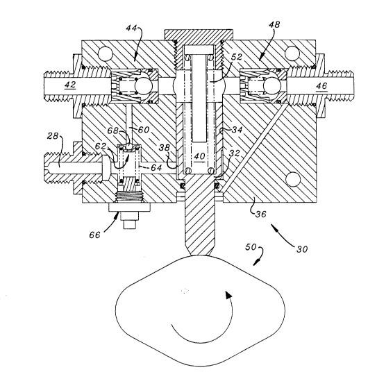
An auxiliary source of pressurized hydraulic fluid
includes a ground driven variable displacement pump 30 and a
control circuit for de-stroking the variable displacement pump
30 when the engine driven pump 12 is operational. The
variable displacement pump 30 includes a piston 32 movable in
a bore 34 in a housing 36. The piston 32 divides the bore 34
into a pilot chamber 38 and a pump chamber 40. An auxiliary
outlet line 42 with a check valve 44 communicates fluid one
way from the pump chamber 40 to the main outlet line 18. An
auxiliary inlet line 46 with a check valve 48 communicates
fluid one way from the main inlet line 16 to the pump chamber
40. A pilot line 28 communicates fluid pressure from the main
outlet line 18 to the pilot chamber 38.

2083933

A reversible ground-driven rotatable cam member 50
engages the piston 32 to reciprocate the piston in response to
rotation of the rotatable member 50. A spring 52 is mounted
in the pump chamber 40 and urges the piston 32 to a full
stroke position. When the pump 12 is operational the pressure
in the pilot line 28 moves the piston 32 away from the cam
member 50, thus de-stroking the variable displacement pump 30.
When the engine driven pump 12 stops operating or when the
engine 10 stops, the pressure in pilot line 28 drops, allowing
the piston to move towards the cam member 50, causing the
variable displacement pump 30 to go into stroke. Preferably,
in addition, a relief conduit 60 communicates outlet line 42
with pilot line 28. A relief valve 62 may be inserted in the
relief conduit 60 to reduce the stroke of the variable
displacement pump 30 when the output pressure of the variable
displacement pump 30 has reached the pressure which is
necessary for the brake and steering functions. Normally, a
spring 64 and tension adjusting device 66 biases a ball 68 of
the relief valve ~2 to a position is closing communication
from outlet 42 to pilot chamber 38.
When hydraulic pressure is present in conduit 18, as will
normally be the case when the engine 10 is operating, the
spring 52 will be compressed and the piston 32 will be shifted
to the left, viewing Fig. 1. When so shifted, the piston 32
will not reciprocate, or its stroke will be reduced as the cam
member 50 rotates.
If the engine 10 stops operating, then the main pump 12
will stop operating, and the hydraulic pressure in conduit 18
will be lost. The resulting drop in hydraulic pressure in
conduit 18 will be transmitted to the chamber 38 via pilot
line 28. When the pressure in chamber 38 drops to a certain
level, such as below 150 psi for example, the force of spring
52 will shift the piston 32 to the right and into engagement
with the ground driven cam member 50. In this position, the
stroke and the volume of fluid displaced from the piston 32 is
increased as the ground driven cam member 50 rotates.

2083~33

Thus, if the vehicle is traveling in a forward or reverse
direction, the brake and steering circuits 20,26 will receive
hydraulic fluid pressure from the auxiliary pump 30 to operate
the vehicle brake and steering systems as they normally would
in receiving hydraulic fluid from the engine-driven pump 12.
Referring now to Figs. 3, 4 and 5, the alternate
embodiment shown therein includes structure which is similar
to the embodiment of Figs. 1 and 2, and the same reference
numerals are use to indicate similar parts. Referring now to
Fig. 3, in this alternate embodiment a shuttle check valve 70
has a first or shuttle inlet port communicated with the outlet
of the engine driven pump 12, a second or drain port
communicated with the reservoir 14 and a third or shuttle
pilot port which is communicated with pilot chamber 38 via
passage 72, the bore of the relief valve 62 and passage 60.
Referring now to Figs. 4 and 5, the passage extending to
the left from relief valve 62 is blocked by a plug 74 and
passage 72 communicates passage 60 with a chamber 76 of
shuttle check valve 70. This chamber 76 is communicated with
reservoir 14 via valve seat 78 and passage 80 and with the
outlet of the engine driven pump 12 via valve seat 84 and
passage 82. A spring 86 normally biases the ball 88 of
shuttle check valve 70 into sealing engagement with valve seat
84. The ball 88 of shuttle check valve 70 moves into sealing
engagement with valve seat 78 and the shuttle check valve 70
blocks drain passage 80 when the outlet pressure from the
engine-driven pump 12 is high, as it is under normal
conditions, thus eliminating power loss through passage 80 and
orifice 81. When the pressure from the engine driven pump 12
is lost, then spring 86 will move the ball 88 away from seat
78 to open communication from chamber 38 to reservoir 14 via
passages 60, 72 and 80, thus placing the piston 32 in a full
stroke condition.
Also, as best seen in Fig. 4, a cap seal 90 (preferably
made of a low friction material) and an O-ring seal 92 are
installed in an annular seal groove 94 in the periphery of the
piston 32. The cap ~eal 90 and the O-ring seal 92 eliminate

2083933
drift and keep the piston 32 de-stroked when the engine driven
pump 12 is operating and the pilot pressure in chamber 38 is
high.
While the invention has been described in conjunction
S with specific embodiments, it is to be understood that many
alternatives, modifications and variations will be apparent to
those skilled in the art in light of the foregoing
description. Accordingly, this invention is intended to
embrace all such alternatives, modifications and variations
which fall within the spirit and scope of the appended claims.

Representative Drawing
A single figure which represents the drawing illustrating the invention.
Administrative Status

For a clearer understanding of the status of the application/patent presented on this page, the site Disclaimer , as well as the definitions for Patent , Administrative Status , Maintenance Fee  and Payment History  should be consulted.

Administrative Status

Title Date
Forecasted Issue Date 1995-11-07
(22) Filed 1992-11-26
Examination Requested 1992-11-26
(41) Open to Public Inspection 1993-06-03
(45) Issued 1995-11-07
Deemed Expired 1996-05-26

Abandonment History

There is no abandonment history.

Payment History

Fee Type Anniversary Year Due Date Amount Paid Paid Date
Application Fee $0.00 1992-11-26
Registration of a document - section 124 $0.00 1993-06-04
Maintenance Fee - Application - New Act 2 1994-11-28 $100.00 1994-11-25
Owners on Record

Note: Records showing the ownership history in alphabetical order.

Current Owners on Record
DEERE & COMPANY
Past Owners on Record
BARBER, DENNIS RAY
SPARKS, GREGORY EVAN
Past Owners that do not appear in the "Owners on Record" listing will appear in other documentation within the application.
Documents

To view selected files, please enter reCAPTCHA code :


To view images, click a link in the Document Description column. To download the documents, select one or more checkboxes in the first column and then click the "Download Selected in PDF format (Zip Archive)" or the "Download Selected as Single PDF" button.

List of published and non-published patent-specific documents on the CPD .

If you have any difficulty accessing content, you can call the Client Service Centre at 1-866-997-1936 or send them an e-mail at CIPO Client Service Centre.


Document
Description 
Date
(yyyy-mm-dd) 
Number of pages   Size of Image (KB) 
Cover Page 1995-11-07 1 16
Abstract 1995-11-07 1 34
Abstract 1995-11-07 1 35
Description 1995-11-07 6 274
Claims 1995-11-07 3 158
Drawings 1995-11-07 5 143
Representative Drawing 1999-06-18 1 32
Prosecution-Amendment 1994-06-24 1 32
Assignment 1991-10-22 14 413
Prosecution Correspondence 1993-06-03 2 38
PCT Correspondence 1995-08-30 1 32
Correspondence 1995-02-16 1 30
Fees 1995-02-03 1 46
Fees 1995-01-09 1 56
Fees 1994-11-25 2 117