Note: Descriptions are shown in the official language in which they were submitted.
~ 2~83992
FORCED CIRCUL~TION OVEN DOOR
Field of the Invention
This invention relates to cooking ovens and, more
particularly, to a door for a domestic cooking oven
having a forced air circulation system disposed within
the door for more rapidly and uniformly cooking food
products.
Backqround of the Invention
Ovens for domestic use today employ a wide variety
of cooking methods. The most common types of ovens are
the conventional electric and gas ovens which cook the
food by radiant heat.
In cooking with an oven, a principal objective is
frequently (for example, when baking) to achieve a
substantially uniform temperature throughout the
interior of the oven chamber as the quality and
"doneness" of the cooked food product is closely related
to the uniformity of interior oven temperature. A
problem with conventional ovens is often the non-
uniformity of the temperature within the oven chamber.
Conventional ovens typically have a natural hot air flow
pattern dictated by the interior geometry of the oven
that results in uneven heating within the oven chamber
and food that is not cooked uniformly. Thus, it is
important to achieve substantially uniform heating of
the oven cooking chamber.
Convection ovens employ a blower means in the oven
chamber to circulate air at elevated velocities within
the oven chamber to improve heat distribution and the
effectiveness of the heating elements and to reduce the
cooking time. In many cooking situations, there is
often a layer of air adjacent the surface of the food
being cooked and/or the cooking utensils which provides,
__ ~
20~39g2
in effect, a thermal barrier that retards the cooking
process. The increased circulation of heated air that
may result from forced air flow may eliminate this
barrier, thereby facilitating the transfer of heat to
the food and resulting in faster cooking times. In
addition, the circulation of heated air within the oven
chamber generally improves the temperature uniformity
within the oven and contributes to more even cooking.
Prior attempts at providing an effective convection
oven are numerous. U.S. Pat. No. Re. 26,063 (originally
U.S. Pat. No. 3,074,393) discloses an oven provided with
a blower-and-motor assembly mounted ad~acent the rear
wall in the interior of the oven chamber. A baffle
plate positioned in front of the blower is formed with
a central aperture which permits air to flow axially
into the blower impeller which, in turn, expels the air
radially outwardly, in a turbulent manner, toward the
sides, top and bottom walls of the oven chamber as
directed by the baffle plate.
U.S. Pat. No. 4,010,341 discloses a well-type oven
equipped with a fan, a heater and a plurality of
circulation passages. The oven of the '341 patent
comprises a well which is positionable within a counter
or similar support, is open at the top, and has a
removable insert disposed therein defining, together
with the well, the circulation passages. The fan and
the heater are positioned in the lower side of a lid
that is removably fitted over the well to define a top
closure for the oven.
U.S. Pat. No. 4,687,908 discloses a portable, self-
contained convection blower for use with conventional
ovens. The portable electric blower may be placed on
the floor of the oven to circulate heated air throughout
the oven chamber.
U.S. Pat. No. 4,484,063 describes a convection oven
having an air-distribution chamber disposed above the
main cooking compartment. The oven of the '063 patent
2~83~9
.
includes a centrifugal fan disposed behind a diffuser
panel which is provided with discharge openings of non-
uniform size and asymmetrical patterns. The discharge
openings are so arranged to take advantage of the oven
geometry in an attempt to achieve uniform heating of the
cooking compartment with a closed-air circulation
system.
U.S. Pat. No. 4,813,398 discloses a gas-fired
convection oven comprising a blower fan mounted on the
rear wall of the interior of the cooking chamber. A
vertical shroud is mounted adjacent the fan opposite of
the rear wall to form a narrow heat-exchanging chamber
within the oven chamber. The vertical shroud is formed
with a partially baffled, centrally disposed air opening
lS to ensure that each of the two legs of a heat exchanger
receive approximately equal portions of combustion air
and gas such that uniform heating of the heat exchanger
is possible in an attempt to achieve better heat
distribution throughout the interior of the cooking
chamber.
U.S. Pat. No. 4,829,158 discloses a portable
electric convection oven having a blower means provided
in a side wall of the oven housing. The interior of the
oven is organized with a central food receiving area
spaced between upper and lower air-distribution plenums.
Separating the plenums and the central food receiving
area are two removable air-distribution plates that are
provided with formed perforations therein that define
nozzles to direct the heated air against the food
products.
Attempts have also been made to position a fan
means within the door of a dishwasher for circulating
air within the washing chamber during the drying cycle.
Exemplary of such attempts are U.S. Pat. Nos. 3,068,877
and 3,908,681.
U.S. Pat. No. 3,068,877 describes a dishwasher door
having a first conduit located within the door in
2083~92
communication with the dishwasher chamber and a second
conduit in communication with the atmosphere and in heat
exchange relationship with the first conduit. The door
of the '877 dishwasher further includes a blower system
driving a first impeller disposed in the first conduit
for recirculating vapor from the dishwashing chamber and
a second impeller disposed in the second conduit for
circulating cooling air from the atmosphere.
U.S. Pat. No. 3,908,681 describes a forced-air
circulation system for a dishwasher, incorporating a
fan-and-motor assembly mounted within the dishwasher
door for circulating air downwardly through the wash
chamber during the drying cycle.
As noted above, forced convection ovens generally
offer an advantage over conventional ovens in their
reduction of cooking times by more uniform heat transfer
to the food product. With prior ovens, forced
circulation systems were formed in the walls of the oven
chambers where the blower and motor were relatively
inaccessible and their location exposed them to the high
temperatures of the oven chamber and required relatively
expensive motors and insulating structures designed for
high temperature operation. Furthermore, location of
the forced circulation system within the oven reduced
the interior capacity of the oven chamber.
summarY of the Invention
This invention comprises a door for a forced
convection electric or gas oven that provides forced
circulation of the heated air within the interior of the
oven chamber. The oven door of this invention generally
comprises an outside door wall, an inside door wall, a
plurality of interior walls disposed between the outside
door wall and the inside door wall that form an air-
directing plenum carried within the oven door. The
inside door wall has a plurality of openings between the
air-directing plenum and the interior of the oven
2~3992
.
chamber, and a motorized fan assembly located within the
door circulates air through the plurality of openings in
the inside door wall, the air-directing plenum and
throughout the interior of the oven chamber.
The oven door provided by this invention includes
a window for providing visual access to the interior of
the oven, and the interior walls of the oven door
preferably form a U-shaped air-directing plenum with a
central portion below the window and a pair of outer
portions extending along the outer edges of the inside
door wall on both sides of the window.
The plurality of openings provided in the inside
door wall of the oven door are preferably located in a
plurality of groups of openings. A first group of
openings is located to communicate with the central
portion of the air-directing plenum and the central
portion of the oven chamber. A second group of openings
is preferably located in each of the outer portions of
the air-directing plenum to communicate with the outer
portions of the oven chamber. The inside door wall can
further carry a removable cover for the air-directing
plenum having the plurality of openings formed therein
and further carrying a plurality of air-directing vanes
positioned adjacent to the second group of openings
formed in the outer portions of the air-directing
plenum.
The fan assembly provided by this invention is
preferably located adjacent to the first group of
openings and is adapted to draw air from the central
portion of the oven chamber interior into the air-
directing plenum through the first group of openings and
expel air into the outer portions of the oven chamber
interior through the second group of openings located in
the outer portions of the air-directing plenum.
A first interior wall of the plurality of interior
walls of the oven door is preferably disposed between
the fan and the fan motor to define the air-directing
2~839~2
plenum on the inward or oven side of the first interior
wall and a chamber on the outward or room side of the
first interior wall. The motor carries an additional
fan disposed within the chamber for circulating air
within the chamber to cool the motor during operation.
A second interior wall of the plurality of interior
walls can be positioned to provide thermal insulation
between the air-directing plenum and the outside door
wall of the oven door.
The positioning of the forced circulation system
and motorized fan assembly within the oven door does not
interfere with oven chamber size and provides a modular
design. Oven chambers can be designed and built to
provide both conventional and forced circulation
systems, and oven doors provided by this invention can
be added or affixed to the oven after the construction
of the oven unit is completed. The space adjacent the
rear wall of the oven chamber, which has traditionally
been reserved for the convection motor assembly in prior
systems, is available under the present invention for
other features, including rear venting or deeper oven
capacity.
The foregoing and other features of the invention
will be more particularly described in connection with
the preferred embodiment of the invention and with
reference to the accompanying drawings.
Brief Descri~tion of the Drawinqs
Fig. 1 is a perspective view of an oven having a
forced circulation system provided by this invention,
the top and side walls of the oven being partially
broken away for purposes of illustrating the interior of
the oven door of this invention;
Fig. 2 is a side cross-section of an oven having
the forced circulation system of Fig. 1;
Fig. 3 is an exploded perspective view of the oven
door assembly of Fig. 1; and
--6--
20~3992 ~ ~
~ J
Fig. 4 is an enlarged cross-section through the
oven door provided by this invention to more clearly
show its interior arrangement.
Description of the Preferred Embodiment
This invention relates to an oven door including a
forced-air circulation system for more rapidly and
uniformly cooking food products in an oven.
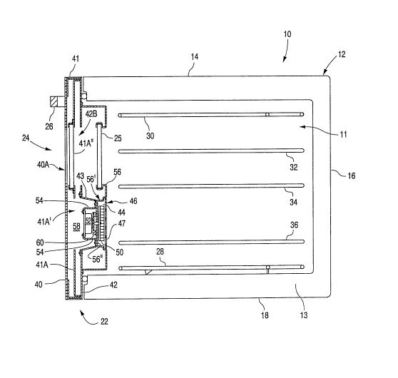
As shown in Figs. 1 and 2, oven 10 preferably
comprises a box-like structure 12 having a top wall 14,
a rear wall 16, opposing side walls 20 (for purposes of
illustration, the foreground side wall in Fig. 1 has
been omitted) and a front wall 22, all of which
collectively form an interior heating or cooking chamber
11. Front wall 22 is formed by a hinged oven door 24
adapted to be opened by a handle 26 to provide access to
the interior heating chamber 11. Oven 10 can further
include one or more heating elements (not shown in Fig.
1) operatively supported within the heating chamber 11
for heating and cooking food products. Where the oven
is an electric oven, such heating elements can include,
as shown for example in Fig. 2, a baking heating element
28 located adjacent to the bottom wall 18 and a broiling
heating element 30 located adjacent to the top wall 14.
While not shown, it is understood that oven 10 can be
connected to an energy source, such as a source of
electrical energy, which can provide energy to the
heating elements such as elements 28, 30. In a gas oven
of the invention, gas burners within the oven chamber
will be connected with a source of gas. The walls of
the heating chamber 11 can also support a plurality of
racks for supporting the food products received within
the oven, including an upper rack 32, a middle rack 34
and a lower rack 36. The walls forming the box-like
structure 12 can have interior spaces 13 with insulation
to retain the high temperatures within the heating
~0839~2
chamber 11 and to reduce the temperatures of the outer
walls at the exterior of oven 10.
Oven door 24, shown in an exploded perspective view
in Fig. 3 and in a cross-section view in Figs. 2 and 4,
preferably comprises an outside door wall 40 and an
inside door wall 42 and a plurality of interior door
walls forming an air-directing plenum 44 inside of door
24 as set forth further below. Inside door wall 42
carries a tub-like door plug member 56, preferably
constructed of porcelain-coated steel, having an opening
56A in its upper central region. Door plug member 56 is
drawn inwardly in its lower portion to form a recession
56' (when viewed from cover plate 46 of Fig. 3).
Recession 56' is located below the opening 56A and
extends in a U-shape upwardly at each side of the
opening 56A. Cover plate 46 is positioned to cover the
recession 56' on the inward or oven side of door plug
member 56 and, in cooperation with door plug member 56,
defines an air-directing plenum 44 therebetween, as
shown in Figs. 2 and 4. Cover plate 46 is formed with
a plurality of openings 47, 48 formed therein for
allowing air circulation between the air-directing
plenum 44 and heating chamber 11. An impeller or fan 50
is located in the air-directing plenum 44 to be driven
by a motor 52, supported by a pair of Z-brackets 54
outside of the air-directing plenum 44. Motor 52 is
coupled with the electrical energy source located
outside of the oven door 24 which operates the oven 10.
Upon operation of motor 52, air is circulated through
the plurality of openings 47, 48 provided in cover plate
46 between the air-directing plenum 44 within door 24
and the interior of the heating chamber 11 of oven 10 as
indicated in ~ig. 1.
As best shown in Figs. l and 3, the plurality of
interior door walls provided by this invention form a U-
shaped air-directing plenum 44 formed by recession 56'
with a central portion below the opening 56A and outer
2083992
leg portions extending upwardly along the outer edges of
the door plug member 56 on both sides of the opening
56A. While not individually numbered in the drawings,
the central and outer leg portions of the recession 56'
forming air-directing plenum 44 generally correspond
with the central portion 46A and outer leg portions 46B
of cover plate 46 shown in Fig. 3. The plurality of
openings provided in the cover plate 46 are arranged,
preferably, in a first group of openings 47 located in
the central portion 46A of cover plate 46 to provide air
communication between the central region of the heating
chamber 11 and the central portion of air-directing
plenum 44, and a second group of openings 48 located in
each of the outer leg portions 46B of cover plate 46 to
provide air communication between the outer portions of
the heating chamber 11 and the outer leg portions of
air-directing plenum 44. Fan 50 can be located adjacent
to the first group of openings 47 to draw air through
the first group of openings 47 from the central region
of the interior of heating chamber 11 into the air-
directing plenum 44, as shown by larger single reference
arrow "a" in Fig. 1, and to expel air into the outer
portions of the interior of heating chamber 11 through
the second group of openings 48, as shown by smaller
multiple reference arrows "b" in Fig. 1. Air-directing
vanes 61, 62 can be disposed within plenum 44 adjacent
to the second group of openings 48 for directing the air
within the air-directing plenum 44 to provide desirable
distribution within the heating chamber 11 from the
second group of openings 48. While the drawings depict
the openings 47 of the first group to be circular and
the second group of openings 48 at each leg portion 46B
as comprising a vertical column of horizontal ovals
positioned above a circular orifice, the specific size,
number and spacing of the openings of either or both
groups can be varied.
-
2~8~992
.
A first interior wall, defined by door plug member
56, defines an interior partition means 56'' at the
bottom of recession 56' which lies between the fan 50
and the motor 52, as shown in Figs. 2 and 4, and forms
an interior chamber 58 between the outside door wall 40
and door plug member 56. Motor 52 is located within
chamber 58 and its drive shaft 53 extends through a
central aperture 56B provided in the interior partition
means 56'' at the bottom of recession 56' of door plug
member 56 and carries fan 50 at its distal end.
Preferably, motor 52 also drives a second impeller or
fan 60 secured to drive shaft 53 and located within
chamber 58 on the outer side of interior partition means
56'' of door plug member 56 for circulating air within
chamber 58 to provide cooling for the motor 52 during
operation. As shown in Fig. 4, a second interior wall
defined by a baffle member 41A can be positioned between
the inside door wall 42 and the outside door wall 40 of
the oven door 24 to provide thermal isolation.
One preferred structure of oven door 24 will now be
described in further detail with reference to Fig. 3,
which presents an exploded perspective view of one oven
door 24 and forced circulation system provided by this
invention. Outside door wall 40 is supported on a frame
member 41, which may be a painted steel frame, providing
an outer wall assembly. outside door wall 40 may be
constructed of steel, plastic, glass, or the like, and
is preferably constructed of darkened, heat-resistant
glass, such as PYREX, with a clear portion 40A provided
therein for visibility. outside door wall 40 may be
affixed to frame member 41 through conventional means,
including adhesives, welding or mechanical fasteners,
such as screws or nuts and bolts, for example. Attached
to the outward side of wall 40 adjacent its top is a
handle 26 which may be used to open oven door 24 to
provide access to the interior heating chamber 11.
--10--
2~83g~2
.
An inner door assembly is provided by inside door
wall 42, preferably defined by a door liner constructed
of porcelain-coated steel having a first opening 42A in
its lower central region and a second opening 42B in its
upper central region. Inside door wall 42 carries door
plug member 56. A truncated-pyramidal "scoop" member 43
is positioned within opening 42A and fastened to inside
door wall 42 by conventional means. Baffle member 41A,
which is preferably constructed of steel and includes an
opening 41A' in its lower central region and carries a
thermal window 41A'' in its upper central region, fits
within inside door wall 42 which, in turn, fits within
frame member 41. Opening 42A communicates with opening
41A' provided in baffle member 41A. The mounting
assembly for motor 52, defined by Z-brackets 54, is
conventionally affixed to the outward side of recession
56' of door plug member 56 at mounting holes
corresponding with mounting holes provided in the Z-
brackets 54 so that the drive shaft 53 of motor 52
extends through central aperture 56B as best shown in
Fig. 4. A window Z5 is secured within opening 56A in
door plug member 56. (A visual access path is thereby
defined by clear portion 40A of outside door wall 40,
thermal window 41A'' of baffle member 41A, opening 42B
of inside door wall 42 and window 25.) The door plug
member 56 is secured to the inward side of the door
liner 42 so that the motor 52 and its mounting Z-
brackets 54 are received through and fit within the
opening 43A provided in scoop 43. The inward edge of
scoop 43 rests adjacent to the outward side of the
recession 56' of door plug member 56 (best seen in Fig.
4) and thereby cooperates to define interior cooling
chamber 58. Door plug member 56 may be secured to door
liner 42 along its perimeter flange 57. Cover plate 46
is removably fastened, for example, by machine screws,
to the inward side of door plug member 56 over the
2083992
recession 56' to define therebetween the air-directing
plenum 44.
As noted above, the oven door 24 of this invention
draws air through the first group of openings 47
provided in the central portion 46A of cover 46 into
air-directing plenum 44 and expels air out into the
heating chamber 11 through the second group of openings
48 provided in the outer leg portions 46B of cover plate
46. Thus, this invention provides an oven door
providing forced circulation of the air within an oven
interior comprising an outside door wall and an inside
door wall forming a door for the oven, and a plurality
of interior door walls disposed therebetween to form an
air-directing plenum within the oven door, and a
motorized fan assembly located within the oven door so
that operation of the motor forcibly circulates air
through a plurality of openings provided in the inside
door wall, the air-directing plenum and the interior of
the oven heating chamber.
The oven door system that has been described above
is a preferred embodiment provided by this invention and
modifications and variations may be made to this
embodiment without departing from the scope of the
invention as defined in the following claims and the
prior art and such modifications and variations are
considered to be within the purview and scope of the
claims.
-12-
-