Language selection

Search

Patent 2084026 Summary

Third-party information liability

Some of the information on this Web page has been provided by external sources. The Government of Canada is not responsible for the accuracy, reliability or currency of the information supplied by external sources. Users wishing to rely upon this information should consult directly with the source of the information. Content provided by external sources is not subject to official languages, privacy and accessibility requirements.

Claims and Abstract availability

Any discrepancies in the text and image of the Claims and Abstract are due to differing posting times. Text of the Claims and Abstract are posted:

  • At the time the application is open to public inspection;
  • At the time of issue of the patent (grant).
(12) Patent Application: (11) CA 2084026
(54) English Title: ILLUMINATION OF DISPLAYS
(54) French Title: ECLAIRAGE POUR AFFICHAGE ELECTRONIQUE
Status: Dead
Bibliographic Data
(51) International Patent Classification (IPC):
  • G09G 3/36 (2006.01)
  • G09G 3/34 (2006.01)
(72) Inventors :
  • BEESLEY, GRAHAM EDGAR (United Kingdom)
(73) Owners :
  • AT&T WIRELESS COMMUNICATIONS PRODUCTS LTD. (United Kingdom)
(71) Applicants :
(74) Agent: FETHERSTONHAUGH & CO.
(74) Associate agent:
(45) Issued:
(22) Filed Date: 1992-11-27
(41) Open to Public Inspection: 1993-05-29
Examination requested: 1994-09-01
Availability of licence: N/A
(25) Language of filing: English

Patent Cooperation Treaty (PCT): No

(30) Application Priority Data:
Application No. Country/Territory Date
9125331.0 United Kingdom 1991-11-28

Abstracts

English Abstract


ABSTRACT

A problem arises in electronic equipment
incorporating a display, such as an LCD display, which
is not intrinsically illuminated. The present
invention provides a controlled backlight for such
displays, and is particularly useful in battery-
powered equipment where power consumption must be kept
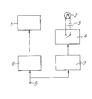
to a minimum. The circuitry comprises a display 1
controlled via a conventional display driver 6 from
other equipment (not shown) such as a microprocessor.
Whenever the display is changed a signal is sent also
to a timer circuit 7 which triggers, and passes a
control signal to an electronic switch 4 which in turn
passes power from a battery 3 to a lamp 2. The lamp
2 is arranged to illuminate the display 1. After a
preset period, the timer circuit 7 sends a further
control signal to the switch 4 to switch lamp 2 off.


Figure 1.


Claims

Note: Claims are shown in the official language in which they were submitted.


-6-

CLAIMS

1. Electronic equipment including a display and
characterised by means for illuminating said display,
and means controlling said illuminating means for
switching on the illumination only as a result of the
occurrence of a change in the display.
2. Electronic equipment as claimed in claim 1
wherein the display is not intrinsically illuminated.
3. Electronic equipment as claimed in claim 2
wherein the display is an LCD display.
4. Electronic equipment as claimed in any one of
claims 1 to 3 wherein said controlling means comprises
means for detecting the occurrence of a display
change, and outputting a control signal as a result of
such change, and switch means, controlled by said
control signal, for switching said illuminating means
on.
5. Electronic equipment as claimed in claim 4
wherein said detecting means forms part of a
microprocessor which also controls the display itself.
6. Electronic equipment as claimed in any one of
the preceding claims further comprising a timer for
controlling the time for which said illuminating means
is switched on.
7. Electronic equipment as claimed in either one
of claims 4 or 5, and claim 6 wherein said timer is
controlled so as to commence timing upon switching on
of the illuminating means, and to output a further
control signal to said switch means after a preset
period to switch said illuminating means off.
8. Electronic equipment as claimed in claim 7
wherein said timer forms part of said microprocessor.
9. Electronic equipment as claimed in any one of
the preceding claims, which is battery powered.


Description

Note: Descriptions are shown in the official language in which they were submitted.


2 ~i

"IhLUMINATION OF DISPLAYS"

This invention relates to illumination of
displays, and is particularly directed to illumination
of displays which are not intr:Lnsically illuminated,
such as LCD displays.
Displays are, by and large, meant to be
readily seen and understood by a user. Many displays
are intrinsically illuminated and do not usually need
further illumination. However, some displays, the
most obvious example beiny LCD displays, are not in
themselves illuminated and, in the absence of a
reasonably strong ambient light, need a background
illumination if they are to be easily seen by a user.
This invention concerns an improved means of providing
such illumination, as well as providing additional
illumination to displays whose inherent illumination
is not sufficient to be easily seen.
A common means of providing such illumination
is by way of a separate light, for example a
backlight, which is switched on or off according to
need. Where power consumption is not a problem such
lighting may be permanently switched on; where power
needs to be conserved, for example in battery-operated
equipment, switch means may be provided to enable the
user to manually switch on the light when needed
either momentarily, or for a fixed duration.
In the present invention, a further
improvement in battery consumption is achieved by
providing means for enabling the light only as a
result of a change of display. Preferably, once
enabled, the light will remain enabled for a pre-
determined duration. It will be noted that the
control of the light is independent of the source or
cause of the display change - i.e. whether as a result
of user actions or otherwise.

o ,~ ~3

-- 2

The invention finds particular application in
cases where the power consumption is critical - for
e~ample portable equipment - and which may receive
display changing information, such as messages,
without any user interaction. User actions will also
in general enable the display light via the same
mechanism by virtue of the upclating of the display
caused by the users input.
In order that the inverltion may be better
understood, an embodiment thereof will now be
described by way of example on].y, and with reference
to the accompanying drawings irl which:
Fiyure 1 is a block diagram of a display unit
incorporating an illuminating light according to the
invention;
Figure 2 is a view similar to Figure 1, but
showing the particular application of the invention to
a cordless telephone; and
Figure 3 is a diagram of the controlling logic
within the rnicroprocessor ~orming part of the cordless
telephone of Figure 2.
Referring to Figure 1, the display to be
illuminated is represented by the reference 1. This
will be a display which either has no inherent
illumination, or one whose illumination needs boosting
for ease of viewing. The lamp which carries out the
necessary illumination is shown under reference 2, and
may be any type of light source suitable for the
purpose. The lamp is connected to a battery 3 via an
3o electronic switch 4. The battery may be a dedicated
battery, or it may be the main battery supplying power
to the remaining circuits.
The display input signal is applied at a
terminal 5, and is input to a display driver 6 which
drives the displa~ 1 in the usual manner. The input
signal is also passed to a timer circuit 7 which

_ 3 _ 2~g~ 3~L3

triggers when any change is detected .in the display
input signal, and passes a control slgnal to the
electronic switch 4 to close same and thus allow
current to pass from the battery 3 to the larnp 2.
The period for which the switch 4 is closed, and hence
the lamp 2 illuminated, is set by the timer circuit 7.
The period is set to an amount which is judged to be
suf~icient for the particular display, and the
circumstances of use.
Referring now to Figures 2 and 3 there will be
described the particular application of the present
invention to a cordless telephone system. Such
systems generall~ comprise one or more base units
which are hard wired to the telephone network, and a
plurality of portable units or handsets. The base
units and the portable units each contain transceivers
by which the portable units may communicate with the
base units. Figure 2 is a simplified block diagram
of the circuitry of a typical portable unit forming
part of such a system. The portable unit comprises
an earpiece 8 and microphone 9 by which a user can
exchange messages in the manner of a conventional
telephone. A keypad matrix 10 is provided to enable
the user to key in the numbers and/or functions that
are required. The keypad matrix 10 communicates via
parallel leads 11 with a microprocessor 12 which
controls the operations of the portable unit in a
manner which is known, and will not be explained
further. Control is passed from the microprocessor
to a conventional modem and control unit 13 which in
turn controls a transceiver 14 and audio circuitry 15.
The transceiver 14 deals with the transmission and
reception, via an aerial 16, of the radio signals
between the porta~le unit and the base unit (not
shown). The audio circuitry 15 handles the signals
to and from the earpiece 8 and the microphone 9.

2 ~ 2 ~
_ 4 -

These operations are well known, and will not be
described further.
The portable unit is equipped with an LCD
display 17 which is fed in the usual manner from the
microprocessor 12 via a conventional display driver
18. In order to illuminate the display 17, a display
backlight 19 is provided in the manner described above
with reference to Figure 1. Power for the backlight
19 is taken from the system battery (not shown) via a
switching power supply unit (P',U) 10. The power
supply unit 20 is in turn controlled from the
microprocessor via a control lead 21.
In operation, the backliyht 19 is switched on
whenever a display change occurs, and remains on for a
preset period, in this case 10 seconds. Both display
change detection and backlight timing are controlled
from within the microprocessor 12 and Figure 3
illustrates the logic which is used to effect the two
functions. The diagram is self-explanatory and will
not be explained in detail. The timer and the
software-based control process scheduler both form
part of the microprocessor 12. The microprocessor
12, in its role in controlling the normal functions of
the portable unit, has many tasks to perform in
addition to control of the backlight; thus the
references to "Return" in Figure 3 mean simply that
the microprocessor 12 returns to its normal functions
whilst periodically monitoring for an event effecting
the backlight.
The above-described invention will find a
variety of applications in portable equipment,
particularly that which is of physically small size
and therefore of limited battery capacity. The
particular application which has been described~
namely the illumination of the display in the handset
of portable telephone equipment is kut one example

2 ~

of the many applications to which the invention may
be applied.


Representative Drawing
A single figure which represents the drawing illustrating the invention.
Administrative Status

For a clearer understanding of the status of the application/patent presented on this page, the site Disclaimer , as well as the definitions for Patent , Administrative Status , Maintenance Fee  and Payment History  should be consulted.

Administrative Status

Title Date
Forecasted Issue Date Unavailable
(22) Filed 1992-11-27
(41) Open to Public Inspection 1993-05-29
Examination Requested 1994-09-01
Dead Application 1999-03-26

Abandonment History

Abandonment Date Reason Reinstatement Date
1998-03-26 R30(2) - Failure to Respond
1998-11-27 FAILURE TO PAY APPLICATION MAINTENANCE FEE

Payment History

Fee Type Anniversary Year Due Date Amount Paid Paid Date
Application Fee $0.00 1992-11-27
Registration of a document - section 124 $0.00 1993-06-08
Maintenance Fee - Application - New Act 2 1994-11-28 $100.00 1994-10-19
Registration of a document - section 124 $0.00 1994-11-15
Maintenance Fee - Application - New Act 3 1995-11-27 $100.00 1995-10-24
Maintenance Fee - Application - New Act 4 1996-11-27 $100.00 1996-10-22
Maintenance Fee - Application - New Act 5 1997-11-27 $150.00 1997-11-06
Owners on Record

Note: Records showing the ownership history in alphabetical order.

Current Owners on Record
AT&T WIRELESS COMMUNICATIONS PRODUCTS LTD.
Past Owners on Record
BEESLEY, GRAHAM EDGAR
SHAYE COMMUNICATIONS LIMITED
Past Owners that do not appear in the "Owners on Record" listing will appear in other documentation within the application.
Documents

To view selected files, please enter reCAPTCHA code :


To view images, click a link in the Document Description column. To download the documents, select one or more checkboxes in the first column and then click the "Download Selected in PDF format (Zip Archive)" or the "Download Selected as Single PDF" button.

List of published and non-published patent-specific documents on the CPD .

If you have any difficulty accessing content, you can call the Client Service Centre at 1-866-997-1936 or send them an e-mail at CIPO Client Service Centre.


Document
Description 
Date
(yyyy-mm-dd) 
Number of pages   Size of Image (KB) 
Representative Drawing 1999-08-03 1 5
Cover Page 1993-05-29 1 16
Abstract 1993-05-29 1 23
Claims 1993-05-29 1 44
Drawings 1993-05-29 2 41
Description 1993-05-29 5 186
Prosecution Correspondence 1994-09-01 1 43
Office Letter 1994-10-04 1 39
Examiner Requisition 1997-09-26 2 42
Fees 1996-10-22 1 81
Fees 1995-10-24 1 39
Fees 1994-10-19 1 52