Sélection de la langue

Search

Sommaire du brevet 2084026 

Énoncé de désistement de responsabilité concernant l'information provenant de tiers

Une partie des informations de ce site Web a été fournie par des sources externes. Le gouvernement du Canada n'assume aucune responsabilité concernant la précision, l'actualité ou la fiabilité des informations fournies par les sources externes. Les utilisateurs qui désirent employer cette information devraient consulter directement la source des informations. Le contenu fourni par les sources externes n'est pas assujetti aux exigences sur les langues officielles, la protection des renseignements personnels et l'accessibilité.

Disponibilité de l'Abrégé et des Revendications

L'apparition de différences dans le texte et l'image des Revendications et de l'Abrégé dépend du moment auquel le document est publié. Les textes des Revendications et de l'Abrégé sont affichés :

  • lorsque la demande peut être examinée par le public;
  • lorsque le brevet est émis (délivrance).
(12) Demande de brevet: (11) CA 2084026
(54) Titre français: ECLAIRAGE POUR AFFICHAGE ELECTRONIQUE
(54) Titre anglais: ILLUMINATION OF DISPLAYS
Statut: Réputée abandonnée et au-delà du délai pour le rétablissement - en attente de la réponse à l’avis de communication rejetée
Données bibliographiques
(51) Classification internationale des brevets (CIB):
  • G09G 3/36 (2006.01)
  • G09G 3/34 (2006.01)
(72) Inventeurs :
  • BEESLEY, GRAHAM EDGAR (Royaume-Uni)
(73) Titulaires :
  • AT&T WIRELESS COMMUNICATIONS PRODUCTS LTD.
(71) Demandeurs :
  • AT&T WIRELESS COMMUNICATIONS PRODUCTS LTD. (Royaume-Uni)
(74) Agent: SMART & BIGGAR LP
(74) Co-agent:
(45) Délivré:
(22) Date de dépôt: 1992-11-27
(41) Mise à la disponibilité du public: 1993-05-29
Requête d'examen: 1994-09-01
Licence disponible: S.O.
Cédé au domaine public: S.O.
(25) Langue des documents déposés: Anglais

Traité de coopération en matière de brevets (PCT): Non

(30) Données de priorité de la demande:
Numéro de la demande Pays / territoire Date
9125331.0 (Royaume-Uni) 1991-11-28

Abrégés

Abrégé anglais


ABSTRACT
A problem arises in electronic equipment
incorporating a display, such as an LCD display, which
is not intrinsically illuminated. The present
invention provides a controlled backlight for such
displays, and is particularly useful in battery-
powered equipment where power consumption must be kept
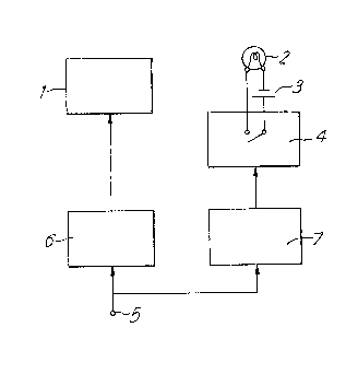
to a minimum. The circuitry comprises a display 1
controlled via a conventional display driver 6 from
other equipment (not shown) such as a microprocessor.
Whenever the display is changed a signal is sent also
to a timer circuit 7 which triggers, and passes a
control signal to an electronic switch 4 which in turn
passes power from a battery 3 to a lamp 2. The lamp
2 is arranged to illuminate the display 1. After a
preset period, the timer circuit 7 sends a further
control signal to the switch 4 to switch lamp 2 off.
Figure 1.

Revendications

Note : Les revendications sont présentées dans la langue officielle dans laquelle elles ont été soumises.


-6-
CLAIMS
1. Electronic equipment including a display and
characterised by means for illuminating said display,
and means controlling said illuminating means for
switching on the illumination only as a result of the
occurrence of a change in the display.
2. Electronic equipment as claimed in claim 1
wherein the display is not intrinsically illuminated.
3. Electronic equipment as claimed in claim 2
wherein the display is an LCD display.
4. Electronic equipment as claimed in any one of
claims 1 to 3 wherein said controlling means comprises
means for detecting the occurrence of a display
change, and outputting a control signal as a result of
such change, and switch means, controlled by said
control signal, for switching said illuminating means
on.
5. Electronic equipment as claimed in claim 4
wherein said detecting means forms part of a
microprocessor which also controls the display itself.
6. Electronic equipment as claimed in any one of
the preceding claims further comprising a timer for
controlling the time for which said illuminating means
is switched on.
7. Electronic equipment as claimed in either one
of claims 4 or 5, and claim 6 wherein said timer is
controlled so as to commence timing upon switching on
of the illuminating means, and to output a further
control signal to said switch means after a preset
period to switch said illuminating means off.
8. Electronic equipment as claimed in claim 7
wherein said timer forms part of said microprocessor.
9. Electronic equipment as claimed in any one of
the preceding claims, which is battery powered.

Description

Note : Les descriptions sont présentées dans la langue officielle dans laquelle elles ont été soumises.

2 ~i
"IhLUMINATION OF DISPLAYS"
This invention relates to illumination of
displays, and is particularly directed to illumination
of displays which are not intr:Lnsically illuminated,
such as LCD displays.
Displays are, by and large, meant to be
readily seen and understood by a user. Many displays
are intrinsically illuminated and do not usually need
further illumination. However, some displays, the
most obvious example beiny LCD displays, are not in
themselves illuminated and, in the absence of a
reasonably strong ambient light, need a background
illumination if they are to be easily seen by a user.
This invention concerns an improved means of providing
such illumination, as well as providing additional
illumination to displays whose inherent illumination
is not sufficient to be easily seen.
A common means of providing such illumination
is by way of a separate light, for example a
backlight, which is switched on or off according to
need. Where power consumption is not a problem such
lighting may be permanently switched on; where power
needs to be conserved, for example in battery-operated
equipment, switch means may be provided to enable the
user to manually switch on the light when needed
either momentarily, or for a fixed duration.
In the present invention, a further
improvement in battery consumption is achieved by
providing means for enabling the light only as a
result of a change of display. Preferably, once
enabled, the light will remain enabled for a pre-
determined duration. It will be noted that the
control of the light is independent of the source or
cause of the display change - i.e. whether as a result
of user actions or otherwise.

o ,~ ~3
-- 2
The invention finds particular application in
cases where the power consumption is critical - for
e~ample portable equipment - and which may receive
display changing information, such as messages,
without any user interaction. User actions will also
in general enable the display light via the same
mechanism by virtue of the upclating of the display
caused by the users input.
In order that the inverltion may be better
understood, an embodiment thereof will now be
described by way of example on].y, and with reference
to the accompanying drawings irl which:
Fiyure 1 is a block diagram of a display unit
incorporating an illuminating light according to the
invention;
Figure 2 is a view similar to Figure 1, but
showing the particular application of the invention to
a cordless telephone; and
Figure 3 is a diagram of the controlling logic
within the rnicroprocessor ~orming part of the cordless
telephone of Figure 2.
Referring to Figure 1, the display to be
illuminated is represented by the reference 1. This
will be a display which either has no inherent
illumination, or one whose illumination needs boosting
for ease of viewing. The lamp which carries out the
necessary illumination is shown under reference 2, and
may be any type of light source suitable for the
purpose. The lamp is connected to a battery 3 via an
3o electronic switch 4. The battery may be a dedicated
battery, or it may be the main battery supplying power
to the remaining circuits.
The display input signal is applied at a
terminal 5, and is input to a display driver 6 which
drives the displa~ 1 in the usual manner. The input
signal is also passed to a timer circuit 7 which

_ 3 _ 2~g~ 3~L3
triggers when any change is detected .in the display
input signal, and passes a control slgnal to the
electronic switch 4 to close same and thus allow
current to pass from the battery 3 to the larnp 2.
The period for which the switch 4 is closed, and hence
the lamp 2 illuminated, is set by the timer circuit 7.
The period is set to an amount which is judged to be
suf~icient for the particular display, and the
circumstances of use.
Referring now to Figures 2 and 3 there will be
described the particular application of the present
invention to a cordless telephone system. Such
systems generall~ comprise one or more base units
which are hard wired to the telephone network, and a
plurality of portable units or handsets. The base
units and the portable units each contain transceivers
by which the portable units may communicate with the
base units. Figure 2 is a simplified block diagram
of the circuitry of a typical portable unit forming
part of such a system. The portable unit comprises
an earpiece 8 and microphone 9 by which a user can
exchange messages in the manner of a conventional
telephone. A keypad matrix 10 is provided to enable
the user to key in the numbers and/or functions that
are required. The keypad matrix 10 communicates via
parallel leads 11 with a microprocessor 12 which
controls the operations of the portable unit in a
manner which is known, and will not be explained
further. Control is passed from the microprocessor
to a conventional modem and control unit 13 which in
turn controls a transceiver 14 and audio circuitry 15.
The transceiver 14 deals with the transmission and
reception, via an aerial 16, of the radio signals
between the porta~le unit and the base unit (not
shown). The audio circuitry 15 handles the signals
to and from the earpiece 8 and the microphone 9.

2 ~ 2 ~
_ 4 -
These operations are well known, and will not be
described further.
The portable unit is equipped with an LCD
display 17 which is fed in the usual manner from the
microprocessor 12 via a conventional display driver
18. In order to illuminate the display 17, a display
backlight 19 is provided in the manner described above
with reference to Figure 1. Power for the backlight
19 is taken from the system battery (not shown) via a
switching power supply unit (P',U) 10. The power
supply unit 20 is in turn controlled from the
microprocessor via a control lead 21.
In operation, the backliyht 19 is switched on
whenever a display change occurs, and remains on for a
preset period, in this case 10 seconds. Both display
change detection and backlight timing are controlled
from within the microprocessor 12 and Figure 3
illustrates the logic which is used to effect the two
functions. The diagram is self-explanatory and will
not be explained in detail. The timer and the
software-based control process scheduler both form
part of the microprocessor 12. The microprocessor
12, in its role in controlling the normal functions of
the portable unit, has many tasks to perform in
addition to control of the backlight; thus the
references to "Return" in Figure 3 mean simply that
the microprocessor 12 returns to its normal functions
whilst periodically monitoring for an event effecting
the backlight.
The above-described invention will find a
variety of applications in portable equipment,
particularly that which is of physically small size
and therefore of limited battery capacity. The
particular application which has been described~
namely the illumination of the display in the handset
of portable telephone equipment is kut one example

2 ~
of the many applications to which the invention may
be applied.

Dessin représentatif
Une figure unique qui représente un dessin illustrant l'invention.
États administratifs

2024-08-01 : Dans le cadre de la transition vers les Brevets de nouvelle génération (BNG), la base de données sur les brevets canadiens (BDBC) contient désormais un Historique d'événement plus détaillé, qui reproduit le Journal des événements de notre nouvelle solution interne.

Veuillez noter que les événements débutant par « Inactive : » se réfèrent à des événements qui ne sont plus utilisés dans notre nouvelle solution interne.

Pour une meilleure compréhension de l'état de la demande ou brevet qui figure sur cette page, la rubrique Mise en garde , et les descriptions de Brevet , Historique d'événement , Taxes périodiques et Historique des paiements devraient être consultées.

Historique d'événement

Description Date
Inactive : CIB de MCD 2006-03-11
Demande non rétablie avant l'échéance 1999-03-26
Inactive : Morte - Aucune rép. dem. par.30(2) Règles 1999-03-26
Réputée abandonnée - omission de répondre à un avis sur les taxes pour le maintien en état 1998-11-27
Inactive : Renseign. sur l'état - Complets dès date d'ent. journ. 1998-06-19
Inactive : Abandon. - Aucune rép dem par.30(2) Règles 1998-03-26
Inactive : Dem. de l'examinateur par.30(2) Règles 1997-09-26
Exigences pour une requête d'examen - jugée conforme 1994-09-01
Toutes les exigences pour l'examen - jugée conforme 1994-09-01
Demande publiée (accessible au public) 1993-05-29

Historique d'abandonnement

Date d'abandonnement Raison Date de rétablissement
1998-11-27

Taxes périodiques

Le dernier paiement a été reçu le 1997-11-06

Avis : Si le paiement en totalité n'a pas été reçu au plus tard à la date indiquée, une taxe supplémentaire peut être imposée, soit une des taxes suivantes :

  • taxe de rétablissement ;
  • taxe pour paiement en souffrance ; ou
  • taxe additionnelle pour le renversement d'une péremption réputée.

Veuillez vous référer à la page web des taxes sur les brevets de l'OPIC pour voir tous les montants actuels des taxes.

Historique des taxes

Type de taxes Anniversaire Échéance Date payée
TM (demande, 5e anniv.) - générale 05 1997-11-27 1997-11-06
Titulaires au dossier

Les titulaires actuels et antérieures au dossier sont affichés en ordre alphabétique.

Titulaires actuels au dossier
AT&T WIRELESS COMMUNICATIONS PRODUCTS LTD.
Titulaires antérieures au dossier
GRAHAM EDGAR BEESLEY
Les propriétaires antérieurs qui ne figurent pas dans la liste des « Propriétaires au dossier » apparaîtront dans d'autres documents au dossier.
Documents

Pour visionner les fichiers sélectionnés, entrer le code reCAPTCHA :


Pour visualiser une image, cliquer sur un lien dans la colonne description du document. Pour télécharger l'image (les images), cliquer l'une ou plusieurs cases à cocher dans la première colonne et ensuite cliquer sur le bouton "Télécharger sélection en format PDF (archive Zip)" ou le bouton "Télécharger sélection (en un fichier PDF fusionné)".

Liste des documents de brevet publiés et non publiés sur la BDBC .

Si vous avez des difficultés à accéder au contenu, veuillez communiquer avec le Centre de services à la clientèle au 1-866-997-1936, ou envoyer un courriel au Centre de service à la clientèle de l'OPIC.


Description du
Document 
Date
(aaaa-mm-jj) 
Nombre de pages   Taille de l'image (Ko) 
Dessins 1993-05-29 2 36
Page couverture 1993-05-29 1 14
Abrégé 1993-05-29 1 21
Revendications 1993-05-29 1 39
Description 1993-05-29 5 164
Dessin représentatif 1999-08-03 1 5
Courtoisie - Lettre d'abandon (R30(2)) 1998-09-23 1 171
Courtoisie - Lettre d'abandon (taxe de maintien en état) 1998-12-29 1 184
Taxes 1995-10-24 1 39
Taxes 1996-10-22 1 81
Taxes 1994-10-19 1 52
Courtoisie - Lettre du bureau 1994-10-04 1 39
Correspondance de la poursuite 1994-09-01 1 43
Demande de l'examinateur 1997-09-26 2 42