Note: Descriptions are shown in the official language in which they were submitted.
r
208~10~ ~
DOWNI)RAFT GAS RANGE
WITE~ SEi~T Fn BURN~I~ SYSTEM
Field of the Tnventiol~
This invention relates to gas ranges including
a downdraft exhaust fl~r the cooking surface and,
more particularly, relates to a sealed gas burner
6y6tem f or downdraf t ~-anges to provide a variable,
forced air-gas mixture for cooking.
Backq~ound Q~ the Invention
Gas ranges typically use atmospheric burners.
Such atmospheric burners perform well when a
plentiful supply of secondary air surrounds the
burner. Typically, s;3condary air is supplied in
such ranges thrGugh olle or more aeration openings in
the burner pan :iuLL-Iullding the burner body. In
addition, secondary a ir is often supplied through a
central opening in the burner. Sucll openings,
however, create problems in the use of gas ranges
because they permit spills, boilovers and the like
to run from the top of the gas range into its
interior, creating an undesirable cleaning problem.
Furthermore, com}~ustion of any fuel, including
natural gas and the other gas fuels that are used in
household gas ranges, generally results in
undesirable byproducts such as carbon monoxide (CO)
and oxides of nitrogell (NOI). These pollutants are
not direct products of perfect combustion but
generally result from incomplete combustion and the
presence of secondary air. Efforts to protect the
environment have resu] ted in legislation and
standards to limit permissible levels of such
pollutants in both the United States and Europe, and
it is expected that such legislation will become
more widespread and t}lat the resulting standards
-1- ~L
2~8~
will become more stringent. It is clearly desirable
to avoid the generation and distribution of such
pollutants during the operation of gas ranges in the
household of a user, and various apparatus have been
proposed to reduce the generation and distribution
of pollutants in the operation of gas burners.
As indicated abo~e, it is desirable that the
range top be gealed to preclude liquids and
materials from entering the interior of the range.
Some sealed, smooth-top gas ranges have included
blowers or fans to produce both a flow of combustion
air to, and an exhaust of combustion products from,
burners that are located under a sealed glass or
ceramic top of the range . See U. S . Patent Nos .
2,870,829; 3,404,350; 3,870,457; 3,968,785; and
4, 020, 821. For example, U. S. Patent No. 4, 020, 821
to Reid, Jr. et al, discloses a gas burning range
with a sealed, smooth, glass or ceramic top lying
over a plurality of infrared burners. In the gas
range of Reid, Jr. et al., a primary gas/air mixture
i5 provided for each burner from a combined gas and
air shutter valve to a burner tip for combustion. A
blower creates a negative pressure in each burner
and throughout the flow path for the fuel gas, draws
a flow of additional air for combustion into the gas
f low path, and creates an exhaust f or the combustion
products leaving the burners. Such sealed top
ranges generally rely on infrared heating of cooking
utensils through the sealed top and are thus not as
thermally efficient or as fast as open flame ranges.
Sealed top gas ranges with open f lame burners
have been obtained by, for example, sealing the
burner head to the top range surface or burner pan.
The use of such "sealed burners" in gas range
3 5 construction eliminates the openings through which
--2--
2asso~l
secondary air reaches the burners, and the air
needed for combustion must enter the combustion zone
in a path which is below the existing products of
combustion, and the pcrformance of the range burners
is vulnerable to a nul~ber of adverse effects. Among
the problems presented by such open flame, sealed
burner constructions are the recirculation of
products of combustioll, the tendency of the gas
flames to "reach" for combustion air which distorts
o the flame pattern and detracts from even heat
distribution, the desl:ruction of f lame patterns as a
result of adjacent walls that interfere or divert
the secondary air supl~ly, and flame distortion
created by the simultaneous operation of adjacent
burners that compete for secondary air as their
flames tend to be dra~in toward the natural thermal
updraft of the adjacent burners. Attempts to solve
such problems have included high grate tops and
other barriers seeking to prevent such burner
interaction.
Gas ranges with c~owndraft exhaust systems are
known, as shown, for example, by U. S. Patent Nos.
4,413,610; 4,413,611; 4,409,954; 4,457,293; and
4 , 7 5 0 , 4 5 0 .
The problems attendant sealed ~urners are
compounded in gas ranges with downdraft exhausts.
The purpose of the do~mdraft exhaust is, of course,
to remove products of combustion and cooking vapors
from the gas range during its operation by creating
a flow of exhaust air across the top of the range
adjacent the burners. The air flow from such a
forced exhaust pulls the flames in the direction of
the exhaust, interfering with proper combustion and
heat distribution at the burners . The air f 14w
created by the downdraft exhaust means also pulls
--3--
2~L051
the secondary air awa~ from the burner flames, and
the disturbed f lame cones impinge on relatively cold
grate f ingers to cause incomplete combustion . In
some designs, heat from the burners of a downdraft
gas range has been so unevenly distrilbuted that it
is not possible to ev~nly cook such foodstuffs as
pAnr:lk~c ~ eggs and sa~lsages in a large skillet. In
addition, a low simmer flame cannot be
satisfactorily stabili zed and ignition of the flame
becomes unreliable.
Prior efforts to combine open flame sealed
burners with a downdraft exhaust have also used
shields extending several inches above the burner to
help protect the burner f lame from the exhaust f low.
Other attempts have elevated the entrance to the
downdraft exhaust plenum several inches above the
cooktop in an effort to minimize the adverse effect
of the exhaust at the cooktop surface. In still
further efforts, the diowndraft exhaust has been
reduced in power, or the entrance to the downdraft
plenum has been remot~ly located from the burners,
or has been reduced in! intake area, in attempts to
minimize the adverse effect of the exhaust. Each of
these methods, however, detracts from the
effectiveness of the downdraft exhaust and reduces
its ability to capture and remove cooking vapors,
odors, heat and other products of combustion and
cooking .
The use of powered gas burners in gas cooking
ranges has been disclosed in the art. For example,
U.S. Patent Nos. 3,468,298 to Teague, Jr. et al.
discloses a sealed, smooth-top gas range with a
plurality of powered infrared burners. In the gas
range of Teague, Jr. et al, a blower supplies air to
and pressurizes a manifold extending along the front
--4--
8 2~84D~
of the range. The marlifold has openings formed in
its bottom, one for each of the plurality of
burners. A slide val~e for each burner includes air
control orifices cooperating with a manifold opening
for each burner to permit a variable and
controllable flow of combustion air from the
manifold into a separclte valve manifold, and from
the separate valve manifold through a venturi mixer
to its associated burller . Gas f low to the venturi
mixer and burner is controlled by a diaphragm-
operated gas f low reglllator, which is operated by
the air pressure in t~1e valve manifold to control
the gas/air mixture to each burner.
U. S . Patent No. ~, 569, 328 to Shukla et al.
seeks to avoid emission of air pollutants, such as
carbon monoxide and o:cides of nitrogen, into the
kitchen. The Shukla et al. patent discloses a gas
range with a ceramic l:ile forming a plurality of
openings provided, pr~ferably, with a forced air-gas
mixture and adapted to provide an open standing
f lame close to its upl~er surf ace so that the ceramic
tile burner will provide high radiant heat as a
result of the gas flallle. In Shukla et al. 's
invention, a jet plate is positioned between the
infrared burner and the supporting surface for the
cooking utensil. The jet plate is stated to be of
considerable importance in the achievement of high
thermal efficiencies. Shukla et al. 's jet plate
includes a plurality ~f perforations or jet holes to
form high velocity gas jets from the combustion
products of the inf rared burner, and the gas j ets
are directed to impinge against and convectively
heat the lower surface of the cooking utensil and
then pass into the at]nosphere of the kitchen above
the cooktop.
--5--
208~0~1
While Shukla et al. discloses that his ceramic
tile may operate as arl atmospheric burner, in Shukla
et al. 's preferred embodiment, a blower is
positioned in the central portion of the range to
pressurize an air plerlum, which is linked to a
plurality of mixing v211ve assemblies to control the
flow of the forced air-gas mixture to the plurality
of burners. Each mixi ng valve assembly provides a
selected stoichoimetr~ for its assoriated burner by
mechanically coupling a rotatable air orifice plate
to a gas valve shaft 80 that by rotation of the gas
valve shaft to contro] gas flow, air flow is
simultaneously contro] led by the alignment of one or
more of several discrete openings in the air orif ice
plate with a fixed opening in an air flow tube.
U.S. Patent No. 4,960,377 to Nunes et al.
discloses a gas-air mi xing valve for use with
residential and commercial cooking ranges. The
Nunes et al. valve is designed for use preferably in
a gas range having a plurality of gas burners. The
Nunes et al. valve is attached to an air plenum
which is pressurized ~y an air blower. The Nunes et
al. valve is adapted to be mounted over a hole
formed in the air plenum and to provide two valve
openings communicating with the interior of the air
plenum, one of the valve openings forming an inlet
to an air-gas mixing chamber within the valve, and
the other valve openirlg communicating with
atmosphere. The two ~ralve openings to the
pLes,,uLized air plenunt formed by the Nunes et al.
valve are covered by el rotating orif ice plate. The
rotating orif ice plate includes an opening
cooperating with the opening between the air plenum
and the air-gas mixincJ chamber, and an opening
cooperating with the opening to atmosphere so that
--6--
2084051
as the size of the en1:rance to the air-gas mixing
chamber is increased by rotation of the orif ice
plate, the size of the opening between the air
plenum and al ~'-re is correspondingly decreased
to maintain a constan1: air flow in the plenum for
the operation of each of the gas burners. As the
orifice plate is rota1:ed, the gas valve is also
operated to maintain a~ selected forced air-gas
mixture to each cookillg burner.
Other arrangemen1:s of gas ranges with power
burners, and air/gas control valves for gas ranges
with power burners are disclosed in U. S . Patent Nos .
3,162,237; 3,169,871; 3,371,699; 3,592,180;
4,622,946; and 4,794,'307. Notwithstanding these
various developments, the use of powered surface
burners is rare in hollsehold gas ranges. Variations
in the characteristics and burning properties of gas
from utility to utility and locale to locale have
made it dif f icult to achieve reliable and repeatable
combustion characteristics with powered surface
burners in a househol~1 range.
Other patents disclosing sealed burners include
British Patent Nos. 1,443,553; and 1,543,618; and
U.S. Patent Nos. 4,5113,346; 4,565,523; 4,570,610;
4,690,636; 4,757,801; 4,773,383; 4,971,024; and
5,046,477.
Notwithstanding lche efforts of others, no one,
prior to this inventil~n has provided a gas range
with the combined advantages and abilities of a
sealed top construction, downdraft exhaust and
powered open f lame gas burners .
SummarY of the Tnvention
The invention provides a th.orr-l ly efficient
sealed gas range with a downdraft exhaust combined
--7--
~g4~
with an open flame gas burner that limits the
generation of CO and NO~, is substantially immune to
the adverse effects o~' the downdraft exhaust and of
adjacent walls, and provides even heat distribution
with and without the downdraf t exhaust . Gas ranges
of the invention feat~lre good combustion, ignition
and re-ignition with ] ow levels of generated CO and
NO~, a high turndown ratio with a stable low flame
setting, a high thermcll efficiency at least equal to
existing atmospheric c~as ranges, a large entrance to
the downdraft exhaust substantially flush with the
cooktop and located erfectively adjacent the
burners, freedom from surface barriers or shields
which inhibit the effectiveness of the downdraft
exhaust, and immunity from adjacent walls, providing
greater freedom in installation of the range.
The invention pr~vides a gas range including a
top surface adapted to be sealed to a gas burner
as6embly, and a downd~^aft plenum adjacent the gas
2 0 burner assembly adapted to draw cooking vapors, heat
and the products of combustion and cooking from
adjacent the surface of the range and the gas burner
assembly, and a sealed, powered gas burner assembly
comprising a gas burnl~r and a combined air and gas
supply means adapted for connection with an air flow
source and a gas f low source to provide a
combustible gas-air mixture to a sealed conduit
connected between the gas burner and the combined
air and gas f low supply means . The combined air and
gas flow supply means combines flows of primary
combustion air and ga.s from their respective sources
and controls the air :Elow and gas f low to provide a
burning gas/air jet at each burner outlet with
rapid, substantially ,~omplete combustion in a short,
stable flame which is unaffected by such outside
--8--
~ 208~0~1
influences as the downdraft exhaust. The means for
providing a combined a ir f low and ga8 f low can
comprise a mixing manifold between the sealed
conduit and alr and gas flow sources, with control
means providing a controlled flow of air and gas
from the manifold to the sealed conduit. In
preferred embodiments, the control means can further
comprise separate air f low and gas f low control
valves between the mixing manifold and the sources
of air flow and gas flow respectively.
The invention provides a method of cooking with
gas and a downdraft exhaust by directing a
controllable f 14w of combustion air through a f irst
conduit and a controllable flow of gas through a
second conduit, mixing the controllable flows of
combustion air and gas to provide a directed
combu6tible f low of air and gas through a third
sealed conduit to the gas burner, controlling the
f lows of combustion air and gas to provide a
controlled variable combustion of ga6 at the gas
burner, combusting the directed f low of combustion
air and gas from the gas burner for cooking and
exhausting gaseous combustion and cooking byproducts
by providing a downdraft adjacent the gas burner.
In the invention, a powered flow of primary
combustion air and gas flow are provided from within
each of the plurality of burner outlets to form
combusting gas/air jets with rapid and substantially
complete combustion close to the burner outlets, in
short, stable flames which are unaffected by the
downdraft exhaust and other outside influences and
provide even heat distribution.
Other f eatures and advantages of this invention
will be apparent from the drawings and description
that follow.
_g_
2~8~0~1
Brief Descril~tion of ~he Drawint~s
Flg. 1 is a diagrammatic partial cross-
sectional drawing of a gas range of this invention
to illustrate the invention;
Fig. 2 is a diag]-ammatic partial cross-section
of a combined air and gas f low supply means of Fig .
l;
Fig. 3 is a top 1Jiew of Fig. 2 taken at a plane
through line 3-3 of Fig. 2;
Fig. 4 is a partially broken-away perspective
view of a pref erred combined air and gas f low supply
means of this inventit~n; and
Fig. 4A is a siml~lif ied view of the air f low
control plate and orifice of the combined air and
gas ~low supply means of Fig. 4.
Bes~ Node o~ the Inver~tion
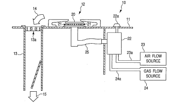
Fig. 1 is a schematic, partially cross-
sectional diagram of a downdraft gas range of the
invention. As shown in Fig. 1, the gas range 10
includes a cooktop ha~ring a top surf ace 11 adapted
to be sealed to a gas burner assembly 12. The range
10 further includes a downdraft plenum 13 with an
entrance 13a adjacent the gas burner assembly 12. A
downdraft plenum 13 is connected with an exhaust
blower (not shown). ~rhen the exhaust blower is
operated, the downdraft plenum 13 withdraws air and
cooking vapors from adjacent the top surface 11 and
gas burner assembly 12 of the range, as indicated by
arrows 14 and 15. The sealed gas burner assembly 12
includes a gas burner 20 having a plurality of
burner outlets 21, a combined air and gas flow
supply means 22 adapted for connection with an air
flow source 23 and a gas flow source 24. A sealed
conduit 25 is connected between the gas burner 20
--10--
20$~0~1
and the combined air and gas flow supply means 22
and a variable 6upply of a combustible mixture of
gas and air to burner 20 is controlled by knob or
handle 22a. The combiLned air and gas flow supply
means 22 includes means for combining the flows of
air and gas and means for controlling the air flow
and gas flow to provide a combined flow of air and
gas through the condui t 25 and the gas burner
outlets 21 for contro] lable combustion.
As shown in Fig. 2, the air and gas flow supply
means 22 for providing a combined air flow and gas
flow includes a mixing manifold or plenum 26 between
the sealed conduit 25 and the air flow and gas flow
sources 23 and 24, respectively. The air and gas
flow supply means 22 also provides control means 27
for providing a controlled flow of both air and gas
from the manifold 26 to the sealed conduit 25. As
shown in Fig. 2, the control means 27 comprises a
separate air flow control means 31 between the air
flow source 23 and the manifold 26 and a separate
gas control valve 32 between the gas flow source 24
and the manifold 26.
In the embodiment of the combined air f low and
gas f low supply means 22 that is shown in Figs . 2
and 3, air flow from air flow source 23 is directed
to a large reservoir 3 4 in communication with the
manifold or plenum 26. Air flow control means 31 is
formed by a rotating air flow control plate 35 and
an air flow opening 36 formed in the manifold 26.
3 0 As indicated in Fig . 2 and shown in Fig . 3, the air
flow control plate 35 includes a shaped flow control
orifice 35a and lies adjacent to and over the air
flow orifice 36. By rotating the air flow control
plate 35 clockwise in Fig. 3, the air flow opening
36 becomes ~Io~L~ssively less blocked by the flow
--11--
20840~1
control orifice 35a of' air flow control plate 35
thereby controlling the air flow, indicated by arrow
37 in Fig. 2, from the air flow source 23 to the
manifold or plenum 26 through air flow opening 36.
As shown in Fig. 2, the air flow control plate 35 is
mounted on an actuator shaft 38 which also controls
the gas f low control valve 32 . By rotation of the
knob or handle 22a, a user of the range may
simultaneously control the gas flow through gas flow
control valve 32 from the gas flow source 24 into
injector 41 and conduit 25, and the air flow from
air source 23 through air flow opening 36 into
manifold 26, injector 41 and conduit 25.
As indicated in Fig. 2, the manifold 26
includes an injector 41. Gas flow from the gas flow
control valve 32, indi cated by arrow 42, induces the
flow of air, indicated by arrows 43 and 44, through
injector openings 41a and 41b for mixing with the
gas flow 42. The com})ined air flow and gas flow are
directed by injector 41 into the sealed conduit 25
f or direction to the gas burner 2 0 and through the
gas burner outlets 21 (shown in Fig. 1). Air flow
source 23, preferably, includes a small air blower
providing a controlla~)le flow of air to air
reservoir 34.
Fig. 4 is a partially cut-away, perspective
view of a preferred embodiment of the combined air
and gas flow supply means 22 which is construGted in
a manner similar to that indicated in Figs. 2 and 3
but is adapted for manufacture and for use in a
household downdraft gas range. The structure shown
in Fig. 4 is adapted for a gas range with a
plurality of gas burners; however, the elements of
the Fig . 4 Pmhorl; r ~ that correspond to the
--12--
~840~1
elements illustrated in Figs. 1-3 carry the same
element numbers.
In the structure shown in Fig. 4, the range top
surface 11 (partially broken away) which carries a
plurality of gas burners 20 is fastened to a sheet
metal weldment 50 which forms a burner box, as is
well known in the art, and houses a plurality of
sealed conduits 25 whi!ch lead to the plurality of
gas burners 20 (not s~lown in Fig. 4~ sealed to
surface 11. The mixing manifold or plenum 26 for
each of the plurality of gas burners may be formed
by an injection box molding 51. For ease of
assembly, the injection box 51 may be molded to form
a plurality of plenum--forming cavities 26 so that
when the injection bo~: 51 is fastened to the side
wall 50a (partially broken away) of the burner box
50, as indicated in Fig. 4, it forms a manifold, or
plenum, 26 for each of the gas burners. As
indicated in Fig. 4, the injection box 51 may be
molded to include a p] urality of bores 52 to permit
it to be fastened to the burner box 50 by screws 53
as indicated in Fig. 4. The injection box 51 may
also be formed with c~lannels 54, one surrounding
each plenum-forming cavity 26, in the face which
mates the wall 50a of the burner bo~ 50. The
rh~nnPl ~ 54 are adapted to carry o-ring seals so
that upon assembly of the injection box 51 to the
wall 50a of the burner box 50, the plenum-forming
cavities 2 6 are sealed .
In addition, as shown in Fig. 4, the top of the
injection box may be provided with a plurality of
tongue and grooved portions 55 to permit a mating
plate 56 which carries the air flow opening 36, to
be inserted into and carried by the injection box
51. By molding the injection box 51, it may be
--13--
208~
economically provided with a number of other
features, such as formed grooves 57 and tonguefi (not
shown) in their sides so that each injection box 51
can be molded with a E)air of plenum-forming cavities
26, but can provide tongue and groove assembly with
another injection box, end-to-end in a row,
permitting simple assembly for gas range5 with 2, 4
and 6 gas burners.
As indicated in Fig. 4, the injection box 51
forming a manifold, or plenum, 26 is carried within
a large reservoir or air plenum 34 which is formed
by a plurality of she~t metal wall portions carried
by the burner box 50. For example, the larger
reservoir 34 can be fcrmed by a partial side wall
60, a piece of sheet metal 61 formed to provide side
and back walls, a sheet metal top 62 and a sheet
metal bottom 63. The reservoir 34 is connected with
an air flow source 23 (see Figs. 1 and 2). The
plenum forming injection box 51 is carried within
the reservoir 34 by the burner box, and the
injection box 51 carries at its back a plurality of
gas flow control valves 32 which are also within the
reservoir 34 . The gas f low control valves 32 are
connected from within the reservoir 34 to a gas flow
source 24 (not shown in Fig. 4) by conduits as
indicated in Figs . 1 and 2 . Gas f low to the gas
burners is varied by rotating the actuator shafts 38
for the gas flow valves 32. As shown in Fig. 4, an
air flow control plate 35 is carried on each of the
actuators 38 immediateiy adjacent the plate 56
forming the air flow orifice 36. Fig. 4A is a view
from above Fig. 4 showing the air control plate 35
and the cooperatively shaped air flow orifice 36.
As shown in Fig. 4A, the air flow control plates or
cams 35 have cam-like shapes of varying outer radii
--14--
' 2~0~1
which are adapted to coact with the cooperatively
shaped air flow openings or orifices 36 and provide
variably-sized air flow openings and controlled air
f lows into the plenum~ 2 6 to provide a stable
effective combustion of the variable gas flow to the
burner 20, which is controlled by gas flow control
valve 32 as a result of adjustment of the common
actuator shaf t 3 8 .
In operation, a variable gas flow is directed
into the injector 41 ~ithin plenum 26 from the gas
f low control valve 32 . A controlled f low of air i5
injected into the gas flow through injector openings
41a and 41b within the plenum 26. The combined air
and gas flow is directed from the injector into the
sealed conduit 25 leading to the gas burners 20. As
indicated in Fig. 4, the reservoir 34 may be sealed
at the openings provided for actuator shafts 38 with
the plurality of grommets 65, the injector openings
provided in the wall 50a of the burner box may be
sealed against the plurality of injectors by
grommets 64, and the injectors 41 may be sealed with
the sealed conduits 25 by an O-ring seal 66 carried
by the injectors 41.
In the invention, a variable flow of gas for
open flame cooking, at rates permitting a slow
simmer as well as rapid heating, is combined with an
accurate and controllable variable air flow at rates
desirable for effective, substantially complete
combustion of the gas with a substantially reduced
need for secondary combustion air, and the
accurately combined ga~/air mixture is delivered to
the burner outlets 21 through a sealed conduit 25
thereby preventing dil~ltion and variation of the
desired combustible mixtures, limiting the
undesirable generation of CO and N0~ and preventing
--15--
1 ~08~0~1
operation of the downdraft exhaust from affecting
the desired combustibl e mixture . The burner outlets
or ports of the standard burner preferred for use in
the invention have standard diameters of about 0 . 05
to about 0 .15 inch and pref erably relatively long
bore lengths having a substantial fraction of an
inch, for example, abcut 0.312 to about 0.343 inch.
one such ~urner may have, for example, a ~irst ring
of 18 ports with a diameter of 0.142 inch, and 6
ports with a diameter of 0. 079 inch, all with a bore
length in the above range. The burner may also have
a second ring of 16 ports with a diameter of 0 . 051
inch and a bore length of 0 . 060 inch spaced below
the f irst ring . The combination of such burner
outlets with relatively high air f low rates,
providing, for example, a substantial percentage of
the combustion air needed, improve burner operation.
orifices or ports formed with thin walls, such as
0.030 inch arR not preferred. Furthermore, the
combination of a burner provided with gas flow and a
desirable high percentage rate of combustion air
flow through a sealed conduit (thereby substantially
reducing the burners need for secondary airl and an
effective adjacent downdraft exhaust provides a
household gas range which can substantially free the
household of undesirable pollutants.
In the invention, a powered f low of combustion
air and a gas flow are provided from within each
burner outlet to form combusting gas/air jets with
rapid and substantially complete combustion of the
gas close to the burner outlets in short, stable
flames which are unaffQcted by the downdraft exhaust
and other outside influences and provide even heat
distribution around the burner. The resulting
flames are believed to be impervious to the
-lG-
2084051
downdraft exhaust and other such outside influences
because of the resultlng "structural integrity" of
the rapidly moving gas/air jet and its rapid,
substantially complet~ combustion. For example,
with the preferred burners and burner outlets
described above, clearl, sharp, stable flames can be
obtained, providing even heat distribution as high
as 10000 BTUE~ with a gas pressure of about 5 inches
of water column pres:,ulL~ above atmospheric pressure,
and with an estimated primary air flow rate in
excess of about 70 to about 85 cubic feet per hour
and preferably in exc~ss of 85 cubic feet per hour.
Thus, the invention permits effective cooking
with a gas burner and downdraft exhaust by directing
a controllable flow of combustion air through a
first conduit 23a, directing a controllable flow of
gas through a second conduit 24a, mixing the
controllable flows of combustion air and gas to
provide a directed flow of combustion air and gas
through a third sealed conduit 25 to a gas burner
20, controlling the flows of combustion air and gas
to provide a controllable variable combustion of gas
from the outlets 21 of gas burner 20, combusting the
directed flow of combusted air and gas at the gas
burner outlets 21 for cooking, and exhausting
gaseous combustion and cooking byproducts by
providing a downdraf t exhaust into plenum 13
adjacent the gas burne3~ 20.
In the method of l~he invention, the flows of
air and gas are preferably controlled before they
are mixed as shown in ]~igs. 2-4, but they may also
be controlled after they are mixed. The flows of
combustion air and gas are preferably passed through
at least one manifold or plenum 26 and are mixed in
a mixing head such as the injector 41. In the
--17--
2Q840Sl
method of the invention, the downdraft exhaust can
be urged into an entrance 13a in the sealed top 11
of the gas range adjacent the gas burner 20. The
directed flows of combustion air and gas are divided
at the gas burner into a plurality of flows for
combustion and the plurality of flows are given flow
rates and velocities that provide stable gas/air
jets, rapid and substantially complete combustion
and cooking flames that provide even heating in the
presence of the adjacent downdraft exhaust. The
method further includes control of the air flow, for
example by air flow control plate 35, to provide for
variable gas flows from gas flow valve 32 and an air
flow rate required to burn gas flow down to low
rates, for example, rates low enough to provide
s immering f ood stu f f s .
Thus, the method and apparatus of the invention
provides a plurality of flows of gas and combustion
air at the gas burner to direct a plurality of
easily ignited and stable flames with optimal flame
velocity and combustion to provide variable and even
heat generation substantially free of pollutants.
The invention permits the achievement of such
results with heat outputs from about 2000 BTUH to
about 12000 BTUH with larger burners and from 1500
BTUH to about 10000 BTUH with smaller burners. The
invention also provides a gas range which may be
operated so that the directed f low of air and gas is
provided only in the p]-esence of a downdraft
3 0 exhaust .
In one example of the invention, it was found
that heat was evenly distributed to a 10 inch black
cast-iron skillet, pernitting pancakes to be cooked
quickly with even donel~ess on all portions of the
skillet in the presence of a downdraEt exhaust
--18--
~08~
through an exhaust opening adjacent the gas burner
at a downdraft flow rate of approximately 300 cubic
f eet per minute throu~hout the system and a velocity
of 1,400 feet per min~lte at the exhaust opening.
The invention permitted the obtaining of clean,
sharp, stable flames ~Jith approximately 10,000 BTUH
output at about ~ inc~les of water column ~res~u
above atmospheric pressure.
While the description and drawings set forth
the currently known best mode of the invention,
other embodiments of the invention may be made
without departing fron~ the scope of the claims that
follow. Accordingly, the invention is to be limited
only by the scope of the claims and the prior art.
--19--