Note: Descriptions are shown in the official language in which they were submitted.
DISPLAY APPARATUS
The present invention relates to a display apparatus having a plurality
of display devices by which a single image is displayed.
Generally, with a display apparatus there are various factors which
determine visual comfort, such as brightness, contrast, whiteness, blackness,
color range, screen size, and other visual characteristics. Among various types
of display apparatuses, a liquid crystal display (LCD) apparatus is superior to
others in brightness, contrast, whiteness and blackness, considering its small
consumption of electricity and its ability to be driven by a low voltage. Moreover,
the LCD apparatus can relatively easily provide a color display. The LCD
apparatus can be constructed in a flat panel, and hence has an advantage that
the thickness (i.e., depth) of the apparatus can be made considerably smaller
than that of a conventional cathode ray tube (CRT). As a result, the LCD
apparatus is becoming more popular in various fields of use.
An LCD apparatus has a structure in which liquid crystal is confined
between a pair of substrates facing each other at a distance on the order of
microns and having transparent electrodes thereon. If fine dirt, dust or the like
is mixed into or becomes adhered to the inside of the apparatus during the
production process, the dirt or dust prevents the apparatus from operating
properly. In particular, faulty picture elements are more likely to occur. In
addition, due to the above-mentioned structure, a larger screen size has a higher
probability of there being faulty picture elements, i.e., the fault rate of a display
apparatus having a larger screen size is higher. In an LCD apparatus in which
such faulty picture elements occur, the display quality is largely deteriorated.Therefore, the LCD apparatus is disposed or discarded.
As described above, in an LCD apparatus, a larger screen size results
in a higher fault rate due to faulty picture elements. When the screen size is in
the order of 15 inches or larger, it is very difficult to mass-produce such an LCD
apparatus at reasonable production costs.
In order to overcome this problem, a plurality of minor LCD devices
having a screen size of 15 inches or smaller are arranged lengthwise and width-
3~
wise in an array pattern, so as to constitute a single LCD apparatus having a
large display area. An example is shown in Figure 1A. In Figure 1A, nine minor
LCD devices 1 are arranged in a 3 x 3 array. With this construction, if each
minor LCD device 1 is, for example, of a 14-inch square type, the screen size ofa resulting large-sized LCD apparatus 2 will be approximately 42 inches by 42
inches.
However, each of the minor LCD devices 1 have a non-image area 1 b
on which an image is not displayed along the periphery of a display area 1a on
which an image is displayed, as is shown in Figure 1B. For example, the non-
image area 1 b having a width of at least 3 millimeters (mm) is formed by a space
for containing the liquid crystal confined between the two opposing substrates,
and a space for disposing wiring and the like for applying a voltage to the minor
LCD device 1 so as to drive the picture elements.
Accordingly, as is shown in Figure 1A, the resulting LCD apparatus 2
has the non-image areas 1b in a shape of a lattice surrounding the respective
display areas 1a, i.e., the display area of the resulting LCD apparatus 2 is
discontinuous. As a result, the display quality is deteriorated and therefore the
displayed image cannot be entirely displayed and/or viewed.
In order to solve the problem mentioned above, a display apparatus
has been proposed in Japanese Patent Application No.3-293425 by the inventors
of the present invention. According to this display apparatus, a single display
area is formed by a plurality of display devices, and an image can be displayed
on the display area without discontinuity. A fundamental structure of such a
display apparatus is shown in Figure 2.
The proposed display apparatus includes, for example, two display
devices 11 and 12 provided with display areas 11a and 12a, respectively,
juxtaposed along a direction A, as is shown in Figure 2. To each of the display
areas 11a and 12a, end faces D of optical fiber bundles 3 for transmitting an
image are connected. On the other end faces C of the optical fiber bundles 3,
a composite image having no boundary area appears. Each optical fiber bundle
3 is made up of a plurality of parallel optical fibers 3' which are bent at an angle
~, at a predetermined point (a point E in Figure 2). In the display apparatus
3~
,.
shown in Figure 2, the display devices 11 and 12 are separately formed, but in
another case, display devices 13 and 14 may be adjacently formed, as is shown
in Figure 3.
In the display apparatus shown in Figure 2, an image signal
5 representing an image which is displayed on the display areas 11a and 12a of
the display devices 11 and 12 is introduced into the optical fiber bundles 3 at
their one end faces D, transmitted through the optical fiber bundles 3, and
emitted from the other end faces C.
A method of forming the optical fiber bundles 3 is now described.
10 First, as is shown in Figure 4, optical fibers 31 having the same length are
arranged side by side, and are then fastened to each other so as to form an
optical fiber sheet 32. Next, as is shown in Figure 5, the optical fiber sheet 32
is bent in a direction away from the arranged direction of the optical fibers 31 so
that the portions of the optical fiber sheet 32 on the sides of the introducing end
15 face D and the emitting end face C form an angle ~1. Thus, a bent optical fiber
sheet 33 is formed. A plurality of bent optical fiber sheets 33 are stacked in adirection in which the optical fiber sheet 32 is bent, so as to form the optical fiber
bundle 3 as a unit of the display area 11a or 12a.
Referring briefly to Figure 3, each optical fiber bundle 3 has an outward
20 facing slope 3c and an inward facing slope 3d on opposing side faces of the
stacked bent optical fiber sheets 32. The emitting end faces C of the optical
fibers 31 which form the optical fiber bundle 3 are made flat, and the optical
fibers 31 are arranged at regular pitches.
Figure 6 shows a partial sectional view of the optical fiber bundle 3.
25 Each of the optical fibers 31 making up the optical fiber bundle 3 has a coreportion 31a and a clad portion 31b which has a lower refractive index than that
of the core portion 31a. The optical fibers 31 are fixed to each other using a
suitable adhesive 34.
Finally, two optical fiber bundles 3 constructed in the above-described
30 manner are joined so as to form a display apparatus. At this time, the optical
fiber bundles 3 are joined so that the outward facing slopes 3c thereof do not
interfere with each other. For this reason, the optical fiber bundles 3 preferably
are joined such that vertical side faces 3e extending from the inward facing side
of the slopes 3d are connected.
With the above construction, a display apparatus having a display area
double the size of the display area 11a (12a) of one display device 11 (12) can
be obtained. The two display devices 11 and 12 are driven through a driving
circuit (not shown) using split signals. The split signals are obtained by splitting
an image signal for each frame into two signals, e.g., a corresponding signal for
the right and left fields. Therefore, the image appearing on the display areas 11 a
and 12a is displayed as a composite image on the emitting ends faces C of the
combined optical fiber bundles 3 without discontinuity.
The number of the display devices which are joined is not limited to
two, and a resulting display apparatus may be formed by three display devices
joined in a direction A, as is shown in Figure 7. In this display apparatus, an
optical fiber bundle 35 which is not bent is interposed and joined between the two
optical fiber bundles 3 which are bent in the same way as in the above example
having two display devices. With such a construction, a thin display apparatus
having a display area three times the size of a display area 15a (16a, 17a) of one
display device 15 (16, 17) is provided. However, it is diffcult to join four or more
optical fiber bundles 3 because the outward facing slopes 3c interfere with eachother. Also, it is difficult to add another optical fiber bundle 3 in a direction B
perpendicular to the direction A. If there exists no non-image area 1 b, a number
of display devices can be joined with each other. However, as described above,
since a resulting display apparatus unavoidably has the non-image areas 1b, it
is substantially impossible to realize such joining.
Regarding the bent angle ~, of the optical fiber bundle 3, when the
angle ~1 is small, a distance L (Figure 2) between the introducing end face D and
the emitting end face C is long. Therefore, the bent angle ~, must be large in
order to realize a thin display apparatus. However, according to the above-
described approach, it is difficult to make the bent angle ~, larger without
disordering the arrangement of the optical fibers 31.
In the above display apparatus, the emitting end face C of the optical
fiber bundles 3 for transmitting an image signal is flat, so that the viewing angle
corresponding to the emitting angle of the optical fiber bundle 3 is small. As aresult, the display apparatus has a disadvantage in that if the viewing angle with
respect to the display screen is changed only a little, the displayed image cannot
be seen.
There are methods for enlarging the viewing angle including a method
of roughening the emitting end face C of the optical fiber bundle 3, a method ofmaking the emitting end of each of the optical fibers 31 into a lens-like shape
(Japanese Laid-Open Patent Publication No. 60-169833), and a method of
disposing a scattering plate or a microlens array sheet on the emitting end faceC of the optical fiber bundle 3 (Japanese Laid-Open Patent Publication No. 1-
189616). However, although the viewing angle can be enlarged by the
roughening method for the optical fiber bundle 3 and the method of forming a
scattering plate, more ambient light is scattered on the display screen as the
viewing angle is enlarged. This causes a problem in that the displayed image
becomes whitish and the image quality deteriorates. With respect to the method
of disposing a microlens array sheet, the microlens array sheet is expensive,
thereby disadvantageously increasing the production cost. With respect to the
method of making the end of the optical fiber into a lens-like shape, the process
is difficult to perform, whereby production efficiency decreases. As mentioned
above, any one of the conventional methods cannot satisfactorily attain the
purpose of increasing the viewing angle.
Moreover, there exists another problem in that the arrangement of the
optical fibers 31 is disordered when the optical fiber bundle 3 is produced.
Especially with respect to the method of disposing a microlens array sheet, it is
important to align the optical fibers 31 and the microlens array. Accordingly, it
is difficult to use the microlens array with disarranged or disordered optical fibers
31 .
In addition, as is seen from Figure 6, in the optical fiber bundle 3, the
core portions 31a occupy a relatively small volume of the optical fiber bundle 3due to the presence of the clad portions 31 b and the spacing between respectiveclad portions. Since light which is introduced into the clad portions 31b is not
3~
",
transmitted, this causes a problem in that an image appearing on the emitting
end face C is dark and the image quality is deteriorated.
Moreover, the end faces C of the optical fiber bundle 3 are always
exposed to the air. The core portion 31a of the optical fiber 31 is made of
5 acrylic, so that the core portion 31a tends to absorb moisture in the air from the
exposed ends and to expand and contract repeatedly. Because of this, the
optical fiber bundle 3 may crack, and hence the displayed image may be
distorted. A small gap unavoidably occurs between the periphery of the
introducing end face D of the optical fiber bundle 3 and the periphery of the
10 display device 11, 12, .... In some cases, fine dirt may enter from the small gap.
This partially prevents an image from being transmitted, and faulty picture
elements occur in the display area 11 a, 1 2a, ... of the display device 1 1, 12, ....
Sometimes, the acrylic core portions 31a may absorb moisture from the small
gap, which causes the optical fiber bundle 3 to crack. The occurrence of faulty
picture elements and cracks in the optical fiber bundle 3 causes a black line orlines to appear on the screen, which degrades the image quality and reduces the
reliability and durability of the display apparatus.
The object of the present invention is to provide a display apparatus
having a plurality of display devices that avoids the deficiencies of the prior art.
Accordingly, a display apparatus of this invention comprises a plurality
of display devices arranged in one direction, each of the display devices havinga display area; and a plurality of image transmission means corresponding to
respective display devices, each image transmission means having an end face
at opposite ends thereof, one end face of each image transmission means being
coupled to the display area of a corresponding display device, the opposite end
face of each image transmission means being in contact with at least one
adjacent image transmission means along at least one edge thereof, the pluralityof image transmission means being bent toward the one direction in which the
display devices are arranged.
In a preferred embodiment, the image transmission means is formed
by stacking a plurality of optical fiber sheets in which a plurality of optical fibers
are arranged side by side.
-
According to another aspect of the present invention, a display
apparatus comprises a plurality of display devices disposed in two directions,
each of the display devices having a display area; a plurality of image
transmission means corresponding to respective display devices, each image
5 transmission means having an end face at opposite ends thereof, one end face
of each image transmission means being coupled to the display area of a
corresponding display device, the opposite end face of the image transmission
means being in contact with at least one adjacent image transmission means
along at least two edges thereof, some of the image transmission means each
10 having inward facing slopes and outward facing slopes on two pairs of opposing
sides, the outward facing slopes of the image transmission means being oriented
in a direction in which the corresponding display device has no adjacent displaydevice.
According to another aspect of the present invention, a method of
15 producing an optical fiber sheet comprises the steps of arranging a plurality of
optical fibers side by side to form a sheet, bending the optical fiber sheet along
a line across the optical fibers, the line being distant from one end of the optical
hber sheet; separating the bent optical fiber sheet into a plurality of bent optical
fibers; forming an optical fiber sheet having a bent line by arranging the plurality
20 of bent optical fibers in a direction toward which the optical fibers are bent; and
bending the optical fiber sheet having the bent line along the bent line in a
direction across a surface of the optical fiber sheet.
According to another aspect of the present invention, a display
apparatus comprises a display device having a display area; and image
25 transmission means, one end face of the image transmission means being
coupled to the display area, another end face of the image transmission means
taking a convex and concave form.
In a preferred embodiment, the image transmission means is formed
by stacking a plurality of optical fiber sheets in which a plurality of optical fibers
30 are arranged side by side.
In a preferred embodiment, the convex and concave form on one end
face of the image transmission means has a predetermined period, the
.1~ .
predetermined period being equal to or shorter than that of the arrangement of
the optical fibers.
In a preferred embodiment, the image transmission means comprises
an optical fiber bundle formed by stacking a plurality of optical fiber sheets in
5 which a plurality of optical fibers are arranged side by side, and a sheet having
a convex and concave form formed on one end face of the optical fiber bundle.
According to another aspect of the present invention, a method of
treating an end face of an optical fiber bundle is provided. The method
comprises the steps of forming a photosensitive resin layer on one end face of
10 the optical fiber bundle comprising a plurality of optical fibers having core and
clad portions; exposing part of the photosensitive resin layer on the core portion
by introducing light from the other end face of the optical fiber bundle; and
removing the unexposed part of the photosensitive resin layer.
According to another aspect of the present invention, a display
15 apparatus is provided. The display apparatus comprises a display device having
a display area; and an image transmission means comprising a plurality of light
transmitters having only core portions and an adhesive member having a
refractive index lower than that of the light transmitters, gaps between the
plurality of light transmitters being filled with the adhesive member, one end face
20 of the image transmission means being coupled to the display area; wherein
adjacent core portions are in contact with each other.
According to still another aspect of the present invention, a method of
producing an optical fiber bundle is provided. The method comprises the steps
of putting optical fibers through a plurality of holes formed at the same positions
25 in two plates; bending the optical fibers at a desired angle by shifting one of the
two plates; fixing the bent optical fibers to each other using an adhesive; and
removing the two plates.
In a preferred embodiment, the optical fibers have only core portions.
According to another aspect of the present invention, a display
30 apparatus is provided. The display apparatus comprises a display device having
a display area; and image transmission means having an anti-moisture
A
permeation film on both end portions, one end face of the image transmission
means being coupled to the display area.
According to another aspect of the present invention, a display
apparatus is provided. The display apparatus comprises a display device having
a display area; image transmission means, one end face of the image
transmission means being coupled to the display area; and sealing means
covering a portion where the image transmission means is coupled to the display
area.
Thus, the.invention described herein has the advantages of (1)
providing a display apparatus with a larger screen size without discontinuity ascompared with conventional display apparatuses, (2) providing a display
apparatus in which the viewing angle for the display area can be easily made
wide at a low cost, (3) providing a display apparatus in which the brightness ofthe display area can be improved and hence the image quality can be improved,
and (4) providing a display apparatus in which faulty picture elements or the like
are prevented from occurring, and hence the reliability and durability of the
display apparatus is enhanced.
Embodiments of the invention will now be described, by way of
example, with reference to the accompanying drawings, wherein:
Figure 1A is a plan view showing a conventional example in which a
display apparatus is constituted by a plurality of display devices.
Figure 1B is an enlarged view showing part of the display apparatus
of Figure 1A.
Figure 2 is a front view showing a conventional display apparatus in
which an image without discontinuity can be obtained using two display devices.
Figure 3 is a perspective view showing another display apparatus in
which an image without discontinuity can be obtained using two display devices.
Figure 4 is a side view of an optical fiber sheet.
Figure 5 is a perspective view of a bent optical fiber sheet.
Figure 6 is a sectional view of an optical fiber bundle.
Figure 7 is a perspective view showing a display apparatus in which
an image without discontinuity can be obtained using three display devices.
g
Figure 8 is a perspective view showing a display apparatus according
to a first embodiment of the present invention.
Figure 9 is a view for illustrating a method of fabricating an optical fiber
bundle used in the display apparatus of Figure 8.
Figure 10 is a sectional view showing the optical fiber bundle.
Figure 11 is a perspective view showing a display apparatus according
to a second embodiment of the present invention.
Figure 12 is a side view showing an optical fiber sheet used in the
display apparatus of Figure 11.
Figure 13 is a front view showing the optical fiber sheet used in the
display apparatus of Figure 11.
Figures 14A to 14F are views illustrating a method of fabricating the
optical fiber sheet used in the display apparatus of Figure 11.
Figure 15 is a perspective view showing a display apparatus to which
the second embodiment of the present invention is applied.
Figure 16 is a front view showing a display apparatus according to a
third embodiment of the present invention.
Figure 17 is a sectional view showing an optical fiber bundle.
Figures 18A through 18C are views illustrating a process for forming
a convex and concave form at an emitting end face C of an optical fiber bundle
in the display apparatus shown in Figure 16.
Figure 19A is a perspective view showing an optical fiber bundle in the
display apparatus shown in Figure 16.
Figure 1 9B is a perspective view showing a display apparatus to which
the third embodiment of the present invention is applied.
Figures 20A through 20D are plan views illustrating a method of
producing the display apparatus shown in Figure 19B.
Figure 21 is a front view showing a display apparatus to which the
present invention can be applied.
Figure 22 is a sectional view showing an optical fiber bundle to which
the present invention can be applied.
- 10-
~'
Figures 23A through 23E are views illustrating a method of treating the
end of an optical fiber according to a fourth embodiment of the present invention.
Figure 24 is a graph showing a relationship between the amount of
exposure light and the degree of cure of a photosensitive resin used in the fourth
5 embodiment.
Figure 25 is a sectional view showing an optical fiber bundle according
to a fifth embodiment of the present invention.
Figures 26A through 26F are views illustrating a method of fabricating
an optical fiber bundle according to a sixth embodiment of the present invention.
Figure 27 is a front view showing a display apparatus according to a
seventh embodiment of the present invention.
Figure 28 is a perspective view showing a display apparatus shown in
Figure 27.
Figures 29A through 29E are views illustrating an exemplary method
of forming an anti-moisture permeation film in the display apparatus shown in
Figures 27 and 28.
Figures 30A and 30B are views illustrating another method of forming
an anti-moisture permeation film in the display apparatus shown in Figures 27
and 28.
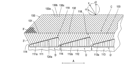
Figure 8 is a partial front view showing an embodiment of the display
apparatus of the invention. The display apparatus includes two or more display
devices, e.g., three display devices 111,112 and 113. The display devices 111,
112 and 113 have display areas 111 a, 112a and 113a, respectively. The display
areas 111a, 112a and 113a are separated from each other by boundary areas
114 (i.e., non-image areas). Connected to the separated display areas 111a,
112a and 113a, are introducing end faces D of optical fiber bundles 131,132 and
133, each of such bundles being for transmitting an image.
Each of the optical fiber bundles 131, 132 and 133 is formed in the
following manner. A plurality of optical fibers 3' are arranged side by side, so as
to form an optical fiber sheet 130 (shown in perspective). A plurality of optical
fiber sheets (e.g., 130a,130b,130c) are stacked and the optical fibers 3' in each
are then bent in the same direction toward a boundary area 114 at certain
A"'
...,. ~
portions 134a between the introducing end face D and an emitting end face C.
The adjacent side faces 118 on the emitting end face C side of two respective
adjacent optical fiber bundles, i.e., 131 and 132, and 132 and 133 are in contact
with each other and fixed with an adhesive or the like. The length of each optical
fiber 3' is determined by the width of the boundary area 114, the angle at whichthe optical fiber 3' is bent and the length of a straight portion of the optical fiber
3'. In view of the resulting display apparatus, it is preferable that the display
apparatus is as thin as possible, i.e., the optical fiber 3' is as short as possible.
Also, a preferred value of the diameter depends on the screen size and the
resolution of the composite display area. Preferably, the diameter of the optical
fiber 3' is set to be 250 ,um or less. The optical fiber bundles 131, 132 and 133
are formed in the same way and hence have the same construction.
Next, by way of an example, a method of fabricating the optical fiber
bundle 131 is described with reference to Figure 9. First, a plurality of optical
fibers 3' are arranged side by side and then cut to have a same prescribed
length, so as to form an optical fiber sheet 130. The optical fiber sheet 130 isbent at an angle 6~2 at a predetermined location 134a thereof, so as to form an
optical fiber sheet 130 having the bent portion at location 134a. A plurality ofoptical fiber sheets 130 are inserted and stacked adjacent to one another as
shown in Figure 9 in a groove 7a having a gradient bottom formed in a jig 7. At
this time, the gradient of the bottom of the groove 7a is an angle of ~2/2 with
respect to the angle 192. This is because the angle formed by the direction of the
diameter d of an optical fiber and the center of the bent portion 134a indicatedby a dot-chain line is half the bent angle ~2 formed by the portions of the optical
fiber sheet 130 on the sides of the introducing end face D and the emitting end
face C. Next, the stacked optical fiber sheets 130 are fixed together using a
resin or the like. The fixed optical fiber sheets 130 are then cut along the twodot-chain lines shown in Figure 9 to form the introducing end face D and the
emitting end face C, so as to complete the optical fiber bundle 131. The opticalfiber bundles 132 and 133 are also fabricated by the same way.
The bent angle ~2 iS selected such that when the introducing end faces
of the optical fiber bundles 131, 132 and 133 are connected to the corresponding
display areas 111a, 112a and 113a, the sides of the respective two adjacent
optical fiber bundles 131 and 132, and 132 and 133 are in contact with each
other. By selecting the bent angle appropriately, the edges of the emitting end
faces C of the optical fiber bundles 131,132 and 133 can be in contact with eachother irrespective of the spaces between the display areas 111 a,112a and 113a.
Therefore, according to the display apparatus of this embodiment, even
if the display areas 111 a, 112a and 113a of three display devices 111, 112 and
113 are separated from each other, a composite, continuous image can be
obtained by the optical fiber bundles 131, 132 and 133. In the display apparatushaving the above construction, the direction along the axis of each of the optical
fibers at the emitting end face C is oblique with respect to the display areas 111 a,
112a and 113a, whereby the display apparatus has a disadvantage that the
visual angle range is narrow. However, since there is a range of +X with respectto the center direction X in the diameter direction of the optical fiber, the viewing
angle range may not cause a problem depending on the position where the
display apparatus is set, or the direction which the display area of the displayapparatus faces.
The display apparatus to which the invention can be applied is not
limited to a display apparatus having three display devices, but the invention can
be applied to a display apparatus in which any number of display areas of display
devices are arranged in one direction.
The method of fabricating the optical fiber bundle 131 is not limited to
the above. Alternatively, straight optical fiber sheets are stacked in a group, and
then the stacked group of optical fiber sheets is bent as a whole so as to form
the optical fiber bundle 131. The structure of the optical fiber bundle 131 is also
not limited to the above. Alternatively, as is shown in Figure 10, spacers 64 may
be inserted between.the bent optical fiber sheets 130 and gaps between the
optical fiber sheets 130 and the spacers 64 may be filled with an adhesive 65.
When the spacers 64 are used, the thickness of the optical fiber bundle 131 can
be reduced, as is disclosed in Japanese Patent Application No. 3-293425.
Preferably, the spacers 64 are black in order to decrease the crosstalk from
adjacent optical fibers 3' and to enhance the black-mask effect.
- 13-
'
Figure 11 shows a display apparatus according to another embodiment
of the invention. The display apparatus of this embodiment includes two display
devices 114 juxtaposed in a direction A and two display devices 114 juxtaposed
in a direction B, i.e., four display devices 114, and an optical fiber bundle group
140 connected to the display devices 114. The display devices 114 have
respective display areas 114a. The optical fiber bundle group 140 is made up
of four optical fiber bundles 134. One end face D of each of the optical fiber
bundles 134 is connected to a corresponding display area 114a. Each of the
optical fiber bundles 134 has two outward facing slopes 134c on adjacent side
faces and two inward facing slopes 134d on the remaining side faces. The
optical fiber bundles 134 are joined at their side faces 134e in such a manner
that the outgoing slopes 134c face outside. In this way, the emitting end face Cof the optical fiber bundle group 140 connected to the display areas 114a of thefour display devices 114 serves as a plane of a composite display area.
Each of the optical fiber bundles 134 has a structure in which a
plurality of optical fiber sheets 231 shown in Figures 12 and 13 are stacked in a
direction A. Each optical fiber sheet 231 is obtained in the following manner. Aplurality of optical fibers 230 which are cut to have the same length are arranged
side by side in a direction B and bonded to be a sheet-like shape. Moreover, theoptical fiber sheet 231 is bent at a prescribed angle 6~3b in a direction B along a
portion (line) E, for example, positioned at approximately one-third the length
from the emitting end face C to the introducing end face D, as is shown in Figure
12. The optical fiber sheet 231 is also bent at a prescribed angle ~3a in a
direction A at the portion E, as is shown in Figure 13. Each of the optical fibers
230 has a core portion formed of acrylic as its center axis. Light which is
introduced into the optical fiber 230 from one end is emitted from the other end.
The values of the angles ~3a and ~3b are selected depending on the separation
between the adjacent display areas 114a, the position of the bent portion E, andthe like. The values of the angles ~93a and 193b may be the same value.
An exemplary fabrication method of the optical fiber sheet 231 is
described with reference to Figures 14A through 14E. First, as is shown in
Figure 14A, a plurality of long optical fibers 230a are arranged in parallel and
- 14-
then bonded with a water-soluble adhesive, so as to form a long optical fiber
sheet 231 a. Then, the long optical fiber sheet 231 a is cut into optical fiber sheets
231b each having a prescribed length, as is shown in Figure 14B. The optical
fiber sheet 231b is bent at an angle ~3b along the line E and in a direction along
a line across the surface of the optical sheet 231b, so as to form a bent optical
fiber sheet 231c, as is shown in Figure 14C.
Next, the bent optical fiber sheet 231c is dipped in a water. As a
result, the water-soluble adhesive is dissolved, and the bent optical fiber sheet
231c separates into a plurality of bent optical fibers 230c, as is shown in Figure
14D. The optical fibers 230c which are bent at the angle 193b are arranged within
a form 90. In the form 90 having a recessed portion, as is shown in Figure 14E,
both edges 91 of the recessed portion are bent at the angle 6~3b the same as theoptical fiber 230c. At the bottom of the recessed portion, a plurality of alignment
grooves 92 are formed for aligning the optical fibers 230c at a regular pitch. The
optical fibers 230c are arranged in the recessed portion of the form 90 and
bonded with a water-soluble adhesive. Thus, an optical fiber sheet 231e which
is bent at the angle ~3b in a direction parallel to the arranged direction of the
optical fibers 230c is obtained. As a last step, as is shown in Figure 14F, the
optical fiber sheet 231e is bent at the angle 6~3a along the line E across the
surface of the optical fiber sheet 231e, so as to obtain the optical fiber sheet 231.
According to the display apparatus of this example, a display area
having a size four times as large as that of the display area 114a of one of thedisplay devices 114 without seams can be obtained.
The number of display devices joined in one direction is not limited to
two. Alternatively, a display apparatus may have a structure in which three
display devices 114 are joined in each of the directions A and B, as is shown inFigure 15. In this display apparatus, nine optical fiber bundles, i.e., four optical
fiber bundles 134, four optical fiber bundles 135, and an optical fiber bundle 136
are joined to constitute an optical fiber bundle group 140. The emitting end face
C of the optical fiber bundle group 140 serves as a flat display area having a size
nine times as large as that of one of the display areas 114a. At the corners of
the optical fiber bundle group 140, the four optical fiber bundles 134 which are - 15-
~'
...~
bent in the two directions A and B as described above are provided. The four
optical fiber bundles 135 which are constituted by optical fiber sheets bent in one
direction are interposed between respective pairs of optical fiber bundles 134.
Each of the optical fiber bundle 135 has a pair of slopes (one is an outward
5 facing slope 135c and the other is not shown) on the opposing side faces. At the
center of the optical fiber bundle group 140, an optical fiber bundle 136 which is
square without bending is provided. The optical fiber bundles having the
outgoing slopes 134c, 135c, i.e., optical fiber bundles 134, 135 are disposed insuch a manner that the outgoing slopes 134c, 135c are directed outward.
In the display apparatus having the above-mentioned structure, a
display area having a size nine times as large as that of the display area 114a
of one display device 114 without seams can be obtained.
Figure 16 is a front view showing a display apparatus according to
another embodiment of the invention. This display device has the same structure
of the conventional display device shown in Figure 2 except for an optical fiberbundle 330. The same reference numerals are used for indicating elements
having the same structure as in the display device shown in Figure 2.
The display apparatus has two display devices 11 and 12. The display
devices 11 and 12 are juxtaposed in such a manner that display areas 11 a and
12a are oriented in the same direction. To the display areas 11a and 12a as
display input faces, the optical fiber bundle 330 for transmitting an image is
connected on the end face D. The optical fiber bundle 330 is obtained in the
following way. Optical fibers 331 are arranged side by side and bonded to each
other, so as to form an optical fiber sheet. The optical fiber sheets are stacked
into a shape of a block, which is the optical fiber bundle 330. Figure 16 shows
an end view of the optical fibers 331 in each of the optical fiber sheets. Figure
17 shows the arranged state of the optical fibers 331 in the optical fiber bundle
330. One end of the optical fiber bundle 330 is separated into two branch
portions 330a and 330b at a plane E so as to take the form of an inversed letterY. One portion 330a is connected to the display area 11 a such that it in inclined
at an angle e1 toward the display device 12. The other portion 330b of the
- 16-
,~
~L
3~
""~
optical fiber bundle 330 is connected to the display area 12a similarly inclinedtoward the display device 11 at the angle t~,.
The portions 330a and 330b of the optical fiber bundle 330 are bent
at the angle ~, at the plane E so as to be combined. The combined portion on
5 the end face C is oriented in a direction perpendicular to the display areas 11a
and 12a. At the end face C as an emitting end face of the optical fiber bundle
330, the optical fibers 331 are arranged at a regular pitch and have a convex and
concave relief (a waveform-like shape), so as to constitute a large display area.
The emitting end face C is described below in detail.
The two display devices 11 and 12 are driven through a driving circuit
(not shown) by split signals. The split signals are obtained by splitting an image
signal for each frame into two signals for right and left fields. Therefore, theimages appearing on the display areas 11a and 12a are displayed as an image
without discontinuity on the emitting end face C of the optical fiber bundle 330.
Therefore, a large-sized composite display area with high quality can be formed.A process for forming the convex and concave shape at the emitting
end face C of the optical fiber bundle 330 will now be described with reference
to Figures 18A through 18C. First, as is shown in Figure 18A, the optical fiber
bundle 330 having the same structure as that of the conventional optical fiber
bundle is formed. Then, as is shown in Figure 18B, a mold 332 having a convex
and concave surface which is mirror-finished is pressed against the emitting endface C of the optical fiber bundle 330 while heating. As a result, the optical fiber
sheets forming the optical fiber bundle 330 are bonded to each other and the
emitting end face C of the optical fiber bundle 330 takes the convex and concaveshape, as is shown in Figure 18C. The convex and concave of the mold 332 is
formed at the same pitch as that of the center axes of the adjacent optical fibers
331 in the optical fiber bundle 330. Accordingly, the emitting end face C of each
of the optical fiber sheets constituting the optical fiber bundle 330 takes a shape
that the center portion in a thickness direction of the optical fiber sheet (in a
direction A in Figure 16) is convex, and the edge portions are recessed.
In this embodiment, the pitch of the convex and concave is the same
as that of the arranged pitch of the optical fibers 331, but alternatively, the pitch
A
can be set to be smaller. Since the surface of the mold 332 is mirror-finished,
the surface roughness of the convex and concave shape is very low. Therefore,
it is possible to prevent the occurrence of light scattering on the end face C.
In the forming process shown in Figures 18A through 18C, the convex
and concave of the end face C of the optical fiber bundle 330 are successively
formed in a thickness direction of the optical fiber bundle 330, i.e., the direction
A in which the optical fiber sheets are stacked, as is shown in Figure 19A. In this
case, the visual angle range is wide in the thickness direction A of the opticalfiber bundle 330. In another case, as is shown in Figure 19B, the convex and
concave of the end face C are successively formed in a widthwise direction B of
the optical fiber bundle 330. In this case, the visual angle range is wide in the
widthwise direction B. In other words, the convex and concave of the end face
C can be successively formed in a direction in which the visual angle range is
desired to be wide. Alternatively, it is effective to successively form the convex
and concave in two directions different from each other.
The viewing angle can be enlarged by forming the fine convex and
concave shape at the emitting end face C of the optical fiber bundle 330. For
example, the viewing angle can be enlarged by methods shown in Figures 20A
through 20D. First, as is shown in Figure 20A, a transparent thin sheet 333a is
pressed using the mold 332 while heating. To the surface of the pressed thin
sheet 33a, the convex and concave shape is transferred, and a thin sheet 333
having a surface with convex and concave is obtained, as is shown in Figure
20C. The thin sheet 333 with convex and concave is stuck on the end face C of
the optical fiber bundle 330, as is shown in Figure 20D. Alternatively, as is
shown in Figure 20B, a roller 334 having a surface with the convex and concave
shape may be used.
The present invention is not limited to the above-described example,
but can be applied to various types of display apparatus including an optical fiber
bundle. In such a case, the emitting end face of the optical fiber bundle shouldbe made into a convex and concave shape. For example, the invention can be
applied to a display apparatus shown in Figure 21. The display apparatus
includes two display devices 21 and 22, and an optical fiber bundle 335. The
- 18-
A
display devices 21 and 22 have display areas 21a and 22a, respectively. The
display areas 21a and 22a are connected to an introducing end face D of the
optical fiber bundle 335. The optical fiber bundle 335 is bent at an angle ~4 ata plane E between the emitting end face C and the introducing end face D, and
separated into two portions. The portions are then bent at the same angle ~4 at
a plane F between the plane E and the introducing end face D in respective
directions reversed to the bent directions at the plane E.
The preser~t invention is not limited to the optical fiber bundle having
optical fibers 331 arranged vertically and horizontally, as is shown in Figure 17.
Alternatively, the present invention can be applied to an optical fiber bundle
having optical fibers 331 arranged in an obliquely adjacent manner which is
shown in Figure 22, or to an optical fiber bundle in which a plurality of optical
fibers only having core portions are bundled with an adhesive having a lower
refractive index than that of the core portions.
A method of treating an end face of an optical fiber used in a display
apparatus or the like for performing a large-area display by transmitting an image
through an optical fiber bundle will now be described. Figures 23A through 23E
are sectional views showing a process for treating the end face of an optical fiber
bundle according to the invention.
First, as is shown in Figure 23A, on one end face of an optical fiber
bundle 50, a photosensitive resin 52 such as an optically dimerization type resin
mainly including polyvinyl cinnamate is applied. The optical fiber bundle 50 is
obtained by fastening a plurality of optical fibers 51 side by side. Each of theoptical fibers 51 has a core portion 51a and a clad portion 51b.
Then, as is shown in Figure 23B, the other end face of the optical fiber
bundle 50 on which the photosensitive resin 52 is not applied is irradiated withlight for exposure. The exposure light passes through the core portion 51a and
exits from the end face on which the photosensitive resin 52 is applied. The
emitted light has a certain intensity distribution. As a result, as is shown in
Figure 23C, only the photosensitive resin 52 which is applied over the core
portions 51a is exposed and partially cured, so as to form cure portions 53. On
the other hand, since the clad portions 51 b do not transmit light therethrough, the
- 19-
A
~ ~ ~ 4 ~ ~ 3
.,,"..
photosensitive resin 52 over the clad portions 51b is not exposed to light, so as
to be an uncured portion 52a.
Then, the partially cured photosensitive resin 52 is developed using a
developer such as trichlene, so as to remove the uncured portion 52a which is
5 not exposed. At this step, the boundary between the cured portion 53 and the
uncured portion 52a is not clearly defined, so that part of the uncured portion 52a
around the cured portion 53 is not completely removed, as is shown in Figure
23D. The photosensitive resin 52 is thus developed to take a shape of
successive lenses having gentle curves.
Finally, as is shown in Figure 23E, the optical fiber bundle 50 is
exposed to light on the end on which the photosensitive resin 52 was applied, soas to completely cure the remaining uncured portion 52a. Thus, a lens array 54
is obtained.
Figure 24 shows a relationship between the amount of exposure light
and the cured degree of the photosensitive resin 52 used in this embodiment.
It is seen from Figure 24 that the cure of the photosensitive resin 52 progresses
quickly after reaching a certain amount of exposure light. Accordingly, a
difference between the cured portion 53 and the uncured portion 52a is clearly
observed, so that this method is suitable for forming the lens-like shape.
The lens array 54 formed on the end face of the optical fiber bundle
50 by the above method has a successively curved surface and is formed
integrally with the optical fiber bundle 50. Accordingly, even if the arrangement
of the optical fibers 51 in the optical fiber bundle 50 is irregular, the lens array 54
can readily be applied. As a result, it is unnecessary to measure the pitch of the
arranged optical fibers 51 and to provide a mask for the formation of the lens
array, and a process step for connecting the optical fiber bundle 50 with the lens
array is not required, such that the production cost can be reduced. Moreover,
it is unnecessary to align the optical fibers 51 with the lens array, as in the prior
art method.
~n embodiment of an optical fiber bundle used in a display apparatus
which performs a large-area display by transmitting an image through the opticalfiber bundle will now be described.
- 20 -
Figure 25 is a sectional view showing an optical fiber bundle 60
according to the invention. The optical fiber bundle 60 is obtained by the
following manner. Optical fibers 61 are arranged side by side and bonded to
each other, so as to form an optical fiber sheet. The optical fiber sheets are
5 stacked to take the shape of a block. Each of the optical fibers 61 has only acore portion 61a. In the optical fiber bundle 60, the adjacent optical fibers 61 are
in contact with each other. A gap between the adjacent optical fibers 61 is filled
with an adhesive 62 having a refractive index slightly lower than that of the core
portion 61 a, so that the optical fibers 61 are fixed to each other. The value of the
10 refractive index of a n~aterial as the adhesive 62 is preferably lower than that of
the core portion 61a by a value of 0.1 to 0.01. Specifically, when the core portion
61a is formed, for example, of a polyurethane plastic, polymethyl methacrylate
(PMMA) or the like is suitably used as the material of the adhesive 62.
As described above, the optical fiber bundle 60 is formed by optical
fibers 61 having only core portions 61a and the adhesive 62 having a lower
refractive index than that of the core portions 61a. Thus, the adhesive 62 can
serve as a conventional clad portion. Therefore, the optical fiber bundle 60 does
not necessitate the clad portion, so that the occupied ratio of the core portions
61a can be increased. The occupied ratio of the core portions 61a in the opticalfiber bundle 60 is represented by the area occupied by the core portions 61a perunit area in cross section of the bundle 60, and is referred to as the filling factor.
In a conventional case of an optical fiber having an outer diameter of 250,um and
a core diameter of 240,um, the filling factor is 72.4%. In this example in whichthe outer diameter of the optical fiber 61 is 250 ,um, the filling factor is 78.5%,
which is higher than in the conventional case.
The present invention is not limited to this example, but alternatively,
the optical fiber bundle 60 having the above structure can be applied to varioustypes of display apparatus, for example, to an optical fiber bundle having optical
fibers 331 arranged in an obliquely adjacent manner, as is shown in Figure 22.
A method of fabricating an optical fiber bundle employed in a display
apparatus or the like for providing a large-area display by transmitting an image
through the optical fiber bundle will now be described. Figures 26A through 26F
- 21 -
are sectional views showing respective process steps of the method of fabricating
the optical fiber bundle according to this embodiment.
First, an upper guide plate 71 is superimposed on a lower guide plate
72. A plurality of holes 73 are formed at a regular pitch in both the upper guide
plate 71 and the lower guide plate 72. As is shown in Figure 26A, optical fibers81 are disposed through the holes 73. Then, in order to maintain the
perpendicular relationship between the upper and lower guide plates 71 and 72
and the optical fibers 81, as is shown in Figure 26B, a wax 74 is applied to thelower face of the lower guide plate 72. Then, the upper guide plate 71 is
upwardly moved by 20-50 mm. In this state, in order to fix the optical fibers 81to each other, adhesives 75a and 75b are applied to the lower surface of the
upper guide plate 71 and the upper surface of the lower guide plate 72, as is
shown in Figure 26C after a release agent (not shown) is applied to the lower
surface of the upper guide plate 71 and the upper surface of the lower guide
plate 72.
Next, the upper guide plate 71 is shifted in a desired direction with
respect to the lower guide plate 72, so that the optical fibers 81 are bent at adesired angle. The optical fibers 81 between the upper guide plate 71 and the
lower guide plate 72 are fixed to each other with an adhesive 75c, as is shown
in Figure 26D. Thereafter, as is shown in Figure 26E, the wax 74 is dissolved
by a solvent, and the upper and the lower guide plates 71 and 72 are removed.
Finally, as is shown in Figure 26F, the surface is finished by cutting the
adhesives 75a and 75b slightly.
According to the fabricating method, when the optical fibers 81 are
bent, the optical fibers 81 are fixed by the holes 73 formed at a regular pitch in
the upper and the lower guide plates 71 and 72. As a result, the optical fiber
bundle which is an integer of the optical fibers 81 has a regular arrangement.
The bending angle applied to the optical fiber bundle can readily be controlled by
adjusting the shift width of the upper guide plate 71 in a desired direction with
respect to the lower guide plate 72.
If the employed optical fibers 81 have only core portions, the structure
of the optical fiber bundle can be the same as in the fifth example. In this case,
- 22 -
the adhesive 75c serves as the clad portion for the optical fibers 81, so that the
light transmissivity can be improved.
Figures 27 and 28 show a display apparatus according to another
embodiment of the present invention. Figure 27 is a front view and Figure 28 is
5 a perspective view. The display apparatus includes two display devices 411
juxtaposed in a direction A and two display devices 411 juxtaposed in a direction
B, i.e., a total of four display devices 411, and an optical fiber bundle group 440
connected to the display devices 411 via a film for preventing moisture
permeation (not shown; hereinafter, referred to as an "anti-moisture permeation
film"). Each of the display devices 411 has a display area 411a. The optical
fiber group 440 is constituted by four optical fiber bundles 434. A sealing
member 470 is formed so as to cover the portion where the display areas 411 a
are coupled to the optical fiber bundles 434. Each optical fiber bundle 434 has
two outgoing slopes 434c on adjacent side faces. Four optical fiber bundles 434
are connected by side faces 434d in such a manner that the outgoing slopes
434c are directed to the outside. On an emitting end face C of the optical fiberbundle group 440, an anti-moisture permeation film 460 is formed. The anti-
moisture permeation film formed between the display areas 411a and the optical
fiber bundles 434 and the anti-moisture permeation film 460 on the emitting end
face C are made, for example, from a coating agent such as a synthetic resin of
a vinylidene chloride system or a film having an anti-moisture permeation effect.
Thus, the emitting end face C of the optical fiber bundle group 440 constituted
by the four display devices 411 is made to form a plane, whereby a composite
display area can be formed.
The opticai fiber bundle 434 has the same structure as that of the
optical fiber bundle 134 of the display apparatus shown in Figure 11. That is, the
optical fiber bundle 434 is constituted by a plurality of optical fibers which are cut
to have a prescribed length. The core portion of the optical fiber is formed of
acrylic.
The anti-moisture permeation film provided between the display areas
411a and the optical fiber bundles 434, and the anti-moisture permeation film onthe emitting end face C can be formed by the following various methods.
- 23 -
A first method is described with reference to Figures 29A through 29E.
First, as is shown in Figure 29A, gaps between adjacent optical fibers 435 in the
vicinity of both end faces C and D of an optical fiber bundle 434 are sufficiently
filled with an adhesive resin 461 of a certain thickness having an anti-moisturepermeation effect. The resin 461 is, for example, a transparent epoxy resin. At
this time, as required, the end faces C and D of the optical fiber bundle 434 are
cut so that they are made even. Then, as is shown in Figure 29B, after the resin461 is sufficiently cured, the cured resin 461 is cut, so as to form a very thintransparent resin layer 462 on each of the end faces C and D. In a case where
the end face of the optical fiber bundle 434 is directly cut, since the end face C
or D thereof includes different materials having different cut resistances such as
acrylic (the optical fibers), an epoxy resin (the filling adhesive member), and
polyester or the like (the spacers), the cutting edge of a cutter is vibrated due to
the different cut resistances, whereby it is difficult to obtain a good worked
surface. On the other hand, in this first method, since the cut resistance is
constant, a good worked surface can be obtained. Thereafter, as is shown in
Figure 29C, on the transparent resin layer 462 formed on the emitting end face
C, a photosensitive polymer (hereinafter, referred to as a 2P resin) 463 is applied.
As the 2P resin 463, for example, a 2P resin available from HOYA Inc. (refractive
index: 1.52, saturated water absorption: 0.68%) is used. Regarding the saturatedwater absorption, the saturated water absorption of the 2P resin 463 is one-third
of that of PMMA (saturated water absorption: 2.2%) as a material of the core
portion of each optical fiber 435, which is preferable. A lower saturated water
absorption of the 2P resin is more preferable. Next, as is shown in Figure 29D,
the upper surface of the 2P resin 463 is pressed using a transparent substrate
436 on which a mold release agent is applied, so as to make the surface of the
2P resin 463 flat. Thus, the thickness of the 2P resin 463 is adjusted. Since the
2P resin 463 acquires the flatness of the surface of the transparent substrate
436, it is not necessary to finish the surface of the 2P resin 463 to a mirror face
after removing the transparent substrate 436. Ultraviolet light 437 is then
projected onto the emitting end face C from the outside of the transparent
substrate 436, so as to cure the 2P resin 463. Finally, as is shown in Figure
- 24 -
A
29E, the transparent substrate 436 is removed, so that the anti-moisture
permeation film 460 which has a mirror surface is obtained. At the end face D,
the very thin transparent resin layer 462 is finished to be a mirror face.
A second method is described with reference to Figures 29A,29B,30A
5 and 30B. First, as is shown in Figure 29A, gaps between the adjacent optical
fibers 435 in the vicinity of the end faces C and D of the optical fiber 434 aresuffficiently filled with an adhesive resin 461 of a certain thickness having an anti-
moisture permeation effect. The resin 461 is, for example, a transparent epoxy
resin. Also, as required, the end faces C and D of the optical fiber bundle 434
are cut. Then, as is shown in Figure 29B, after the resin 461 is cured, the resin
461 is cut to form a very thin resin layer 462. Then, as is shown in Figure 30A,the transparent resin layer 462 formed on the emitting end face C is coated witha resin 464 (e.g., a transparent epoxy resin) having an anti-moisture permeationeffect. After the transparent resin 464 is cured, the end face C is cut and finished
to a mirror face, as is shown in Figure 30B. At the end face D, the transparent
resin layer 462 which has been cut is finished to a mirror face.
In the first and second methods, when the optical fiber bundle 434 has
a structure using the spacers 64 shown in Figure 10, only the spacers 64 are
black, and a transparent resin is used for filling the gaps between the optical
fibers 130 and the spacers 64. The transparent resin is, for example, an epoxy
resin 2023 (saturated water absorption: 0.65%) available from THREE BOND Inc.
In a third method, first, both the emitting end face C and the
introducing end face D of the optical fiber bundle 434 are cut, and then 2P resins
are applied on both the end faces C and D. Then, each outer surface of the 2P
resin is pressed using a transparent substrate on which a mold release agent is
applied, so as to make the surface of the 2P resin into a plane, whereby the
thickness of the 2P resin is adjusted. Thereafter, ultraviolet light is projected onto
both the end faces C and D from the outside of the transparent substrate, so as
to cure the 2P resins. Finally, the transparent substrates are removed, so that
the anti-moisture permeation films 460 having mirror surfaces are obtained on
both the end faces C and D. As the 2P resin, for example, the above-mentioned
2P resin available from HOYA Inc. is preferably used.
- 25 -
,"~ "
~.
~ g~
In a fourth method, both the emitting end face C and the introducing
end face D of the optical fiber bundle 434 are cut, and then both end faces C and
D are coated with an epoxy resin. Next, after the epoxy resin is cured, both endfaces C and D are cut again so as to be mirror faces. In this case, since the cut
resistance does not fluctuate, a good worked surface can be obtained, as in the
above-described methods.
In a fifth method, anti-moisture permeation films formed on the end
faces C and D of the optical fiber bundle 434 by any one of the above four
methods are coated with a resin of vinylidene chloride system. As the vinylidenechloride resin, for example, SaranlatexTM, available from ASAHIKASEI, and
ChretronlatexTM, available from KUREHA KAGAKU, may be used. By this
method, the prevention of water absorption by the anti-moisture permeation film
460 or the like can be further improved.
As described above, in a display apparatus in which anti-moisture
permeation films 460 or the like are formed on both the end faces C and D of theoptical fiber bundle 434, even if the core portion of each optical fiber is made of
acrylic, the core portion will not absorb the moisture from the air. As a result, the
optical fiber does not expand and shrink repeatedly owing to the absorption of
moisture from the air. Therefore, no cracking occurs at the end faces of the
optical fiber bundle group 440, which prevents image distortion. Moreover, if the
anti-moisture permeation film 460 is finished to a mirror surface, light scattering
due to the unevenness of the emitting end face C can be prevented, whereby a
vivid image can be provided.
In the display apparatus according to this embodiment, the sealing
member 470 is formed so as to cover the portion where the display areas 411a
and the optical fiber bundles 434 are coupled (Figure 28). Because of this
sealing member 470, small gaps are sealed, so that fine dirt or moisture is
prevented from entering. Therefore, the occurrence of the above-mentioned
faulty picture elements can be eliminated. As the sealing member 470, a usual
sealing member may be used as far as the sealing member has a good sealing
ability and the material thereof is difficult to change. If the sealing member 470
maintains elasticity for a long period, it will have resistance against vibration or
shock to some extent and will continue to adhere, such that gaps are not likely
to occur. It is necessary to inject the sealing member 470 over the portion where
the display areas 411a and the optical fiber bundles 434 are coupled, using a
sealing member injecting nozzle or the like. It is desired that the sealing member
5 injecting nozzle has a sufficiently tapered end and an appropriate length, since
the gap 56 formed by a facing pair of ingoing slopes 434d of the optical fiber
bundles 434 is narrow.
~A.