Note: Descriptions are shown in the official language in which they were submitted.
~u.w ~..'t 17977
PC:T/US92/~26~~
REMOTELY CONTROLLED APPARATUS FOR CONDTTIOI~TIdG TELEPHONE
LINE EXCLUSIVE OF METALLTC DC BYPASS PAIR
FIELD OF THE INVENTION
The present invention relates in general to
telecommunications systems and is particularly directed
to an apparatus, installed in a remote terminal, for
conditioning a telephone line pair under the control of
a direct access test unit located in the central office,
and exclusive of the use of a metallic DC bypass pair
normally provided for the purpose.
BACKGROUND OF THE INVENTION
The proliferation of carrier system service
throughout the telecommunications industry has mandated
the need for testing and conditioning an ever increasing
number of telephone liners of digital loop carrier or pair
gain systems. Traditionally, such testing has been
carried out by means of a metallic DC bypass pair, which
extends from the central office terminal to the remote
terminal where access to the telephone lines of interest
is provided. Equipment installed at the central office
transmits test condition signals over the DC bypass pair
to the remote terminal and subsequently to the line uncl~r
test (LUT).
Unfortunately, this test and conditioniaig scheme
suffers from a number of shortcomings including the fact
that, in may cases, the test results represent not only
conditions and faults on the line (loop) being tested,
but else those of the DC bypass pair, which is connected
in series with the LUT. Consequently, fault conditions
such as noise, crosstalk, unacceptable voltage levels,
etc. on the DC bypass pair manifest themselves by way of
inaccurate results in the course of evaluating the LUT.
~V~ 92/17977 P~'T/US92/02r.,.-,;'
~~~ ~'~~~~t9
2
Another problem is the fact that such test systems
suffer from an inherent functional limit of approximately
2800 ohms (roughly ten miles of copper wire), beyond
Which point line testing is generally considered to be
unreliable. Thus, the effective reach of a conventional
telephone line test system is limited by the distance
between the central office and the remote terminal.
Indeed, in many instances this distance is so great as to
preclude the use of a centralized test system which
utilizes the DC bypass metallic pair for loop carrier
applications. Moreover, with the advent and proliferation
of optical fiber as a communication link for voice and
data traffic between the central office and the remote
terminal, it. can be seen that the ability to use a
metallic bypass pair for test purposes is becoming more
limited. In some cases metallic bypass pairs are not even
included with fiber optic installations, making the use
of a conventional centralized test system virtually
impossible.
SUMMARY OF THE INVENTION
In accordance with the present invention, the above-
described problems of conventional centralized test
systems are effectively obviated by a remotely controlled
line conditioning apparatus that is installed in the
terminal where access to the telephone loop to be tested
is readily available. Although ,a metallic bypass pair
from 'the central office to the (remote) terminal may else
be available, its presence and/ar condition does not
affect the ability of the apparatus to condition the LUT.
To this end, the telephone line conditioning
apparatus of the present invention includes a telephone
line termination unit and an intelligent control unit.
The telephone line termination unit has a telephone line
access port to which a telephone line pair is selectively
coupled, and is operative to controllably impart a
selected one of a plurality of electrical signalling
CA 02084308 2001-12-20
3
conditions to the telephone line pair under test. The
control unit has a communication modem through which
communication signals containing telephone line
conditioning messages are coupled to a channel unit in
the remote terminal, the channel unit being coupled with
the central office/remote terminal communication link.
The control unit also includes a micro-controller, which
is coupled to the modem, for generating telephone line
unit control signals in response to line conditioning
messages from a host unit located at the central office.
Preferably, the central office-resident host system is a
direct access test unit of the type described in U.S.
Patent No.4,841,560, assigned to the assignee of the
present applicatiorm Control sinal.s generated by the_.micro-
controller control the operation of the telephone line
termination unit Which conditions the telephone line
pair.
The telephone line termination unit preferably
comprises a telephone line condition selection circuit
which contains a plurality of switching devices (relays)
coupled to receive respectively different telephone line
condition-representative inputs. The relays are
selectively controlled by control signals from the
control processor to impart a selected telephone line
condition to a respective telephone line pair. The
selected telephone line condition may involve the
application of prescribed voltages to the telephone line
pair, or the application of predetermined tone signals to
either or both lines of said telephone line pair. It may
also include shorting the telephone line pair together,
shorting either or both sides of the line to ground
potential, opening the telephone line pair, and the
monitoring of the telephone line pair for the presence of
voice or data activity.
CA 02084308 2002-08-28
4
Because of its intelligent control functionality and
its ability to exchange line conditioning messages with
the host system, the telephone line conditioning
apparatus of the present invention has the ability to
perform a variety of software-driven operations. For
example, the telephone line conditioning apparatus of the
present invention may be equipped with the ability to
perform a line conditioning function as specified by the
host system for an extended period of time., as determined
by the user of the host equipment. In such a case, after
the connection between the host and the remote terminal
has been released, the apparatus of the present invention
may perform specified conditioning of the line pair and
make its modem access port available for further messages
from the host. While maintaining the specified line
conditioning function, the invention may be accessed by
the host and may permit any line conditioning function to
be performed including cancellation of the particular
function being maintained. In addition, each time a line
conditioning function is invoked, a verification test may
be carried out in order to assess the apparatus' current
capacity to provide the specified conditioning function.
In a first aspect, the present invention provides for
use with a telephone system including a
central office which communicates with a remote terminal
by way of a central office/remote terminal communication
link, the remote terminal being coupled to respective
telephone lines through which user telephone devices have
access to the telephone system, an apparatus for
conditioning a respective telephone line by way of a
telephone line conditioning control unit at the central
office comprising:
CA 02084308 2002-08-28
4A
a telephone line termination unit having a telephone
line access port to which a telephone line pair may be
coupled, said telephone line termination unit including
means for controllably imparting a selected one of a
plurality of electrical signalling conditions by way of
said telephone line access port to a telephone line pair
coupled thereto; and
a control unit, coupled to said telephone line
termination unit and said central office/remote terminal
communication link, for receiving telephone line
conditioning messages from said central office and
controlling the operation of said telephone line
termination unit. -
In a second aspect, the present invention provides for
use with a telephone system including a
central office which communicates with a remote terminal
by way of a.central office/remote terminal communication
link, the remote terminal being coupled to telephone line
pairs through which user telephone devices have access to
the telephone system, an apparatus, provided at said
remote terminal, for enabling a selected one of said
telephone line pairs to be conditioned from said central
office comprising:
a telephone line termination unit having a telephone
line access port to which a telephone line pair may be
selectively coupled, said telephone line termination unit
including means for controllably imparting a selected one
of a plurality of electrical signalling conditions by way
of said telephone line access port to a telephone line
pair coupled thereto; and
CA 02084308 2002-08-28
4B
a control unit having a communication port coupled
to said central office/remote terminal communication link
for receiving a telephone line conditioning message from
said central office, and a control link coupled to said
telephone line termination unit for supplying telephone
line unit control signals for controlling the operation
of said telephone line termination unit and thereby the
conditioning of said telephone line pair, in accordance
with the contents of a telephone link conditioning
message from said central office.
In a third aspect, the present invention provides for
use with a telephone system including a
central office which communicates with a remote terminal
by way of a central office/remote terminal communication
link, the remote terminal being coupled to telephone line
pairs through which user telephone devices have access to
the telephone system, a method for enabling a selected
one of said telephone line pairs to be conditioned from
said central office comprising the steps of:
(a) installing in said remote terminal a telephone
line conditioning apparatus, which includes a telephone
line termination unit having a telephone line access port
to which a telephone line pair may be selectively
coupled, and being operative to controllably impart a
selected one of a plurality of electrical signalling
conditions by way of said telephone line access port to
a telephone line pair coupled thereto, and a control unit
having a communication port coupled to said central
office/remote terminal communication link for receiving
CA 02084308 2002-08-28
4C
a telephone line conditioning message from said central
office, and a control link coupled to said telephone line
termination unit for supplying telephone line unit
control signals for controlling the operation of said
telephone line termination unit and, thereby the
conditioning of said telephone line pair, in accordance
with the contents of a telephone line conditioning
message from said central office; and
(b) transmitting a telephone line conditioning
message from said central office by way of said central
office/remote terminal communication link to said control
unit, in response to which message said control unit
outputs telephone line unit control signals for
controlling the operation of said telephone line
termination unit and thereby the conditioning of said
telephone line pair.
BRIEF DESCRIPTION OF THE DRAWINGS
Figure 1 diagrammatically illustrates a simplified
example of a representative carrier telephone network
with which the remotely controlled telephone line
conditioning apparatus of the present invention is
intended to be used:
Figure 2 diagrammatically shows the general
configuration of the telephone line termination apparatus
of the present invention;
Figure 3 schematically illustrates the circuitry of
the modem, ring detect, off-hook interface between the
line conditioning apparatus and a channel unit in the
remote terminal; and
V'"~ 92!17977 PCT/U592/02fi88
Figures 4 and 5, taken together, form a schematic
illustration of line condition relay circuitry to which
the line under test and a channel unit are ported.
DETAIT,~ED DESCRIPTION
Before describing in detail the remotely controlled
line conditioning apparatus in accordance with the
present invention, it should be observed that the present
invention resides primarily in a novel- structural
combination of conventional telecommunication cixcuits
and components and not in the particular detailed
configurations thereof. Accordingly, the structure,
control and arrangement of these conventional circuits
and components have been illustrated in the drawings by
readily understandable block diagrams which show only
those specific details that are pertinent to the present
invention, so as not to obscure the disclosure with
structural details which will be readily apparent to
those skilled in the art having the benefit of the
description herein. Thus, the block diagram illustrations
of the Figures do not necessarily represent the
mechanical structural arrangement of the exemplary
system, but are primarily intended to illustrate the
major structural components o~ the system in a convenient
functional grouping, whereby the present invention may be
more readily understood.
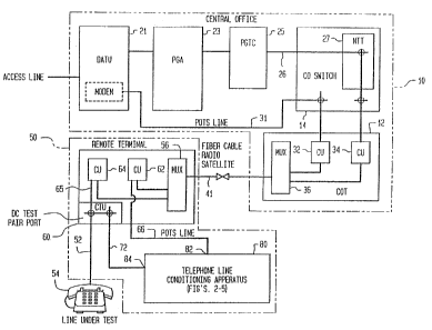
Figure 1 diagrammatically illustrates a simplified
example of a representative carrier telephone network
with which the remotely controlled telephone line
conditioning apparatus of the present invention is
intended to be used. The netw~rk itself is shown as
comprising a central office 1~, which contains a central
office terminal 12 and an associated central office
switch 14. The central office may also include a direct
access test unit 2l, a pair gain applic~ue 23 and a pair
gain test controller 25, which are coupled via link 26 to
a no test trunk 27 within the central office switch 14.
w0 ~2~7797' PCT/L1892/026F~'~ '~
6
As pointed out previously, direct access test unit or
DATU 21 within the central office-resident host system
preferably comprises a direct access test unit of the
type described in U.S. Patent No.4,841,560, assigned to
the assignee of the present application and the
disclosure of which is herein incorporated. DATU 21 may
be coupled through central office switch 14 by way of a
conventional PATS ( plain old telephone system) link
(e. g, copper wire) 31 to a channel unit 32 within central
office terminal 12. Teraninal 12 is also shown as
including a channel unit 34. Each of channel uni~ts-32 and
34 is coupled by way of a multiplexer 36 to a central
office/remote terminal link 41. Link 41 is not limited to
any particular type of communication medium and may
comprise, for example, conventional copper wire, a
satellite link, radio link, or fiber optic cable.
The telephone network of Figure 1 further includes
a remote terminal 50, which is coupled to a plurality of
telephone lines 52 through which user telephone devices
54 have access to the telephone system. Like central
office terminal 12, remote terminal 50 contains a
multiplexer 56 coupled to central office/remote terminal
communication link- 41 and associated channel units 62,
64. As will be described in greater detail with reference
to Figures 4 and 5, channel unit 64 is coupled to a
multiport connection interface 60. This interface
provides tip and ring connections to a line under test
52, and to t'ip and ring connections of test pair link 72.
Channel unit 62 is coupled to a POTS line 66. POTS line
66 arid DC test pair 72 are coupled to respective
communication and line conditioning parts 82 and 84 of a
telephone line conditioning ap~aratus,80 of the present
invention (ta be described more fully below with
reference to Figures 2-5).
w "'192/ l 7977 f CT/ 0592/02688
As pointed out briefly above, telephone line
conditioning apparatus a0 operates in response to
conditioning control messages forwarded to it from the
DATU 21 at central office ZO to controllably condition a
telephone line pair (e.g. line pair 54) exclusive of the
use of a metallic DC bypass pair normally provided for
the purpose. Such a normally provided DC bypass pair is
not shown in Figure 1 in order to underscore the
communication and control mechanism through which the
present invention operates to perform remote terminal
conditioning of an associated line pair. Namely, although
a metallic bypass pair from the central office to the
(remote) terminal may be available, the presence and/or
condition of such a metallic bypass pair does not affect
the ability of the apparatus to condition the line under
test.
The telephone line conditioning apparatus of the
present invention is diagrammatically shown in Figure 2
as comprising a telephone line termination unit 100 and
an intelligent control unit 110. Telephone line
termination unit 100 has a telephone line access port 102
to which a telephone line test pair (e.g. test pair 72)
is selectively coupled, and, as will be described in
detail below with reference to Figures 4 and 5, is
operative to controllably. impart a selected one of a
plurality of electrical signalling conditions to the
telephone line pair 72 under test. Control unit 110
includes a communication modem 112 through which
communication signals containing telephone line
conditioning messages are coupled via link 66 to the
remote terminal channel unit 62 which, in turn, is
coupled by way of multiplexer 56 with central
office/remote terminal communication link 41. Control
unit 110 also includes a microacontroller 120, which is
comprised of a microprocessor 122, attendant memory 124,
and is coupled with associated. power supply and reset
circuitry 126, and an intro control unit bus 116 to modem
iV~O Q2:17977 F'C'f/U~92/02bg"...~,
t~~~~~~~,v
112. As trill be explained more fully below, in response
to line conditioning messages from the host unit (DATU)
located at the central office, micro-controller 120
generates telephone line termination unit control signals
for controlling the operatian of the telephone line
termination unit which conditions the telephone line
pair. Micro-controller 120 is driven by supervisory
monitor and control software in memory 124. Rather than
detail the application program, a code listing of which
is not necessary for an understanding of the present
invention, the manner in which the control program
controls the operation of the line conditioning
apparatus, in particular, line termination unit 100, will
be described below in terms. of actually monitored node
activity states and control signals that are asserted by
the micro-controller in response to those states.
Telephone linewtermination unit 100 contains a
plurality of switching devices (relays) and associated
input/output driver circuits which are coupled to receive
respectively different telephone line condition-
reprpsentative inputs, and are controlled by control
signals from micro-controller 120, in order to impart a
selected telephone line condition to the telephone line
pair under test. The selected telephone line condition
may involve a variety of actions, including but not
limited to the application of prescribed voltages to the
telephone line pair, the application of predetermined
tone signals to either or both lines of the telephone
line pair, shorting the telephone line pair together,
shorting either or both sides of the line 'to ground
potential, opening the telephone line pair, and the
monitoring of the telephone line pair for the presence of
voice or data activity.
e~w g2«~r~~~ ~criu~~zio2~sg
.;
Figure 3 schematically illustrates the manner in
which modem 112 is interfaced with a link 66, including
the detection of ringing signal from channel unit 62 in
the remote terminal, and providing modem coupling to link
6s in response to detecting an off-hook state from the
modem. For. incoming calls, a ring detector 130 includes
an electro optic coupler unit 132 comprised of a light
emitting diode coupled across the Tip 133 and Ring 134
portions of link 66 and a phototransistor 136, the
collector and emitter. of which. are coupled to a ring
detect OR gate 138. The output of gate 138 is coupled to
a ' Ring' input of modem 112 . The presence of a ringing
signal on link 66 causes the emitter voltage of
phototransistor 36 to go low, whereby OR gate 138
supplies a low, Ring Detect output to modem 112.
For outgoing calls, an Off-Hook detector is
comprised of driver transistor 142, the lease 143 of which
is coupled to an output 'off hook (OH)' port 119 of modem
112 and the collector 145 output of which is coupled to
the winding of relay 144. Relay 144 has a first set of
contacts 146 coupled in circuit with an LED indicator 147
and a second set of contacts coupled in circuit with
first and second primary coils 151, 152 o~f a coupling
transformer 150. The secondary coil 154 of coupling
transformer 15b is coupled to respective tip and ring
ports of modem 112. When modem 112 forces off hook output
119 low, transistor l42 is turned on, thereby energizing
relay 144 and providing a transformer coupling of the tip
and ring leads of link 66 through the series-connected
primary coils 151 and 152. :also included in the modem'-to-
telephone link interface are a Zener diode bridge 16.0
which serves to clamp perturbations at the tip and ring
parts of the modem, and reverse-parallel connected Zener
diodes across Tip and Ring for overvoltage protection.
wo ~z~~7977 Pc~~°ru~~zro~bs~~~~
to
Figures 4 and 5, taken together, form a schematic
illustration of the arrangement of and interconnection of
a plurality of switching devices (relays) resident within
telephone line termination unit 100, and which operate in
response to control signals from micro-controller 120 for
imparting a selected telephone line condition to the
telephone line pair under test. The multiport connection
interface 60 of Figure 1 is shown in detail as including
respective tip and ring ports 161 and 162 coupled to the
tip and ring portions of test pair line 52 (the line
under test) to device 54. It also includes tip and ring
ports 165, 166, which are coupled to the tip and ring
portions of link 65 to channel unit 64. Multiport
connection interface 60 also includes central office
battery and ground ports 171 and 172 and an alarm port
173.
Line conditioning tip and ring ports 165, 166 are
normally coupled through switch contacts 175, 176 of a
CHANNEL UNIT DISCONNECT relay 170 to the respective tip
arid ring ports 161, 162; so that the line under test is
normally coupled via link 65 to channel unit 64. When a
winding 174 of CHANNEL UNIT DISCONNECT relay 170 is
controllably energized, switch contacts 175, 176 couple
tip and ring ports 161, 162 to respective tip and ring
ports 165, 166, so that the line under test is
disconnected from channel unit 64. Relay winding 174 is
coupled in circuit with the collector-emitter path of a
control transistor 178, the base of which is coupled to
receive a channel unit disconnect control signal from
micro-controller 120. Switch contacts 175, 176 of winding
174 are further coupled to tip and ring portions 181, 182
of link 72 and form line conditioning port 84.
~~~~ ~zn~97~ Pcrius9zioz~~s
~~~~~~~i
11
Tip and ring portions 181, 182 of link 72 extend to
relay contacts 185, 186 of an ENABLE TEST relay 190.
Relay 190 has a winding 194 which is coupled in circuit
with the collector-emitter path of a control transistor
198, the base of which is coupled to receive an enable
test control signal from micro-controller 120. Switch
contacts 195, 196 of relay 190 are coupled to links 201,
202, respectively. Links 201 and 202 are coupled to
opposite sides of relay contacts 215 of a SHORT TIP AND
RING relay 210. Lead 201 is further coupled to a first
side of each of relay contacts 225 and 226 of a TONE ON
TIP relay 220 and on side of relay cantacts 235 of a
GROUND ON TIP relay 230, respectively. Lead 202 is
further coupled to one side of relay contacts 246 of a
TONE ON RING relay 240 and to one side of a contacts 256
of a.._GROUND ON RING relay 250.
Relay 210 has' a' winding 214 which is coupled in
circuit with the collector-emitter path of a control.
transistor 218, the base of which is coupled to receive
a 'short tip and ring' representative control signal from
micro-controller 120. TONE ON TIP Relay 220 has a winding
224 which is coupled in circuit with the collectar-
emitter path of a control transistor 228, the base of
which is coupled to .receive a 'place tone on tip'
representative control signal from micro-controller 120.
GROUND ON TIP Relay 230 has a winding 234 which is
coupled in circuit with the collector-emitter path of a
control transistor 238, the base of which is coupled to
receive a 'put ground on tip' representative control
signal from micro-controller 120. TONE ON RING Relay 240
has a winding 244 which is coupled in circuit with the
collector-emitter path of a control transistor 248, the
base of which is coupled to receive a 'place tons on
ring' representativa control signal from micro-controller
120. Relay 20 has a winding 254 which is coupled in
'circuit with the aollector-emitter path of a control
transistor 258, the base of which is coupled to receive
'~~O 92/17977 &~Ci'/~.IS92/026P"~
12
a 'place ground on rings representative central signal
from micro-controller 120.
A second side of relay contacts 225 of TONE ON TIP
relay 220 is coupled via link 261 to a tone generator
270. Similarly, a second side of relay contacts 246 of
TONE ON RING relay 240 is coupled via link 262 to tone
generator 270. A second side of relay contacts 235 of
GROUND ON TIP relay 230 and relay contacts 255 of GROUND
ON RING relay 250 are each coupled to a GROUND link 280.
Tone generator 270 is comprised of a bandpass filter
stage 271 having a prescribed center freguency (e.g. 577
Hz) to which a synthesized tone from micro-controller 120
is supplied. The output of filter stage 271 is coupled to
one side of a differential amplifier stage 274. A voltage
divider reference is coupled to the other side of
differential amplifier stage 274. A phase splitter 276 is
coupled to the output of differential amplifier stage 274
and places respective tone signals on tip link 261 and
ring link 262. A second set of contacts 235 and 246 of
relays 230 and 240, respectively are coupled to a tone
termination circuit 200, the output of which is monitored
by micro--controller 120.
LINE CONDITIONING
As noted earlier, the respective relays of the line
termination unit are operated by micro-controller 12o in
accordance with respectively different telephone line
condition-representative control, so as to impart a
selected telephone line condition to the-telephone line
pair under test. With the relay arx°angement of Figures 4
and 5, a number of different line conditioning actions,
are available, including the application of prescribed
voltages (battery and ground) to the telephone line pair,
the application of predetermined tone signals to either
or both lines of the telephone line pair, shorting the
~~r~ 9zn7~'7 Pcrvus~zioz~ss
2a~~3~J~
13
telephone line pair together, opening the telephone line
pair, and the monitoring of the telephone line pair for
the presence of voice or data activity.
CHANNEL UNTT DISCONNECT (OPEN)
As described briefly above, line conditioning tip
and ring ports 165, 166 are normally coupled through
switch contacts 175, 176 of a CHANNEL UNIT DISCONNECT
relay 170 to the respective tip and ring ports 161, 162,
so that the line under test is normally coupled via link
65 to channel unit 64. In order to open this connection,
and thereby disconnect the line pair 52 from channel unit
64, micro-controller 120 pulls the base of control
transistor 198 low, thereby energizing winding 174 of
CHANNEL UNIT DISCONNECT relay 170. As a consequence,
switch contacts 175, 176 couple ring and tip ports 161, '
162 to respective tip and ring ports 165, 166, thereby
disconnecting the line under test from channel unit 64.
Since switch contacts 175, 176 of winding 174 are further
coupled to open tip and ring portions 181, 182 of link 72
(ENAELE TEST relay 190 is currently deenergized), the
disconnect control signal effectively places an open
circuit on each of tip and ring portions 165 and 166 of
the channel unit line 65.
SHOR~,TIP AND RING
To short tip to ring, micro-controller operates each
of relays 170 and 190, thereby connecting the line under
test to tip and ring lines 201 and 202, respectively.
SHORT TIP TO RING relay 210 is also energized, which
closes contacts 215 and thereby shorts.lines 210 and 202
together.
eve ~zim~77
~criu~~ziozss~-
~0~~~~~~
1~
SHORT TO GROUND
For this function, the remotely controlled line
conditioning apparatus activates the tip or ring relay
and activates a tip-to-ground relay. 2n a short to ground
condition, each of the tip and ring lines are shorted to
ground. Again, micro-controller operates each of relays
170 and 190, thereby connecting the line under test to
tip and ring lines 201 arid 202, respectively, and SHORT
TIP TO RING relay 210 is energized, which closes contacts
215 and thereby shorts lines 210 and 202 together. rn
addition, relay 210 (or alternatively relay 250) is
energized by micro-controller 120, so as to couple the
ground potential on line 280 to the shorted lines.
APPLY GROUND TO TTP
Again, micro-controller operates each of relays 170
and 190, thereby connecting the line under test to tip
and ring lines 201 and 202, respectively. GROUND ON TIP
relay 230 is also energized, so as to close contacts 235
and couple the ground potential on line 280 to tip lead
201, Ring lead 202 remains open by the normally open
contact 215 of relay 210.
APPLY GROUND TO RING
Micro-controller 120 operates each of relays 170 and
190, thereby connecting the line under test to tip and
ring lines 201 and 202, respectively. GROUND ON RING
relay 250 is also energized, so as to close contacts 256
and couple the ground potential on line 280 to ring lead
202. Tip lead 201 remains open by the nox°~mmally open
contact 215 of relay 210.
V"1 9y/17977
pCT/US92/a25~$
~~~~e,~~U
Z5
TTP-RING TONE
A tone test may be selectively invoked for either
tip and ring, or for both leads together. For any of
these applications, the test tone (577 Hz) is synthesized
by micro-controller 120 and applied through tone
generator stage 270 to each of leads 261 and 262.
Depending upon the Choice of line or lines to which the
tone is to be applied micro-controller 120. Micro--
Controller 120 operates each of relays 170 and 190,
thereby connecting the line under test to tip and ring
lines 201 and 202, respectively. It also energizes a
selected one or both of relays 22o and 240, thereby
coupling the 577 Hz tone to one or both of parts 161,
162.
ALARM SIGNALLING
In addition to controllably performing a number of
test conditions, the telephone line conditioning
apparatus of the present invention is also equipped ~o
provide an external alarm in the event of a system
failure. For this purpose an ALARM relay X10 has a
winding 314 which is Coupled in circuit with the
collector-emitter path of a control transistox° 318, the
base of which is Coupled to receive an °alarm condition°
representative Control signal from micro-controller 120.
Alarm relay has relay contacts 315 coupled in Circuit
with an ALARM port of interface 60 and a prescribed alarm
condition representative signalling circuit, as shown.
As will be appreciated from the foregoing
description, because the telephone line conditioning
apparatus of the present invention is a self-Contained,
micro-processor based, modem equipped unit, it is able to
communicate with the host system, and can thereby perform
a number of different software -driven operations in
response to line conditioning control messages sourced
from the central office. It should be noted that the
communication protocol employed may be any of those
W~ 92~1~977
PC."T/'~JS92/026~"~
l~
customarily used in digital telecommunications networks.
Also, the conditioning operations performed are not
limited as to duration or any particular sequence.
Thus, for example, the telephone line conditioning
apparatus of the present invention may be controlled by
the user of the hast equipment, so as to maintain the
line conditioning function for an extended period of
timep then, after the connection between the host and the
remote terminal has been released, the line conditioning
apparatus may perform additional conditioning of the line
pair and make its modem access part available for further
messages from the host. Also, while maintaining the line
conditioning function, the telephone line conditioning
apparatus may be accessed by the host and allow any line
conditioning function to be performed including
cancellation of the specific conditioning function being
maintained. Moreover, the control software may include
additional functionality, such as a verification test
that may be carried out each time a line conditioning
function is invoked, in order to assess the apparatus
current capacity to provide the specified conditioning
function.
The operational control software resident within micro-
controller .120 may also provide the user with the most
current information on the state of the line under Mast,
and allow userprequested, on-line diagncistic functions to
be employed in order to verify system integrity.
while we have shown and described an embodiment in
accordance with the present invention, it is to be
understood that the same is not limited thereto but is
susceptible to numerous changes and modifications as
known to a person skilled in the art, and we therefore do
not wish to be limited to the details shown and described
herein but intend to cover all such changes and
modifications as are obvious to one of ordinary skill in
the art.