Note: Descriptions are shown in the official language in which they were submitted.
CA 02084398 2001-10-31
WC) 92/ 17976 PCT/US92/02687
1
TELEPHONE SYSTEM COMMUNICATION MECHANISM EMPLOYING
CENTRAL OFFICE SLEEVE LEAD --
FIELD OF THE INVENTION
The present invention relates in general to
telephone systems and is particularly directed to a
communication scheme that allows telephone system
operation control units, such as telephone test and
operation monitoring equipment in the central office, to
communicate with one another using the sleeve lead of the
telephone link, without disrupting the steady state
current flow candition of the sleeve lead as seen by a
unit, such as a no-test trunk, which is controlled by the
state of the sleeve lead.
BACKGROUND OF THE INVENTION
In addition to conducting signalling, voice and data
communications via the tip and ring leads of a multi-lead
telephone link (containing tip, ring, sleeve and ground
leads), the sleeve lead may be used for controlling the
operation of a unit, such as a no-test trunk (NTT). For
example, U.S. Patent No. 4,841,560, to A. Chan et al,
entitled "Direct Access Test Unit for Central Office,"
issued June 20, 1989, assigned to the assignee of the
present application describes a direct access test unit
(hereinafter referred to as a DATU) that is installed
within the equipment frame of a central office for the
purpose of enabling a craftsperson to conduct tests of
subscriber lines without the intervention of central
office personnel. A primary function of the DATU is to
control the operation of a no-test trunk within the
central office.
For this purpose, the DATU may place the sleeve lead
into one of a plurality (five) of predefined current flow
states, each of which may be associated with a specific
operational condition of the no-test trunk. Moreover,
transitions between two different sleeve states may be
WO 9~/179'7H PCI'1C1S92/026g'_
2
used to invoke preselected no-test trunk operations. Iii
such a system, regardless of which sleeve current flow
state as associated with a particular control function,
it is important that continuity of the sleeve current
flow state, as monitored by the no-test trunk, be
maintained, so that there is na disruption of intended
no-test trunk operation.
SUrIMARx OF THE INVENTION
In accordance with the present invention, advantage
is taken of the availability of the sleeve lead for
auxiliary signalling purposes (customarily, exclusively
dedicated to the above-enumerated control functions), in
particular, the use of the sleeve lead for conducting
data communications between a telephone system operation
control unit, such as the above-referenced DATU, and
another unit, such as a pair gain applique, which are
coupled with a unit such as a na-test trunk, the
operation of which is controlled by the current flow
condition of the sleeve lead as, established by the DATU.
For this purpose, installed within the pair gain
appl.ique is a communicati~n and sleeve lead. control
apparatus which enables the DATU to use the sleeve lead
to conduct data communications with the pair gain unit,
on the one hand, while maintaining the integrity of the
current flow state of the sleeve lead as seen by the no-
test trunk, on the other hand, thereby preventing
disruption of the intended control of the operation of
the no-test trunk from the DATU during the exchange of
data communications between the DATU and the pair gain
unit.
The sleeve lead communication and control apparatus
of the present invention is incorporated in the circuitry
of the pair gain unit, such that it is effectively
inserted in the link between the DATU and the no-test
trunk. Supervisory monitoring and control of the
operation respective switching and detection components
w~ 92/17976 PCT/~JS92/U26~7
3
of the sleeve lead communication and control apparatus
are performed by a the pair gain unit's resident micro-
controller. Connection to the input sleeve lead from the
DATU is by way of a first 'sleeve in' port, while
connection to the output sleeve lead to the no-test trunk
is by way of a second 'sleeve out' port. First and second
coupling ports of a first switching (relay) circuit are
coupled in circuit with the first and second sleeve lead
ports and normally couple the first port to the second
port, thereby providing a sleeve lead communication path
from the DATU through the pair gain unit to the no-test
trunk. A third coupling terminal of the first switching
circuit is coupled through a second switching circuit,
which controllably serves as a current modulation control
circuit, to a sleeve lead state detector. The sleeve lead
state detector detects the type of current flow condition
that has been imparted to the sleeve lead by the DATU, i:
whether the current flow state is a high impedance
(low current) or low impedance (high current) condition.
A sleeve lead current flow detector is coupled to a
fourth coupling terminal of the first switching circuit
and is operative to detect an active current flow
condition through the input sleeve lead.~rom the DATU.
The output of this detector is used to controllably
operate the first switching circuit, so as to couple. the
first port to the sleeve lead state detector. A sleeve
lead state control circuit is controllably coupled via a
Fifth coupling terminal of the first switching circuit to
the second port, and is operative to controllably place
the outgoing sleeve lead o the no-test trunk port in the
same current flow state 'that has been detected by the
sleeve lead state detector.
Data communications fxom the pair gain unit to the
DATU are conducted by controllably interrupting the
current flow path from the sleeve lead state detector,
through the second switching circuit, to the first port,
to which the input'sleeve lead from the DATU is coupled.
~vo ~zii~9~s Pcrius92io26$-
~~~~c~3~~
During a prescribed sleeve lead current flow state, e.g.
high impedance or low current flow, controlled
interruption of the current flow path through the second
switching circuit effectively modulates the current flow
state of the input sleeves lead from the DATU at the
sleeve lead input port, but does not change the intended
current flow state applied by way of the sleeve lead
output port to the no-test trunk.
The communication format between the DATU and the
pair gain unit is serial, half-duplex. There are two
DATU-to-pair gain unit messages. The first consists of a
sixty millisecond interruption of a low sleeve current
condition and is representative of an idle line, if there
has been no previous message within a set period of time,
or a request for an line condition-representative answer,
if there has been a previous inquiry message. The second
is a 120 millisecond interruption of a low sleeve current
condition and is representative of a busy line.
Pair gain-ta-DATU messages consist of a
synchronization (°1°) bit followed by a prescribed
digital code (e.g. a hexadecimal code). Each data bit
within the multibit message is defined by. the current
flow condition of the sleeve lead to the S~ATU during a
prescribed continuous segment (e. g. twenty milliseconds)
of a time slot (e. g. sixty milliseconds) associated with
that respective. bit. A binary °1° corresponds to an open
circuit or no current flow through the sleeve lead to the
DATU. A binary,°0° carresponds to a prescribed magnitude
current flaw condition, such as a low negative current
flow condition of that sleeve lead. Thus, a pair gain-to-
DATU message always begins with an interruption of the
low sleeve current flow condition during a first sixty
millisecond time slot. The respective states of the
sleeve lead current for the next immediately succeeding
four sixty second times slots form the digital code that
makes up the reply message from the pair gain unit to the
DATU.
f i
CA 02084398 2002-06-25
In a first aspect, the present invention provides for
use with a telephone system having a multi-
lead telephone signalling link and a plurality of
telephone operation control units coupled with said link,
an apparatus, installed in a first of said units, for
enabling said first unit to exchange messages with a
second of said units by means of one of the leads of said
multi-lead telephone signalling link comprising:
first and second ports coupled to said one lead;
a lead state detection circuit, coupled to said
first port, for detecting a modulation of an electrical
condition of said one lead by said second telephone
system operation control unit, representative of a
message from said second telephone system operation
control unit to said first telephone system operation
control unit; and
a lead state control circuit, coupled to said first
and second ports and being responsive to the modulation
detected by said lead state detection circuit, for
modulating, via said first port, the state of said one
lead to said second telephone system operation control
unit, while effectively maintaining, via said second
port, the steady state condition of said one lead.
In a second aspect, the present invention provides for
use with a telephone system having a multi-
lead telephone signalling link and a plurality of
telephone operation control units coupled with said link,
an apparatus, installed in a first of said units, for
enabling said first unit to exchange messages with a
second of said units by means of a sleeve lead of said
mufti-lead telephone signalling link, while controlling
the operation of a third of said units by means of said
sleeve lead, comprising:
4A
i n
CA 02084398 2002-06-25
a first port to which a sleeve lead from said first
unit is coupled;
a second port to which a sleeve lead to said third
unit is coupled;
a first switching circuit which controllably couples
said first port to said second port, thereby providing a
sleeve lead communication path from said first unit to
said third unit
a sleeve lead state detector which detects the type
of current flow condition that has been imparted to the
sleeve lead from said first unit;
a sleeve lead current flow detector, coupled to said
first port via said first switching circuit, for
detecting current flow through the sleeve lead from said
first unit and controllably. operating said first
switching circuit to couple said first port to said
sleeve lead state detector;
a sleeve-lead current flow control circuit, coupled
to said second port, for placing the sleeve lead coupled
to said second part in the same currant~~flow state as
detected by said sleeve lead state detector; and
a sleeve lead current modulator, coupled through
said first switching circuit to said first port and being
operative to modulate the current flow condition of the
sleeve lead coupled to said first port.
In a third aspect, the present invention provides for
use with a telephone system wherein first
and second signalling units are coupled to a sleeve lead
of a telephone link to a central office no-test trunk, an
apparatus, associated with a first of said' signalling
units, for enabling said first and second signalling
units to communicate with one another via said sleeve
lead comprising:
a first port coupled to a sleeve lead of a telephone
link between said first and second signalling units;
a second port coupled to a sleeve lead of a
telephone link between said first signalling unit and
said no-test trunk;
4B
i .r
CA 02084398 2002-06-25
a sleeve lead state detector, coupled to said first
port, for detecting the presence of a modulation of the
state of the sleeve lead between said first and second
signalling units representative of a message from said
second signalling unit to said first signalling unit; and
a no-test trunk sleeve lead control circuit, coupled
to said first and second ports and being responsive to
the modulation detected by said sleeve lead state
detector, for modulating the state of the sleeve lead
between said first and second signalling units in
accordance with a response message from said first
signalling unit to said second signalling unit, while
maintaining the state of the sleeve lead of the link from
said first signalling unit to said no-test trunk.
In a fourth aspect, the present invention provides for
use with a telephone system having a multi-
lead telephone signalling link containing tip, ring,
sleeve and ground leads, and a plurality of telephone
system operation control units which are coupled with
said sleeve lead, ~an apparatus for enabling first and
second ones of said telephone system operation control
units to communicate with one another via said sleeve
lead comprising:
first.,and second ports coupled to said sleeve lead
a sleeve lead state detector, coupled to said first
port, for detecting a modulation of an electrical
condition of said sleeve lead by said first telephone
system operation control unit, representative of a
message from saidfirst telephone system operation
control unit to said second telephone system operation
control unit; and
a sleeve lead state control circuit, coupled to said
first and second ports and being responsive to the
modulation detected by said sleeve lead state detector,
for modulating the state of the sleeve lead to said first
telephone system operation control unit in accordance
with a response message from said second telephone system
4C
i i
CA 02084398 2002-06-25
operation control unit, while effectively maintaining a
steady state condition of said sleeve lead.
In a fifth aspect, the present invention provides for
'use with a telephone system having a multi-
lead telephone signalling link and a plurality of
telephone operation control units coupled with said link,
a method of enabling a first of said units to exchange
messages with a second of said units by means of one of
the leads of said multi-lead telephone 'signalling link
comprising:
(a) detecting modulation of an electrical condition
of said one lead by said second telephone system
operation control unit, said modulation being
representative of a message from said second telephone
system operation control unit to said first telephone
system operation control unit; and
(b) in response to the modulation detected in step
(a), modulating the state of said one lead to said second
telephone system operation control unit, while
effectively maintaining the steady state condition of
said one lead.
4D
CVO 92/17976 fCi'/tJ~92/02G~7
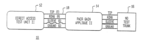
BRIEF DESCRIPTION OF THE DRAWINGS
Figure 1 diagrammatically illustrates the
interconnection of a plurality of telephone system
operation control units within a central offioe~
Figure 2 schematically illustrates a communication
and sleeve lead control circuit arrangement in accordance
with the present inventions and
Figure 3 shows the format of a data communication
message used by the arrangement of Figure 2 for
transmitting reply messages from the pair gain unit to
the DATU.
DETAILED DESCRIPTION
Figure 1 diagrammatically illustrates the
interconnection of a plurality of telephone system
operation control units within a central office 10, in
particular a direct access test unit (DATU) 12, a pair
gain applique (pGA) unit 14 and a no-test trunk (NTT) 16
that are coupled _ to ane another by way of a mufti-lead
telephone link 18, containing respective tip T, ring R,
sleeve S and ground G leads, as shown. As described in
the above-referenced Chan at al application, DATU 12
allows a craftsperson a~ a remote location to control the
operation of no-test trunk 16 and thereby perform test
functions on any subscriber line withaut the need for
participation by central office personnel. To augment its
ability to test subscriber lines nth.er than those
originating in the central office, the system may contain
one or more auxiliary control units, such as pair gain
applique unit 14 which affords access to and testing of
pair gain system telephone lines.
As noted earlier, DATU 12 controls the operation of
no-test trunk 16 by placing sleeve lead S into one of
five prescribed current flow states, comprising open
sleeve (no cu~°rent flow), low negative sleeve, high
negative sleeve, low positive sleeve and high positive
sleeve. Moreover; transitions between two different
~~~ 9yi~ ~97~ pcrius~zia26~'
~~~~~~9~
6
sleeve states may be used to invoke preselected no-test
trunk operations. Thus, for example, where the circuit is
referenced to negative battery rails, the DATU may employ
sleeve lead current flow transitions among low and high
negative polarity current flaw and an open circuit
condition (no current flow) to establish a set of no-test
trunk control functions as follows>
OPEN TO HIGH NEGATIVE
Requests the attention of the no-test trunk. The
sleeve lead is previously in the "idle" state (open), so
that equipment wishing to use the. no-test trunk must
request recognition.
HIGH NEGATIVE TO LOW NEGATIVE
Follows the dial pulsing or multifrequency tone
generation of the digits of the subscriber's line to be
tested on the no-test trunk. The no-test trunk is placed
in a ''cut-through" state, where the equipment attached to
the no-test trunk is, in turn, connected to the
subscriber°s line to be tested. Since the equipment
employs low negative sleeve, the equipment will be
connected outward, towards the subscriber's drop. The
subscriber°s tip and ring will be available for the
equipment connected to the no-test trunk.
LOW NEGATIVE TO OPEN
Puts the no test trunk in a "hold" state. In this
state, the no-test trunk does not drop' the subscriber's
line to which it' is connected, but rather waits for
further instructions about what to is to done with the
line. The subscriber's tip and ring are not available
for use by'the equipment during the open sleeve state.
OPEN TO hOW NEGATIVE
Instructs the no-test trunk to return from the
"hold'° state previously requested by'a "low negative to
open" transition. After this transition, the no-test
trunk is in the same state it was in following the "high
wo 9~n ~~~s Pcrius~~~ozs~~
~~~~~a~~~
negative to low negative" transition (i,e., the
subscriber's tip and ring are once again available for
the equipment's use).
LO~~l NEGATIVE TO HIGH NEGATIVE
Requests disconnection from the subscriber's line.
HIGH NEGATIVE TO OPEN
Places the no-test trunk in an "idle" condition.
Equipment connected to the no-test trunk has no further
requests at this time.
The present invention augments the use of the sleeve
lead to perform the above-enumerated test unit control
functions, by enabling the sleeve lead to carry data
communication signals between telephone system operation
control units, such as the above-referenced DATU and a
pair gain applique unit, while maintaining the integrity
of the current flow state of the sleeve lead as seen by
the no-test trunk and thereby preventing disruption of
the intended control of the operation of the no-test from
the DATU during the exchange of data communications
between the DATU and the pair gain unit.
For this purpose, the pair gain applique is modified
to include a communication and sleeve lead control
circuit axrangement'schematically illustrated in Figure
2 as comprising a first, 'sleeve in' port 21, to which a
sleeve lead S21 from DATU 12 is coupled,. and a second,
'sleeve out' port 2.2 to which a sleeve lead S22 to the
no-test trunk 16 is coupled. 'Sleeve in' port 21 is
coupled ~to a first terminal 31 of a first sleeve lead
bridging relay or switching eircuit 30 comprised of set
of ganged relay' contacts 32, 34 which are controllably
switched between normally open and normally closed
positions by a relay coil 35. Relay coil 35 is
controllably energized by a relay soil driver 30D in
accordance with a control signal from a micro-controller
l00 at control node 30C. Control node 30C, like control
nodes fnr each of the respective relays of the circuit,
as well as activity detection nodes, to be described
w0 9zli797~ P~flUS92/026~7
s
below, is coupled to a micro-controller communication bus
90 through which sensor activity signals from respective
detection nodes in the control circuit and output control
signals from supervisory control micro-controller 100 are
coupled in the course of operation of the circuit. Micro-
controller is driven by pair gain application software in
an on-board control memory. Since the details of the pair
gain application program are not necessary for an
understanding of the present invention, they will not be
described here. Instead, circuit operations effected by
that aspect of the control program which controls the
sleeve lead communication and control arrangement of
Figure 2 will be described below in farms of actually
detected sleeve lead activity states and control signals
the are asserted by the micro-controller in response to
those states.
'Sleeve out' port 22 is coupled to a second terminal
33 of relay 30. A third terminal 36 associated with relay
contact 32 is coupled to a sleeve. lead activity (current
flows detector 40 and to a fourth terminal 37, associated
with relay contact 34. In the de-energized state shown in
Figure 2, relay 30 provides a sleeve lead communication
path from 'sleeve in ' port from the DATU, through the
normally closed switch contacts of relay 30 and to the
'sleeve out' port 22, to which the sleeve lead to the no-
test trunk is connected.
A fifth terminal 38 of relay 30, associated with
relay contact 32, is coupled via link 42 to one side of
a normally open relay contact 52 of a second reply
message 'modulation' relay or switching circuit 50. Relay
50 has a relay winding 55, which is controllably
energized by a relay coil driver 50D in accordance with
a control signal from a micro-controller at control node
50C. A second side of relay contacts 52 is coupled via
link 49 to a sleeve lead state detector 70.
wo 9mo~7~o6 Pcrivsy~ioas~7
A sixth texnninal 39 of relay 30, associated with
relay contact 34, is coupled via link 46 to one side of
a normally open relay contact 62 of a third sleeve open
relay or switching circuit 60. Relay 60 has a relay
winding 65, which is controllably energized by a relay
coil driver 60D in accordance with a control signal from
a micro-controller at control node 60C. A second side of
normally open relay contact 62 is coupled via link 63
through a sleeve lead current monitor circuit 80 to an
sleeve lead output current driver 82 to which a sleeve
output current control node 84 is coupled. As pointed out
previously, as is the case of each of the control nodes
for the respective relays, sleeve current driver control
node 84 is coupled to a micro-controller communication
bus 9o through which sensor activity signals from
respective detection nodes in the control circuit and
output control signals from a supervisory control micro-
controller 10o are coupled.
sleeve lead current monitor circuit 8o comprises an
electro-optic coupler circuit 85, coupled across resistor
87 which is in circuit with an LED 89 at the output of
sleeve lead output current driver 82. A sleeve lead
resistor 91 is coupled between a node 93 and a negative
high voltage terminal 95. Depending upon the output state
of sleeve lead output driver 82, as defined by the
control signal applied to its control node 84 from the
micro-controller, sleeve lead termination resistor 91
will either be in series with sleeve lead resistor 87
(node 93 being at a J,ess negative potential than terminal
95), thereby producing a high sleeve lead resistance or
low sleeve lead current state) or effectively bypassed
(node 93 being at the same potential as terminal 95).
Sleeve lead current monitor circuit 80 has an
output nods 89 coupled to micro-controller bus 90. The
binary level at node 89 is employed by miero-controller
100 in order to confirm whether or not the central office
has removed its termination resistance on the sleeve
wo ~zm ~9~6 Pcmus~ziozss~
to
output lead to praduce an open circuit, or no sleeve lead
currant flow, condition.
Sleeve current flow detector 40 comprises an
electro-optic coupler l05 having a sleeve current active
output node 110. Node 110 is normally biased high
through termination resistor 112 to negative voltage
terminal 114. In response to sleeve lead current flow,
electro-optic coupler 40 turns on, driving node 110 low
(-48V), thereby informing the micro-controller that the
DATU has asserted sleeve lead current.
Sleeve lead state detector 70 comprises a first
electro-optic coupler 120 coupled in circuit with lead 49
from current modulation relay circuit 50. It also
includes a second electro-optic coupler 130 coupled via
a differential threshold circuit 140 to line 49.
Differential threshold circuit 140 sets the threshold
response of electro-optic coupler 130 to a high sleeve
current level (low sleeve lead resistance asserted by the
DATU}, while electro-optic coupler 120 is responsive to
both low and high magnitude sleeve curx~entso As a result,
during a low sleeve state (DATU asserts high sleeve
resistance) output node 125 fram electro-ogtic coupler
120 goes low, whereas output node 135 of electro-optic
coupler 130 stays high. For a high sleeve state (DAmU
asserts low sleeve resistance}, both output node 125 of
electro-optic coupler 120 and output nade 135 of electro-
optic coupler 130 go low. For an open sleeve (no current
flow) condition, neither electro-optic coupler turns on,
so that both nodes 125 and 135 stay high. Nodes 125 and
135 are coupled to micro-controller bus 90 and are
monitored by micro-controller 100 for setting the
magnitude of sleeve lead current applied to output sleeve
lead S22 by sleeve lead current driver 82.
'CVO 93/1797b PCTfUS92/02687
~~,a~~~~~
m
0p~~mTOrr
Tn its idle state configuration shown in Figure 2,
with each of relays 30, 50 and 80 de-energized, sleeve
lead input port 21 is directly coupled through, the
normally closed contacts 32, 34 of relay 30. 80 long as
there is no sleeve current flow (sleeve lead open
circuited) the output node 110 of electro-optic coupler
105 remains high. In response to the DATU asserting
(negative) sleeve current high or low, electro-optic
coupler 40 senses the change in state and causes node 110
to-be asserted low. Tn response to node 110 going low,
micro-controller 100 enables relay 30 via control node
30C and relay circuit 50 via control node 50C, thereby
coupling~sleeve lead input port 21 to sleeve lead state
detector 70. Depending upon whether the magnitude of the
sleeve current is low or high, one or both of nodes 125,
135 of sleeve lead state detector 70 will b~ asserted
low, in response to which micro-controller 100 applies
either a low sleeve current or high sleeve current
representative control level to sleeve lead current
driver 82..As described above, the output of sleeve lead
output driver 82, as defined by the control signal
applied to its control node 84 from micro-controller 100,
will control whether or not sleeve lead termination
resistor 91 forms part of the sleeve lead resistance to
the no-test trunk. For a low sleeve lead curxent state
asserted on input sleeve lead 521, resistor 91 is placed
in series with sleeve lead resistor 87, producing a high
sleeve lead resistance. Conversely, far a high sleeve
lead current state asserted on input sleeve lead 521,
resistor 31 is effectively bypassed, so that the sleeve
lead resistance is determined. by resistor 87,
corresponding to a low sleeve lead resistance and
replicating, on output sleeve lead 522, a high sleeve
lead current state that has been asserted on input sleeve
lead 521.
i~'O 92/37976 Pt.°f/1US92/026R~,
12
After establishing the requisite sleeve lead
resistance, micro-controller 100 applies an enable signal
to control node 60C of relay circuit 60, thereby closing
its noz-mally open contact 62, thereby coupling the output
of sleeve current driver 82 through closed contacts of
relay circuits 30 and 60 to sleeve lead output port 22.
Thus, the intended sleeve lead current magnitude asserted
by DATU 12 on sleeve lead S21 is replicated via sleeve
lead output port 22 on sleeve lead S22 to no-test trunk
16.
As listed above, for the respective open, low and
high sleeve current flow conditions, DATU 12 may. invoke
any of siat control transitions, depending upon the
current flow state of the sleeve lead. For the present
condition of low or high sleeve current flow, a
transition to the other current flow magnitude (high or
low) will cause a change in state in output node 135 of
sleeve lead state detector 70. Micro-controller 100
responds to this change in state at node l35 by changing
the control input to node 84. As a result, the voltage
at node 93 changes state, causing the series connection
of resistor 91 and negative voltage terminal 95 to either
be removed from or inserted in series with resistor 87,
thereby changing the magnitude of the sleeve current
through lead 63, the closed relay contacts Of relays 30
and 60 and sleeve lead 522.
For a transition from a low or high sleeve current
to an open circuit state, the output of node 110 of
current flow detector changes state from low to high.
Micro-controller 100 measures the length of time that
node 110 remains high in order to determine whether or
not the transition is a DATU control transition directed
to 13TT 16, or whether the transition corresponds to a
data communication inquiry message from the DATU to the
pair gain unit.
w~0 92/7976
PCT/US92/02687
~'~p~e~~(3
13
As noted earlier, in accordance with the invention,
data communication messages from the DATU consist of
prescribed duration interruptions (60 ms or 120 ms) of
low sleeve lead current. Thus, a low sleeve current
interruption in eaccess of 300 milliseconds will be
identified as a.low sleeve to open transition which puts
the no test trunk in a "hold" state. Namely, the pair
gain unit 'sees' its own transmissions as if transmitted
by the DATU. 2f the pair gain unit sends a binary
'11111', the open interval is 5 'bit times' (syncbit + 4
data bits). With a single bit time of 60 ms, the open
interval is 300 ms.
For either a high sleeve current-to-open transition
or a long duration low sleeve current-to-open transition,
micro-controller 100 terminates sleeve lead current flow
by asserting node 60C high, thereby de-engaging relay 60
and opening relay contacts 62, and causing an open
circuited output sleeve lead. Since the DATU has
terminated current flow in input sleeve lead 521, micro-
contraller 100 may now safely de-energize relay 30 and
return contacts 32 and 34 to their original normally
closed, idle condition. Also, relay 50 is de-energized,
in order to open the current flow path through link 49 to
sleeve lead state detector 70.
DATA COMMUNICATTONS
DATU-TO-PAIR GAIN M~BSAG~S
As explained previously, data communication messages
from the DATU take the farm of sleeve lead current
interruptions of a finite duration of either 60 ms or 120
ms. These prescribed current interruptions are reflected
by corresponding changes in state of current detector
node 110. Unlike the case of a control transition,
however, micro-controller 100 does not respond by
changing the sleeve current applied to the sleeve lead
output port 22. Tnstead, relays 30 and 60 remain
energized, so as to maintain the sleeve current flow path
from node 93 to sleeve lead output part 22. Micro-
WO 92/17975 PCT/US92/026R1
14
6~~ t~ ~~~~~
controller 100 responds to the DATU inc,~uiry message with
a five-bit reply message having a format in the exemplary
massage shown in Figure 3. Specifically, a reply message
consists of a first synchronization '1' bit followed by
four data bits, where a '1' bit is represented by an
interruption of current flow (open circuit condition) for
a continuous period of 20 ms within a respective 20 ms
bit period.
Micro-controller 100 sources return message to the
DATU by controllably interrupting. the low current
condition on sleeve lead S21 from DATU 12. Far this
purpose, micro-controller 100 initially de-energizes
relay 50 for an initial 60 ms, thereby opening the
current flow path aver lead 42 and lead 49 to sleeve lead
state detector 70. This interruption of the sleeve lead
current path through line 49 is reflected as a 60 ms open
circuit pulse on sleeve lead S21 to DATU 12. Depending
upon the particular reply message to be generated, as
tabulated in the Table below, micro-controller 100 will
controllably open relay 50 to produce one of the bit
sequences of the Table. At the end of the 300 ms
interval of the reply message, the previous sleeve lead
state is restored, by a steady state energizing 8f relay
50 and providing a continuous sleeve lead current path
through its closed contact 52.
TABLE
0000 (0)'- Processing
0010 (2) - Local Line
0011 (3) - Good Single Party Line
0100 (4) - Gaod Cain Tine
0101 (5) - Bad Channel
0110 (6) - Bypass Pair busy or
PGTC
Failure
0111 (7) PGTC in Alarm
1000 (8) - Channel Not Available
1001 (9).Pair Gain Line
1010~ (A) Good Multi-Party Line
1011 (B) RESERVED
~zoi (C) RESERVED
1,01 (D) RESERVED
1110 ~E) - RESERVED
1111 (F) - RESERVED
~~'O 92/1797, ~(°f/11~92/U26$7
As will be appreciated from the faregoing
description, the present invention takes advantage of the
availability of the sleeve lead for auxiliary signalling,
such as controlling the operation of a no-test trunk, by
installing within a pair gain unit, through which the
sleeve lead is coupled between a controlling direct
access test unit and a no-test trunk, a communication and
sleeve lead control apparatus which enables the DATU to
use the sleeve lead to conduct data communications
between itself and the pair gain unit, while maintaining
the integrity of the current flow state of the sleeve
lead as seen by the no-test trunk, thereby preventing
disruption of the intended control of the operation of
the no-test trunk from the DATU during the exchange of
data communications between the DATU and the pair gain
unit. The data communication and control arrangement
according to the invention effectively isolates the
sleeve lead to the no-test trunk from sleeve lead to the
DATU so that the data communications between the DATU and
the pair gain unit are transparent to the no-test trunk.
While we have shown end described an embodiment in
accordance with the present invention, it is to be
understood that the same is not limited thereto but is
susceptible to numerous changes and modifications as
known to a person skilled in the art, and we therefore do
not wish to be limited to the details shown and described
herein but intend . to cover all such changes and
modifications as ar~ obvious to one of ordinary skill in
the art.
S