Note: Descriptions are shown in the official language in which they were submitted.
WO 92/00046 PCI/US91/02542
- -1- 2085376
POROUS FIXATION SURFACE
BACKGROUND OF THE lN V~N l lON
Field of the Invention
The invention relates to a skeletal prosthetic implant
containing a bonded porous fixation structure on its surface.
More particularly, the porous ingrowth structure is comprised
of at least one slotted plate diffusion bonded to the surface
of a metal prosthetic implant or bonded in a recess formed on
the surface.
Description of the Prior Art
Tissue ingrowth surfaces intended to improve fixation of
prosthetic implants have experienced increasing accep-tance
in the orthopedic field in recent years. In the past, most
implants were fixed using a polymethyl metha-crylate bone
cement to achieve prosthesis fixation. However, recent
experience has shown that fixation utilizing tissue ingrowth
into porous coated implants has achieved success rates
equivalent to prostheses fixed with cement.
In most cases, the porous structures or coatings utilized
to create fixation by tissue ingrowth were loosely packed
sintered metal powders, kinked pressed metal fibers, woven
metallic meshes, or expanded metal sheets as well as porous
polymeric materials.
Examples of tissue ingrowth surfaces in the form of
meshes are shown in U.S. Patents 3,905,777, 3,938,198,
4,089,071, 4,261,063, 4,536,894, 4,636,219, 4,644,942,
4,813,959, 4,813,960, 4,863,474 and 4,863,475.
Examples of metallic particles bonded to the surface
of orthopedic implants to encourage tissue ingrowth are shown
in U.S. Patents 3,605,123, 4,542,539, 4,550,448 and
3,855,638. U.S. Patent 4,599,085 relates to an implant
member comprising sintered metal plus bioactive ceramics
which encourage tissue ingrowth.
W092/OW~ PCT/US91/02~2
2085376
U.S. Patent 4,660,755 relates to the use of resistance
welding to bond meshes to a substrate.
U.S. Patent 4,854,496, relates to a porous metal coated
implant where spherical particles are diffusion bonded to an
implant made from titanium.
Each of these structures has its own characteristic
porosity, which is a function of the materials and processes
used to create the structure. While porous structures may
vary from coating to coating, within a given porous coating,
the structural porosity is normally constant, and can be
defined in terms of pore size, pore size distribution and
overall pore volume. It is difficult to vary these
structures to form a wide variety of pore sizes and pore size
distributions.
Even in clinically successful uses of the prior art
tissue ingrowth structures, the ingrowth of biological tissue
is found to be somewhat sporadic in a variable composition
and comprised of substantial amounts of soft connective
tissues with only partial proportions of bone. Fixation is
enhanced where larger amounts of bone or hard connecting
tissue grows into the prosthesis surface rather than merely
soft connective tissue. Laboratory histolo-gical examination
of retrieved clinical human implants and experiments
conducted in animals have shown that there is
a relationship between the pore size and ingrown bone
quality. It has been found that fine pores encourage soft
connective tissue ingrowth while larger pores favor hard or
bone tissue ingrowth. It has also been found that hard or
dense cortical bone exhibits a faster ingrowth rate than
spongy cancellous bone. In general, tissue ingrowth develops
a preferential orientation in response to the direction of
- loading applied across the-implant-bone interface.
The present invention utilizes these relationships
between ingrowth tissue quality, coating pore size and the
relationship of the loads applied between the prosthesis and
bone interface to produce a porous ingrowth surface which can
be easily tailored to take advantage of these known design
.~
_ 3 2 08 53 7 6 64680-613
parameters. The present invention, therefore, is in contrast with
existing coatings. The prior art coatings offer no provision for
tailoring the porous coating as necessary to address the
variability of bone at the surgical sight or to achieve a
preferred tissue orientation to resist anticipated in-service
loading.
SUMI~ARY OF THE INVENTION
The invention provides a prosthetic orthopaedic implant
comprising: a metal hase member defining an outer surface for
implantation adjacent a prepared bone surface, said outer surface
including a recessed area of predetermined shape and depth; a
first metal plate having said predetermined shape and having a
plurality of cross-members having a predetermined lenyth separated
continuously along the length thereof by elongated slots, said
plate fixedly attached to said recessed area of said base member;
and a second metal plate having said predetermined shape and
having a plurality of cross-members separated by elongated slots
fixedly coupled to said first metal plate, said cross-members of
said second plate angularly offset with respect to said cross-
members in said first plate.
The invention also provides a prosthetic orthopaedicimplant comprising: a base member defining an outer surface for
implantation adjacent a prepared bone surface; spacer means fixed
to at least a portion of said outer surface of said base member;
and at least one plate having a plurality of cross-members, each
cross-member extending a predetermined length across a substantial
portion of said plate wherein adjacent cross-members are separated
continuously along the length thereof by an elongated opening
,-/'
3a 2 0 8 5 3 7 6 64680-613
therethrough, said plate fixed to said spacer means and spaced a
predetermined distance from said outer surface of said base member
by said spacer means.
The spacer may be in the form of a second rigid plate
also having a plurality of openings therethrough which communicate
with the plurality of openings in the first plate. The openings
in both the first and second plates may be in the form of
elongated slots which, on each plate,
WOg2/OW~ PCT/US91/02~2
2085376 ^ ~
-4-
extend in a parallel direction. In order to form the pores,
the parallel slots on each plate are angularly offset from
one another with the amount of angular devia-tion determining
the pore size with the largest pore size occurring when the
parallel slots on each plate are orien-tated at an acute
angle to one another.
The spacer may also be in the form of discreet protru-
sions or posts formed in the outer surface of the base member
or may be in the form of parallel ribs exten~ing across the
outer surface of the base member. The outer rigid plate
would then be affixed by any convenient manner to these
protrusions. For example, if the base member and plates are
made of metal, resistance welding or diffusion bonding may be
utilized to form an integral structure. If the base member
is a fiber-reinforced thermosetting resin structure then the
plate may be attached as part of the thermofietting process or
may be affixed to the surface by suitable bonding agents.
The spacers and the outer rigid plate may be placed in a
recessed area of the outer surface of the base member. This
recessed area has a predetermined shape and depth which
cooperates with the spacer and plate thickness to place the
outer surface of the rigid plate continuous with the non-
recessed area of the outer surface.
It should be noted that the fixation surface of the
present invention can be utilized in both cementless and
cemented applications. In a cementless application, the pore
size is controlled to induce tissue ingrowth into the porous
structure and the orientation is designed to resist stresses
transferred directly from the bone. In a cemented
application the pore size and orientation is designed to
produce better adhesion between the cement and the pros-
- thesis and better resistance to anticipated loading.
These and other objects and features of the present
invention will become apparent from the following detailed
description considered in connection with the accompanying
drawings, which disclose several embodiments of the inven-
tion. It is to be understood that the drawings are to be
W092/~W~ 2 0 8 5 3 7 6 PCT/US91/02~2
--5--
used for purposes of illustration only, and not as a defi-
nition of the limits of the invention.
BRIEF DESCRIPTION OF THE DRAWINGS
In the drawings, wherein similar reference characters
denote similar elements throughout the several views:
FIG. 1 is a view in the medial-lateral plane of an
implanted hip prosthesis having the fixation surface of the
present invention with the bone cut away;
FIG. 2 is an enlarged view of the fixation surface shown
in FIG. 1;
FIG. 3 is a cross-sectional view of the prosthesis along
lines 3-3 of FIG. 2;
FIG. 4 is a side view of the rigid tissue ingrowth plates
of the present invention;
FIG. 5 is an exploded isometric view showing the orien-
tation of the rigid plates of FIG. 4 prior to insertion into
a recess in the prosthesis of FIG. 1;
FIG. 6 is a cross-sectional view of a prosthesis having
the tissue ingrowth surface of the present invention bonded
thereto adjacent a bony surface after implantation;
FIG. 7 is an exploded plan view of a tibial prosthesis
having the rigid plates of the present invention as fixa-tion
surfaces prior to assembly;
FIG. 8 is the prosthesis shown in FIG. 7 after assembly
of the rigid plates to the tibial base member;
FIG. 9 is a side view partially in cross-section along
lines 9-9 of FIG. 8;
FIG. 10 is an exploded plan view of an alternate
embodiment for the fixation surface of the present invention
- utilized as a tibial implant;
FIG. 11 is a cross-sectional view through the alternate
embodiment of FIG. 10 after assembly;
FIG. 12 is yet an additional embodiment of the fixation
surface of the present invention as a tibial implant in an
exploded plan view; and
W092/0W~ PCT/US91/02~2
20~5376
- FIG. 13 is a cross-sectional view of the embodiment shown
in FIG. 12 after assembly.
DESCRIPTION OF THE PREFERRED EMBODIMENTS
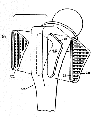
Referring to FIGS. 1-6 there is shown a hip prosthesis
generally denoted as 10 incorporating the fixation surface of
the present invention implanted in a femur 12. The femur 12
of FIG. 1 is cut away in the medial-lateral plane to expose
the fixation surface generally denoted as 14. Fixation
surface 14 is preferably located in a recess 16 formed on
both the anterior and posterior sides of femoral implant 10.
In the preferred embodiment, the fixation surface has the
same shape as recess 16 and has a thickness equal to the
depth of recess 16 so that an outer surface 18 thereof is
continuous with the outer surface 20 of femoral compo-nent
10. Both outer surfaces 18 and 20 are adjacent inner surface
21 of femur 12. While fixation surfaces 14 are shown located
in the medial-lateral plane of the proximal end of the
femoral component 10, it is contemplated that fixation
surface 14 may be placed at any desired location about the
prosthesis and may be curved if necessary to conform to
rounded parts of prosthesis 10.
Referring to FIGS. 4 and 5, it can be seen that fixa-tion
surface 14 includes a spacer plate 22 and an outer plate 24.
The preferred plates 22 and 24 have elongated slots 26 and 28
respectively, formed therein. In the preferred embodiments,
slots 26 of plate 22 are oriented parallel to one another and
slots 28 of plate 24 are oriented parallel to one another.
Plates 22 and 24 have a shape conforming to the shape of
recess 16 formed in the anterior and posterior sides of
prosthesis 10. Inner plate 22 is designed to conform to and
lay flat against the bottom surface 25 of recess 16.
As can be best seen in FIG. 5, plates 22 and 24 are
placed on top of one another and then placed into recess 16
during fabrication of prosthesis 10. If prosthesis 10 and
WO92/ON~K ~ PCT/USgl/02~2
._
_7_ 2~85376
plates 22 and 24 are made of titanium, then the plates are
fixedly attached to prosthesis 10 by either electron beam
welding, resistance welding, laser welding or diffusion
bonding so that they form an integral part of the pros-thesis
S prior to implantation. Referring to FIG. 6, it can be seen
that after implantation outer surface 18 of plate 24 is
adjacent an exposed surface 21 of, in the case of femur 12,
the medullary canal. While in the preferred embodiment
surface 18 is continuous with the surface 20 of the
prosthesis adjacent the recessed area, it may be positioned
slightly above surface 20 to insure contact between surface
21 and surface 18.
Referring again to FIG. 4, it can be seen that parallel
slots 26 of plate 22 are oriented perpendicularly with
respect to parallel slots 28 in plate 24. It can be seen
that by varying the angular orientation of slots 26 and 28
with respect to one another between 0 and 90 , openings or
pores of various sizes and shapes are produced. The pores
can be made very small or relatively large depending on the
angular orientation. All that is required is that there is
some communication between openings 26 and 28 to allow tissue
to grow into the structure and around cross-members 27 and 29
to thereby lock the prosthesis to the bone structure. It can
be seen that while in the preferred embodiment, two plates
are utilized to form the porous ingrowth structure, three or
even more plates could be utilized to form even more
intricate variations in pore size and orientation.
Furthermore, other opening patterns such as holes, zig-zag
slots or polygonal openings can be used on each plate instead
of parallel slots.
The porosity of the structure can also be varied by
- varying the width of elongated slots 26, 28 and therefore the
width of cross-members 27, 29. In the preferred embodiment,
the slot width is approximately 1 mm with the cross-members
separating the elongated slots having a width of about 1.3
mm. Preferably, plates 22 and 24 have a thickness of at
least .7 mm and the flexibility of the plates can be varied
WO92/OH~6 2 0 8 5 3 7 6 PCT/US91/02~2
-
by varying the material thickness. Utilizing two plates with
the dimensions described above, and with the elongated slots
and cross-members oriented at 4S results in pore openings of
approximately 1 mm X 1 mm, with .7 mm x 1.0 mm, interconnec-
ting passages. This structure is about 55% porous by volume.
Referring now to FIGS. 7 to 9, there is shown a tibial
implant generally denoted as 40 in which plates 42 and 44 are
designed to fit in a recessed area 46 formed in the tibial
tray 48. Again, each plate 42, 44 includes elon-gated slots
50 and 52 respectively, which in turn define cross-members S4
and 56. Again, slots 50 and cross-members 54 of plate 42 are
oriented parallel thereon and slots 52 and cross-members 56
of plate 44 are likewise oriented parallel on that plate. As
described herein above, the plates are affixed to a metallic
tibial tray 48 by electron beam welding, laser welding or
resistance welding or via thermal diffusion bonding. The
pore size may be varied as described above and the
orientation of the pore structure will be that best suited to
resist transverse forces applied to the tibial prosthesis
after implantation.
Referring to FIGS. 10 and 11, there is shown an alter-
nate emhoA;ment of the porous fixation surface of the present
invention. While the embodiments shown in FIGS. 10 and 11
refer to a tibial implant, the invention disclosed could be
utilized equally well on a hip implant or any other suitable
prosthetic device. In this embodiment,
a plate 60, identical in form to plate 42 previously
described, is placed in a recess 61 formed in a tibial tray
62 which recess includes a plurality of integrally formed
parallel ribs 64 extending outwardly of the surface thereof.
Ribs 64 are preferably cast or forged onto surface 66 of
recess 61. Ribs 64 serve to space plate 60 from surface 66
of recess 61 of tibial tray 62. In the preferred embo-
diment, ribs 64 are again oriented parallel to one another
and, after bonding, a structure exhibits the same porosity as
the fixation surface previously described.
PCT/US91/02~2
W092/O~K 2 ~ `~ 5:3 ~ :~
Referring to FIGS. 12 and 13, there is shown yet another
alternate embodiment in which a plate 70 is spaced above a
surface 72 of a recess 71 in a tibial tray 74 by a plurality
of posts 76. After bonding plate 70 to tibial tray 74, a
much more open structure is formed in this embodiment and, if
nPcpcc~ry~ a second plate (not shown) exhibiting the same
structure of parallel slots and cross-members may be bonded
to post 76 and, in turn, plate 70 to form the necessary pore
structure.
The method of fabricating the structure set forth above
will now be described. The plates may be produced from thin
sheet material, such as titanium sheet, with the slots
therein cut by programmable laser cutting, photo chemical
etching, water jet cutting, wire electrode discharge
mach;ning (EDM) or die stamping and conventional machining.
The preferred method for attaching the plates to the metal
base structure is the use of thermal diffusion bonding. For
this process, the plates are thoroughly cleaned and etched in
a 9.1% HN03-HF solution. The plates are then temporarily
bonded into the cavity formed in the base member in a few
drops of cyano-acrylate adhesive. The plates are then
metallurgically bonded in place by diffu-sion bonding in a
fixture designed to take advantage of differential thermal
eYp~n~ion to generate the pressure required to accelerate
this bonding. Diffusion bonding does not produce any melting
but produces complete bonding across the interface of the
parts to be joined. Diffusion bonding is preferred because
the plates of the present invention have planar contact
surfaces and form an incom-pressible porous structure. This
allows for full trans-mission of pressure during the
diffusion bonding operation.
Metallurgical bonding is achieved in a 1 hour thermal
cycle at approximately 1650 F in a vacuum furnace in an
atmosphere of 10-5 torr. Full interfacial bonds are achieved
in this manner both as to the base member and the spacing
plate and the spacing plate to the outer plate. In the case
of titanium, the implant assembly is chemically milled to
W092/0~ - 2 0 8 5 3 7 6 PCT/US91/02542
--10--
remove all traces of an oxygen enriched alpha case which
would impair the peak performance of the tita-nium implant.
The prosthesis is then finished via abrasive belting,
grinding and mac~in;ng as is normal in completing the
manufacturing cycle.
In order to better resist forces applied to the pros-
thesis after implantation, the plates are placed in the
recesses such that the cross-members of the outermost plate
are oriented perpendicular to the anticipated loading. In a
hip prosthesis this would mean the cross-members would be
oriented perpendicular to the long axis of the prosthesis
stem. When the fixation structure of the present invention
is utilized in a knee prosthesis tibial tray, the outer
cross-members should be oriented at approximately 45- to the
long axis of the tray to achieve a biased pore and rib
alignment suitable for resisting transverse shifting loads
experienced in the knee.
While several examples of the present invention have been
described, it is obvious that many changes and modi-fications
may be made thereunto without departing from the spirit and
scope of the invention.