Language selection

Search

Patent 2085539 Summary

Third-party information liability

Some of the information on this Web page has been provided by external sources. The Government of Canada is not responsible for the accuracy, reliability or currency of the information supplied by external sources. Users wishing to rely upon this information should consult directly with the source of the information. Content provided by external sources is not subject to official languages, privacy and accessibility requirements.

Claims and Abstract availability

Any discrepancies in the text and image of the Claims and Abstract are due to differing posting times. Text of the Claims and Abstract are posted:

  • At the time the application is open to public inspection;
  • At the time of issue of the patent (grant).
(12) Patent: (11) CA 2085539
(54) English Title: LOCKING NAIL FOR TREATING FRACTURES OF THE PROXIMAL FEMUR
(54) French Title: CLOU DE BLOCAGE POUR LE TRAITEMENT DES FRACTURES DU FEMUR PROXIMAL
Status: Expired
Bibliographic Data
(51) International Patent Classification (IPC):
  • A61B 17/58 (2006.01)
  • A61B 17/78 (2006.01)
(72) Inventors :
  • HARDER, HANS ERICH (Germany)
  • GROSSE, ARSENE JEROME (France)
(73) Owners :
  • STRYKER TRAUMA GMBH (Germany)
(71) Applicants :
(74) Agent: SMART & BIGGAR
(74) Associate agent:
(45) Issued: 1998-07-28
(22) Filed Date: 1992-12-16
(41) Open to Public Inspection: 1993-07-15
Examination requested: 1993-02-10
Availability of licence: N/A
(25) Language of filing: English

Patent Cooperation Treaty (PCT): No

(30) Application Priority Data:
Application No. Country/Territory Date
G 92 00 328.1 Germany 1992-01-14

Abstracts

English Abstract


A locking nail for treating fractures of the proximal femur, in
particular of subcapital fractures, comprising a nail shaft
including a cross-bore for receiving a bone screw in its distal
end portion and a pair of inclined bores for receiving femur neck
screws in its proximal portion, whereby the proximally located
angular bore has a larger diameter than the associated femur neck
screw.


French Abstract

L'invention porte sur un clou de blocage pour traiter les fractures du fémur proximal, plus particulièrement les fractures sous-capitales. Le clou est formé d'une tige comprenant un alésage transversal, pour recevoir une vis pour os à l'extrémité distale, et une paire d'alésages inclinés, pour recevoir des vis pour col du fémur dans la partie proximale. L'alésage angulaire se trouvant dans la partie proximale présente un diamètre plus grand que celui de la vis pour col du fémur associée.

Claims

Note: Claims are shown in the official language in which they were submitted.


THE EMBODIMENTS OF THE INVENTION IN WHICH AN EXCLUSIVE
PROPERTY OR PRIVILEGE IS CLAIMED ARE DEFINED AS FOLLOWS:

1. A locking nail for treating subcapital fractures, comprising a nail
shank having a proximal end portion and a distal end portion, the distal end
portion having a cross bore for receiving a bone screw, the proximal portion
including a pair of oblique bores adapted to receive femur neck screws, the
oblique bores having an axis inclined relative to the longitudinal and a transverse
axis of the nail shank and being spaced along the longitudinal axis of the nail
shank, at least one of the neck screws for the proximally located oblique bore
having a cylindrical portion, with the proximally located oblique bore having a
larger diameter than the cylindrical portion of the associated neck screw such that
it can be oriented in different angular positions.

2. The locking nail of claim 1, wherein the cross section of the proximal
oblique bore is oval.

3. The locking nail of claim 1 or 2, wherein the length of the nail shank
between the distal end portion and the distally located oblique bore is maximally
1.5 times the length of the nail shank between the proximal end portion and the
distally located oblique bore.

4. The locking nail of claim 1, wherein the nail shank is formed

- 6 -


substantially cylindrical in its proximal end portion and conically in its distal end
portion.

5. The locking nail of claim 1, wherein the nail shank is curved in the
lateral medial plane to suit the natural curvature of the femur.

6. The locking nail of claim 1, wherein the nail shank comprises an
axially extending bore.

7. The locking nail of claim 1, wherein a single cross bore is provided in
the distal end portion.

- 7 -


Description

Note: Descriptions are shown in the official language in which they were submitted.


J,) ,,1 i~


A Locking Nail for Treating Fractures of the Proximal Femur


The present invention relates to a locking nail for treating
fractures of the proximal femur according to the preamble of
claim 1.

EP 0257118 discloses a locking nail for treating subtrochan-
tic fractures. A nail shaft proximally inserted into the
mallow space of the femur is provided with an obli~ue bore
for receiving the femur neck screw. The locking nail is
distally provided with a pair of cross-bores to receive bone
screws. The femur neck screw is freely axially movable in
the cross-bore and the locking nail is provided with a
securing means selectively preventing a turning of the femur
neck screw but allowing an axial displacement. For an osteo-
synthesis supplement of such type the locking nail is not
used per se for treating the fracture, but is provided to
guide and hold the femur neck screw.


It is further known to provide a distang pair of oblique
bores in the proximal end portion of a locking nail to
receive a pair of femur neck screws.

The locking nails used for the known osteosynthesis aids are
designed to be relatively long so that the femur is hurt
over almost its total length when being driven in. When a
pair of femur neck screws is used, they both are located
within a plane which does not always fit to the conditions
to be met, in particular in case of subcapital fracture~.

Therefore, it is the object of the present invention to pro-
vide a locking nail which is particularly suited for treat-
ing subcapital fractures.

According to the inventior. ~he object is solved by the fea-
tures of claim 1.


~ ~ ~3 ~ ~ .3 ~


According to the invention the oblique bore at a proximal
portion of the nail shaf~ has a larger diameter than the re-
spective femur neck screw. Preferrably, the proximal angular
bore s shaped as an elongated bore in an axis perpendicular
to the nail axis. In this manner, the femur neck screw in-
serted may pivot in the angular bore to some limited extent
to be oriented in a desired way. In particular, the screw
may be positioned in an angular position substantially dif-
ferent with respect to the position of the other femur neck
screw. This is of a particular advantage in treating sub-
capital fractures.
According to a further embodiment of the invention the nail
shaft is shaped to be relatively short. The proximal portion
of the nail shaft is formed substantially cylindrical, while
conically tapering towards the distal end in the distal
area. The length of the nail shaft between the distal end
and the distal angular bore -x; -lly is 1.5 times the
length between the pro~ l end and the distal angular bore.
Therefore, the femur is in; -lly hurt only when implanting
the nail shaft.
According to the invention the proximal portion of the nail
shaft has a relatively large diameter. There is an advan-
tage, therefore, when the nail shaft is curved in the late-
ral medial plane to fit to the natural curvature of the
femur.
According to a still further embodiment of the invention the
nail shaft is AXi~ I ly provided with a length bore. Thus the
nail shaft may be driven in by means of a guide lance.
Since the nail shaft is relatively short, a further embodi-
ment of the invention provides for a single cross-bore in
the distal end portion to lock the nail in the femur. -

By way of an example, the invention will now be de~cribedwith reference to the acc. ~-nying drawing.

~ iJ ~3~3~


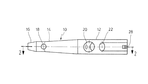
Fig. 1 is a side view of a nail ~haft of the locking nail
according to the invention,
Fig. 2 is a section through the locking nail portion of
Fig. 1 along the line 2-2,
Fig. 3 i5 a side view of a femur neck screw for the nail
shaft of Figs. 1 or 2,
Fig. 4 is a side view of an ~lternative femur neck screw
for tha nail of Figs. 1 and 2, and
Fig. 5 is a sec~ion through the femur neck screw of Fig. 4
along the line 5-5.
A nail shaft 10 forming part of a locking nail comprises a
cylindrical portion 12 in the proximal area and a substan-
tially conical portion 14 in the distal area. The total
length is 120 mm for e~ample, wherein both the portions 12,
14 are substantially of equal length. As may be seen a trun-
cated tip 16 is formed at the first tapered portion of the
nail portion 14. The distal end portion is provided with a
cross- bore 18 for receiving a bone screw not shown. In the
proximal portion, or respectively the section 12 a pair of
angular inclined bores 20 and 22 is provided for receiving
femur neck screws shown in Figs. 3 to 5. The angle of the
oblique bores 20, 22 which is equal for both bores may be
between 25~ and 40~ relative to a vextical on the length
axis of the nail shaft lO.
As Fig. 2 shows, the nail shaft 10 is curved in the lateral
- i~l plane corresponding to the na~ural Gurvature of the
human femur. The nail shaft 10 further includes a length
bore 24 extending in correspondence to the curvature of the
nail (Fig. 2). At the proximal end the length bore is ex-
tended to a threaded bore 26. For example it serves to re-
ceive a suited positioning device ~not shown). Furthermore,
the proximal end includes a recess 28 which is suited to

~i~g 3~


orient the positioning device to be applied as well to
rotate the nail in a desired rotational position when driv-
ing in.
The angular bore 20 having a larger diameter receives a
femur neck screw 30 as shwon in Figs. 4 and 5. The illu-
stration of the femur neck screw in Figs. 3 to 5 is not on
scale. Accordingly, the femur neck screw 30 has a diameter
which is ~inir~lly smaller only than the diameter of the
angular bore 20. The femur neck screw 30 includes a cylin-
drical shaft 32 having a length bore 34. At the front end a
thread 36 is formed which is self-cutting by a cutting
groove 38. At the rearward region a pulurality of peripher-
ally distant grooves 40 is formed which extend parallel to
the axis. The grooves may receive the free end of a screw
which is turned into the threaded bore 26 to fix the femur
neck screw 30 in a rotational position, but allows an axial
displacement as disclosed in the European Patent 257118
above referred to. A fixing of the femur neck screw 30 of
this type is accomplished only then, however, when there is
no femur neck screw inser~ed through the second angular bore
22. The femur neck screw 30 has an end portion including an
inner threaded bore 38 to mount a suitable inst~ . Four
recesses 42 equally spaced peripherally allow to apply a
turning force.
A femur neck screw 44 is inserted through the angular bore
22 which screw has a cylindrical shaft portion 46 extending
into a tapered shaft portion 48 towards the end at which a
threaded portion 50 is formed. The head 52 of the femu~ neck
screw 44 comprises an inner hexagonal recess 54.
Fig. 1 shows that the angular bore 22 is not circular, but
oval. When the diameter of the cylindrical shaft portion 46
is 6.5 mm for example, the large ~i~ ~Ler of the angular
bore 22 amounts to 10 mm. As may be seen, the large diameter
of the cross-sectional area of the bore 22 extends oblique


... .... . . ... .. . . .. . . .. ... .


s


with respect to the longitudinal axis of the nail shaft 10.
Therefore, the femur neck screw 44 may be oriented with
respect to the angular bore 22 in accordance with the
conditions to be met.

Representative Drawing
A single figure which represents the drawing illustrating the invention.
Administrative Status

For a clearer understanding of the status of the application/patent presented on this page, the site Disclaimer , as well as the definitions for Patent , Administrative Status , Maintenance Fee  and Payment History  should be consulted.

Administrative Status

Title Date
Forecasted Issue Date 1998-07-28
(22) Filed 1992-12-16
Examination Requested 1993-02-10
(41) Open to Public Inspection 1993-07-15
(45) Issued 1998-07-28
Expired 2012-12-17

Abandonment History

There is no abandonment history.

Payment History

Fee Type Anniversary Year Due Date Amount Paid Paid Date
Application Fee $0.00 1992-12-16
Registration of a document - section 124 $0.00 1993-06-22
Maintenance Fee - Application - New Act 2 1994-12-16 $100.00 1994-09-07
Maintenance Fee - Application - New Act 3 1995-12-18 $100.00 1995-09-11
Maintenance Fee - Application - New Act 4 1996-12-16 $100.00 1996-12-06
Maintenance Fee - Application - New Act 5 1997-12-16 $150.00 1997-09-08
Final Fee $300.00 1998-03-26
Maintenance Fee - Patent - New Act 6 1998-12-16 $150.00 1998-12-10
Maintenance Fee - Patent - New Act 7 1999-12-16 $150.00 1999-11-04
Maintenance Fee - Patent - New Act 8 2000-12-18 $150.00 2000-11-03
Registration of a document - section 124 $100.00 2000-12-18
Maintenance Fee - Patent - New Act 9 2001-12-17 $150.00 2001-10-17
Maintenance Fee - Patent - New Act 10 2002-12-16 $200.00 2002-11-05
Maintenance Fee - Patent - New Act 11 2003-12-16 $200.00 2003-10-08
Maintenance Fee - Patent - New Act 12 2004-12-16 $250.00 2004-10-15
Maintenance Fee - Patent - New Act 13 2005-12-16 $250.00 2005-08-12
Maintenance Fee - Patent - New Act 14 2006-12-18 $450.00 2007-04-03
Maintenance Fee - Patent - New Act 15 2007-12-17 $450.00 2007-10-19
Maintenance Fee - Patent - New Act 16 2008-12-16 $450.00 2008-10-23
Maintenance Fee - Patent - New Act 17 2009-12-16 $450.00 2009-10-29
Maintenance Fee - Patent - New Act 18 2010-12-16 $450.00 2010-10-18
Maintenance Fee - Patent - New Act 19 2011-12-16 $450.00 2011-10-27
Owners on Record

Note: Records showing the ownership history in alphabetical order.

Current Owners on Record
STRYKER TRAUMA GMBH
Past Owners on Record
GROSSE, ARSENE JEROME
HARDER, HANS ERICH
HOWMEDICA GMBH
Past Owners that do not appear in the "Owners on Record" listing will appear in other documentation within the application.
Documents

To view selected files, please enter reCAPTCHA code :


To view images, click a link in the Document Description column. To download the documents, select one or more checkboxes in the first column and then click the "Download Selected in PDF format (Zip Archive)" or the "Download Selected as Single PDF" button.

List of published and non-published patent-specific documents on the CPD .

If you have any difficulty accessing content, you can call the Client Service Centre at 1-866-997-1936 or send them an e-mail at CIPO Client Service Centre.


Document
Description 
Date
(yyyy-mm-dd) 
Number of pages   Size of Image (KB) 
Claims 1998-06-01 2 42
Cover Page 1993-12-14 1 17
Abstract 1993-12-14 1 11
Drawings 1993-12-14 1 23
Claims 1993-12-14 1 36
Description 1993-12-14 5 178
Claims 1997-12-03 2 42
Cover Page 1998-07-16 1 35
Claims 1998-05-26 2 42
Representative Drawing 1998-07-16 1 4
Fees 2007-10-19 1 35
Assignment 2000-12-18 2 78
Correspondence 1998-03-26 1 29
Correspondence 2001-11-15 1 17
Fees 2005-08-12 1 35
Prosecution Correspondence 1993-02-10 1 27
Prosecution Correspondence 1997-11-17 4 120
Prosecution Correspondence 1997-11-12 1 38
Examiner Requisition 1997-05-27 2 77
Prosecution Correspondence 1993-08-10 3 73
Fees 2007-04-03 2 61
Fees 1996-12-06 1 74
Fees 1995-09-11 1 38
Fees 1994-09-07 1 45