Language selection

Search

Patent 2085815 Summary

Third-party information liability

Some of the information on this Web page has been provided by external sources. The Government of Canada is not responsible for the accuracy, reliability or currency of the information supplied by external sources. Users wishing to rely upon this information should consult directly with the source of the information. Content provided by external sources is not subject to official languages, privacy and accessibility requirements.

Claims and Abstract availability

Any discrepancies in the text and image of the Claims and Abstract are due to differing posting times. Text of the Claims and Abstract are posted:

  • At the time the application is open to public inspection;
  • At the time of issue of the patent (grant).
(12) Patent: (11) CA 2085815
(54) English Title: ENDOPROSTHESIS FOR THE KNEE-JOINT
(54) French Title: ENDOPROTHESE POUR L'ARTICULATION DU GENOU
Status: Expired
Bibliographic Data
(51) International Patent Classification (IPC):
  • A61F 2/38 (2006.01)
  • A61F 2/30 (2006.01)
  • A61F 2/00 (2006.01)
(72) Inventors :
  • KOTZ, RAINER (Austria)
  • WINDHAGER, REINHARD (Austria)
(73) Owners :
  • STRYKER TRAUMA GMBH (Germany)
(71) Applicants :
(74) Agent: SMART & BIGGAR
(74) Associate agent:
(45) Issued: 1999-11-23
(22) Filed Date: 1992-12-18
(41) Open to Public Inspection: 1993-06-21
Examination requested: 1995-11-08
Availability of licence: N/A
(25) Language of filing: English

Patent Cooperation Treaty (PCT): No

(30) Application Priority Data:
Application No. Country/Territory Date
G 91 15 810.9 Germany 1991-12-20

Abstracts

English Abstract


Endoprosthesis for the knee joint and adjacent bone parts
comprising a femoral and a tibial joint part, a bone replacement
part to be attached to the femoral or, respectively tibial joint
part which replacement part comprises a pair of telescopically
cooperating rod members which are adjusted with respect to each
other by a threaded spindle and a spindle nut, and comprising a
pinion on the spindle to be actuated by a rotating means, whereby
an indexing mechanism is provided comprising an indexing member
which is actuated by the tibial or femoral joint part in an
extreme bending position of the joint.


Claims

Note: Claims are shown in the official language in which they were submitted.


THE EMBODIMENTS OF THE INVENTION IN WHICH AN EXCLUSIVE
PROPERTY OR PRIVILEGE IS CLAIMED ARE DEFINED AS FOLLOWS:
1. Endoprosthesis for the knee joint and adjacent bone parts comprising
a femoral and a tibial joint part, a bone replacement part to be attached to
the
femoral or, respectively tibial joint part which replacement part comprises a
pair of
telescopically cooperating rod members which are adjusted with respect to each
other by a threaded spindle and a spindle nut, and comprising a pinion on the
spindle to be actuated by a rotating means, characterized in that the rotating
means include an indexing mechanism which has an indexing member adapted to
cause a limited rotation of the pinion upon actuation and the indexing member
is
actuated by the femoral or tibial joint part when the knee joint is in an
extreme
bending position.
2. The endoprosthesis of claim 1, wherein said indexing mechanism
includes a ratchet mechanism.
3. The endoprosthesis of claim 2, wherein said indexing member is
defined by a pin which is slidably supported in said other joint part, which
pin
cooperates with a fine toothing of said pinion.
-6-


4. The endoprosthesis of claim 3, including a spring-loaded locking pawl
is provided coacting with a second toothing on the pinion which pawl rotates
the
pinion about half the pitch when the indexing pin disengages a first toothing.
5. The endoprosthesis of claim 3 or 4, wherein the indexing pin is
biases by a spring away from the toothing.
6. The endoprosthesis of claim 4 or 5, wherein the tooth profile of the
teeth of the second toothing along which the locking pawl is moved out of the
second toothing, when the indexing member further rotates the pinion,
degressively slopes upwardly from teeth bottom.
-7-

Description

Note: Descriptions are shown in the official language in which they were submitted.


2085815
The present invention refers to an endoprosthesis for the
knee-joint.
For patients who are still growing and who carry a full
endoprosthesis for the knee-joint for example, an adaptation
to the growth in length is necessary. German petty patent
DE-GM 87 06 999 discloses a so-called growth prosthesis
comprising a pair of telescopically coacting rod members
defining a bone replacement part, wherein a spindle and a
spindle nut provide for a relative adjustment of the rod
members. The spindle of the known prosthesis is coupled to a
bevel gear of which a gear wheel includes a drive pin which
may be actuated from outside the prosthesis. Preferably the
drive pin is located in an area of the joint where the
thickness of the soft tissue is relatively thin so that the
bevel gear becomes accessible by a mere prick incision. It
therefore needs a local anesthesia only to adjust the
prosthesis in length. Nevertheless an operation, although
minor, is necessary resulting in a certain stress and risk the
patient is subjected to.
It is the object of the present invention to provide a length-
adjustable prosthesis for the knee joint including an adjacent
bone portion wherein the length may be adjusted post-operative
without operation.
The invention provides endoprosthesis for the knee joint and
adjacent bone parts comprising a femoral joint part and a
tibial joint part that are interconnected to form a joint, a
- 1 -
74855-4


2fl85815
bone replacement part to be attached to one of said joint
parts which replacement part comprises a pair of
telescopically cooperating rod members which are adjustable
with respect to each other by a threaded spindle and a spindle
nut, and comprising a pinion on the spindle to be actuated by
a rotating means, wherein an indexing mechanism is provided
comprising an indexing member on one said joint part which is
actuated by other of said joint parts in an extreme bending
position of the joint.
- la -
74855-4


2085815
2
According to the invention an index drive is provided in the
prosthesis which is actuated by the tibial or femoral joint
member in a more or less extreme bending position of the
joint. An indexing member of the indexing drive directly
actuates the member to be moved, i.e. a threaded spindle in
steps. The indexing member is actuated in an extreme bending
position which is limited by the geometry of the knee-pros-
thesis to obtain a rotation of the spindle. According to a
preferred embodiment of the invention a ratchet mechanism is
provided in which typically an indexing pawl engages the
teeth of a wheel, whereas a locking pawl locks the indexing
wheel when the driving wheel performs its return stroke.
A number of different structural embodiments is suitable to
build a ratchet mechanism. According to an embodiment of the
invention, the indexing member is defined by a pin which is
slidably supported in the femoral or tibial joint member
which pin coacts with the toothing of a gear wheel. When the
indexing pin is actuated by bending the joint the gear wheel
is driven at a small rotational angle. A repeated bending
and stretching thus results in a corresponding stepwise
turning of the threaded spindle.
When the indexing pin coacting with the tooth flanks of the
gear wheel provides for an indexing of less than the
circular tooth pitch, a spring loaded locking pawl
cooperating with the toothing of the pinion is provided to
rotate the pinion around half the pitch when the indexing
pin is out of engagement with the toothing. Accordingly a
rotation of half the pitch is performed by the pin and the
remaining rotation by the locking pawl.
According to a further embodiment of the invention the
indexing pin is biased by a spring to disengage the toothing
in the normal case.


205815
The invention is described in detail with reference to the
drawings.
Fig. 1 shows a side view, partly in section, of a
prosthesis according to the invention,
Fig. 2 shows a front view of an indexing pinion of the
prosthesis of Fig. 1,
Fig. 3 shows a side view portion of the pinion of Fig. 1 in
the direction of arrow III,
Fig. 4 shows a view illustrating a locking pawl coacting
with the pinion of the prosthesis of Fig. 1.
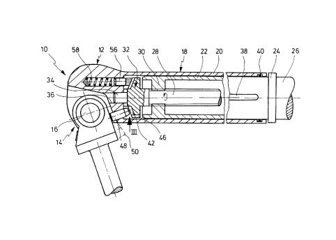
The endoprosthesis shown in Fig. 1 comprises a prosthetic knee
joint 10 of the type of a hinge joint including a femoral
joint portion 12 and a tibial joint portion 14. The joint
portions 12, 14 are pivotably arranged about the rotating pin
16. The tibial joint portion 14 comprises means not shown for
attaching to the human tibia. A bone replacement part 18 is
attached to the femoral joint portion 12. The replacement
part comprises a tube 20 integrally connected to the femoral
portion 12 in which tube an inner-cylindrical part 22 is
telescopically slidingly received. A displacement of the
inner part 22 into the outer part is limited by a radial
flange 24. The side of the flange 24 opposite the part 20 is
connected to a solid shaft 26 comprising means (not shown) for
attaching to the femur. A suitable attachment is shown in
- 3 -
74855-4


X085815
German petty patent DE-GM 87 06 999 for example.
The inner telescopic part 22 is formed partly hollow and
accommodates a threaded spindle 28 cooperating with a spindle
- 3a -
74855-4


2085$15
4
1 nut 30 which is formed by a cross-wall of the inner tele-
scopic part 22. The spindle 28 integrally carries an index-
ing pinion 32 having a front end comprising a pin 34 which
is rotatably supported in a bore 36 of the femoral part 12.
When the spindle 28 is rotated, the telescopic part 22
relatively moves with respect to the telescopic part 20 to
obtain a change in length. The telescopic part 22 is non-
rotatably fixed as indicated at 38. Both the telescopic
parts are sealed with respect to each other as indicated by
the seal 40. The indexing pin comprises a first bevelled
toothing 42 and a second toothing 46 (see Fig. 4 as well).
The femoral part 12 slidingly supports an indexing pin 48
which can be biased by a spring not shown away from the
indexing pinion 32. The indexing pin 48 projects over the
femoral part 42, wherein the outwardly directed motion may
be limited by means not shown. When the tibial part 14 is
further bent with respect to the femoral part, as indicated
in dash-dotted lines 50, the tibial part 14 urges the
indexing pin 48 towards the pinion 32. Accordingly, the
conical
tip 54 of the pin 48 engages an adjacent flank of the
toothing 42 to rotate the pinion 32 about half a pitch of
the toothing 42. A locking pawl 56 in shape of a pin urged
by pressure spring 58 towards the pinion 32 cooperates with
the toothing 46. When the pinion 32 is rotated as mentioned
before, the pawl 56 disengages the toothing. As the indexing
pin 48 rotates the pinion such that the toothing 46 is
rotated about half the pitch or somewhat more, the locking
pawl 46 can enter the next tooth gap to further rotate the
pinion about a certain amount. Repeating the steps referred
to, the spindle is rotated, further resulting in the desired
change of length by moving the inner telescopic part 22 out
of the outer part .


2085815
1 The artisan realises that the indexing mechanism performs a
length adaptation of the prothesis eliminating the need of a
surgical operation.
Fig. 4 shows that the profile of the flanks of the toothing
46 is different. When the locking pin 56 moves out against
the force of the spring 58, the pin 56 slides along a
profile which degressively slopes from the gear bottom
whereas the profile on the opposite side of the tooth forms
a straight inclined ramp.
20
- 25
35

Representative Drawing
A single figure which represents the drawing illustrating the invention.
Administrative Status

For a clearer understanding of the status of the application/patent presented on this page, the site Disclaimer , as well as the definitions for Patent , Administrative Status , Maintenance Fee  and Payment History  should be consulted.

Administrative Status

Title Date
Forecasted Issue Date 1999-11-23
(22) Filed 1992-12-18
(41) Open to Public Inspection 1993-06-21
Examination Requested 1995-11-08
(45) Issued 1999-11-23
Expired 2012-12-18

Abandonment History

There is no abandonment history.

Payment History

Fee Type Anniversary Year Due Date Amount Paid Paid Date
Application Fee $0.00 1992-12-18
Registration of a document - section 124 $0.00 1993-06-29
Maintenance Fee - Application - New Act 2 1994-12-19 $100.00 1994-09-07
Maintenance Fee - Application - New Act 3 1995-12-18 $100.00 1995-09-11
Maintenance Fee - Application - New Act 4 1996-12-18 $100.00 1996-09-12
Maintenance Fee - Application - New Act 5 1997-12-18 $150.00 1997-09-08
Maintenance Fee - Application - New Act 6 1998-12-18 $150.00 1998-09-16
Final Fee $300.00 1999-08-23
Maintenance Fee - Application - New Act 7 1999-12-20 $150.00 1999-09-21
Maintenance Fee - Patent - New Act 8 2000-12-18 $150.00 2000-11-03
Maintenance Fee - Patent - New Act 9 2001-12-18 $350.00 2002-03-19
Maintenance Fee - Patent - New Act 10 2002-12-18 $200.00 2002-11-04
Maintenance Fee - Patent - New Act 11 2003-12-18 $200.00 2003-11-05
Maintenance Fee - Patent - New Act 12 2004-12-20 $250.00 2004-11-04
Registration of a document - section 124 $100.00 2005-02-14
Maintenance Fee - Patent - New Act 13 2005-12-19 $250.00 2005-11-04
Maintenance Fee - Patent - New Act 14 2006-12-18 $250.00 2006-11-07
Maintenance Fee - Patent - New Act 15 2007-12-18 $450.00 2007-11-07
Maintenance Fee - Patent - New Act 16 2008-12-18 $450.00 2008-11-12
Maintenance Fee - Patent - New Act 17 2009-12-18 $450.00 2009-11-10
Maintenance Fee - Patent - New Act 18 2010-12-20 $450.00 2010-11-17
Maintenance Fee - Patent - New Act 19 2011-12-19 $450.00 2011-11-17
Owners on Record

Note: Records showing the ownership history in alphabetical order.

Current Owners on Record
STRYKER TRAUMA GMBH
Past Owners on Record
HOWMEDICA GMBH
KOTZ, RAINER
WINDHAGER, REINHARD
Past Owners that do not appear in the "Owners on Record" listing will appear in other documentation within the application.
Documents

To view selected files, please enter reCAPTCHA code :


To view images, click a link in the Document Description column. To download the documents, select one or more checkboxes in the first column and then click the "Download Selected in PDF format (Zip Archive)" or the "Download Selected as Single PDF" button.

List of published and non-published patent-specific documents on the CPD .

If you have any difficulty accessing content, you can call the Client Service Centre at 1-866-997-1936 or send them an e-mail at CIPO Client Service Centre.


Document
Description 
Date
(yyyy-mm-dd) 
Number of pages   Size of Image (KB) 
Cover Page 1994-02-05 1 15
Abstract 1994-02-05 1 17
Drawings 1994-02-05 1 25
Claims 1994-02-05 2 44
Description 1994-02-05 5 176
Claims 1998-12-09 2 48
Description 1998-12-09 7 205
Cover Page 1999-11-17 1 36
Representative Drawing 1998-10-20 1 15
Representative Drawing 1999-11-17 1 11
Correspondence 1999-08-23 1 34
Assignment 2005-02-14 16 515
Office Letter 1993-03-18 1 43
PCT Correspondence 1993-04-08 1 38
Prosecution Correspondence 1995-11-08 1 41
Office Letter 1995-12-15 1 51
Prosecution Correspondence 1998-09-28 2 70
Examiner Requisition 1998-03-27 1 48
Prosecution Correspondence 1998-02-20 2 61
Examiner Requisition 1997-08-22 2 73
Prosecution Correspondence 1995-12-01 2 85
Maintenance Fee Payment 2000-02-24 2 61
Maintenance Fee Payment 1996-09-12 1 39
Maintenance Fee Payment 1995-09-11 1 38
Maintenance Fee Payment 1994-09-07 1 47