Note: Descriptions are shown in the official language in which they were submitted.
2 ~
- 1 - J. TO~lBAL - P. REUSENS -
D. SALLAERTS 1-11-5
DATA TRANSMISSION SYSTEM
This invention relates to a data transmission system
far transmission of a main bitstream which is encoded
according to a selected one of a plurality of coding laws
5 to additionally transmit an auxiliary hitstream together
with said main bitstream.
Such a data transmission is already known in the
art, e.g. from the published European applicatinn
EP-A2-035907Z. Therein a data transmission system is
described which simultaneously codes a main bitstream of
high bitrate and an auxiliary bitstream of lower bitrate
without increasing the transmission rate of the coded
symbols above that high bitrate. This is done by switchinD
between two coding laws as explained hereafter.
In the known system the main bitstream is normally
coded accarding to a first coding law, but a second coding
law is selected when a sPecific bit pattern is detected in
the main bitstream, e.g. a string of 8 zeroes. The
duration of this change in coding law is determined by the
transmitter according to the binary ~alue of the next bit
to be transmitted at the auxiliary bitstream. A recei~er
reconstructs the main and the auxiliarY bitstreams by
detecting this change in coding la~ anci by determining its
duration.
In 50 doing the rate at which the auxiliary
bitstream can be coded and transmitted is dependent nn the
statistical properties of the main bitstream, i.e. on the
rate at which strings of 8 zeroes appear. It can therefore
2086~ ~
- Z - J. TOM~AL - P. REUSENS -
_. SALL ERTS 1-11-5
not be guaranteed that the auxiliary bit3tream can be
transmitted at a fixed bitrate relative to the bitrate of
the main bitstream. It can alsn not be guaranteed that tlle
auxiliary bitstream i5 received with uniform delay. This
asynchronous transmission of the auxiliary bitstream
results in the need for buffers in the transmitter as well
as in the receiver. Whenever 3 bit of the auxiliary
bitstream i5 available the transmitter has to buffer it
together with the following bits until the specific bit
pattern occurs in the main bitstream. The receiver on the
- other hand has to buffer the bits in order to assure a
uniform delay for all auxiliary bits.
An object of the present invention is to provide a
data transmission system of the above known type, but
wherein the secondary bitstream can be transmitted
synchronously at a fixed low bitrate relative to the
bitrate of the main bitstream.
According to the invention, this is achieved due to
the fact that said data transmission system incluoes a
transmitter which is adapted to arrange said main bitstream
in superframes comprising periodically occurring blocks of
Y bits and to encode each of said blocks according to said
selected coding law, and that said selection is function of
the value of at least one corresponding information unit of
said auxiliary bitstream.
The number of blocks of Y bits witllin a superframe
and the length of such a superframe are chosen in such a
way that each information unit of the secDndary bitstream
correspDnds to exactly one of these blocks of Y bits. Such
an information unit comprises a fixed number of auxiliary
bits. each different information unit for instance
corresponding to the selection of one specific cading law.
In this waY the auxiliary bitstream can be transmitted at a
fixed bitrate. relative to the bitrate of the main
bitstream and synchronously with that main bitstream. No
- 2 8 ~
- 3 - J. TO~IBAL - P. R~USENS -
D. SALLA R S 1-_1-5
buffering of bits of the auxiliarY bitstream i5 needed in
the transmitter or in the receiver. The receiver only has
to detect whicIl codins law was used in order to reconstruct
both bitstreams.
A characteristic feature of the present invention is
that said plurality of coding laws consists of a first
coding law and a second coding law WlliCIl is derived from
said first coding law by violating it in at least one
position within each of ~aid blocks coded by means of said
second coding law, said violation beiny reali~ed by
introducing symbols , not permitted under said first coding
law, and that said violations are intrnduced according to a
violation law which is a predetermined function of an
indication word within each of said blocIts.
The receiver can easily detect the change in coding
law if such sequences or violations are deliberately
introduced according to a violation law.
The second coding law is identical to the first
coding law except at pO5 i tions affected by the violation
law. As this violation law affects a restricted n~mI,er of
positions, the transmitter and the receiver can be kePt
relatively simple as they basicallY have to code,
respectively decode, via the first coding law. The extra
effort needed to introduce and detect symbols according to
the violatiun law can be kept to an absolute minimum. Some
bits of the main bitstream can no longer be directly coded
within the fixed length block because of the introduction
of symbols determined by the violation law without
increasins the transmission rate. This is scl~ed by making
the violation law a predetermined function of those bits
and thus indirectly coding these bits.
Another characteristic feature nf the present
invention is that within each of said hlocks coded
according ta said second codin~ law a predetermined
violation word is introduced according to said violation
2 0 8 ~
- 4 - J. TOMBAL - P. REUSENS -
D. SALLAERTS 1~ 5
law thereby rePlacing a number of bits of said main
bitstream, said violation ward containing at least one
violation and at least one symbnl not violating said first
coding law.
Introducing a violation word not only containing a
violation but also symbols not violatillg the first cading
law has the advantage that the latter symbols can be
determined ill such a way as to improve the signal
characteristics of the coded symbol stream. If, for
instance, the first coding law has optimal characteristics,
such as the AMI-code for binary to ternary coding, these
symbols can be used to counterbalance the negative effect
on the signal characteristics due to the introduction of
violations and hence also allow for the reuse of
conventional repeater stations.
Still another characteristic feature of the present
invention is that the position of said violation word is a
predetermined function of the value of an indication word
which consists of bits of said main bitstream located at
first predetermined postions within said block, ànd that
said indication word is inhibited from transmission thus
leaving place for said replaced bits to be trallsmitted
within said blocks respecting their predetermined length of
Y bits.
As the length of each block is Y, introducing the
violation word means that a number of bits Df the main
bitstream, equal to the number of symbols in the violation
word, can no longer be directly transmitted without
increasing the transmission rate above the hi~h bitrate as
mentioned before. This problem i5 solved usinD these bits
to determine the position of the violation word and ~o
making the violation law a predetermined function of these
bits. The solution of this problem is further
characteri~ed by taking these bits always from tlle same
predetermined positions within each block and inllibitin~
2 0 8 ~
- 5 - J. T~MBAL - P. REUSENS -
D SA~AERTS 1-~1-5
them from further transmission. Thu~ there is place left
within each block of Y bits for transmission of the bits
actually replaced by the violaiion word. In this way a
uniquely decodable coded symbol stream i5 achieved.
Yet another feature of the present inventioll is that
said transnitter determines the position of said violation
word and reorders bits in other positions than said first
predetermined positions in the following manner: the first
of said bits are released in sequence in the first
positions of said blocks leaving opell second predetermined
pO5 i tions until the pO5 i tion preceding the position of said
violation word is reached, the violation word is then
introduced, and the bits replaced by said violation word
are stored, the following bits are again released in
sequence inserting said rePlaced bits at second
predetermined Positions within said block, said blocks
being then coded by said transmittar using said first
coding law transmitting the appropriate symbols of said
violation word.
In so doing a concrete way of reordering the bits is
proposed for a block coded according to the secnnd coding
law. Other ways for reordering such a block are devisable
but this one will prove to be particularly advantayeous.
A further feature of the present invention is that
in case said first codin~ law i5 used for said block of Y
bits. said transmitter stores the bitgroup at said first
predetermined Positons and reorders the other bits by
releasing them in sequence in the first Po5 i tions of said
block~ inserting said bitgroup at said second predetermined
3û Positions, said blocks being then coded hy said transmitter
using said first coding law.
Because the second coding law necessitates a
reordering of the bits of the main bitstream within a block
as described above. corresponding bits of a block of the
main bitstream will be coded in different positions when
2 ~
- 6 - J. TOMBAL - P. REUSENS -
D. SALLAER S 1-11-5
using either the first coding law or the second coding law.
Therefore, supposing the receiver fails to detect the
violation word due to transmission errors, all bits of the
block affected can be misinterpreted which results in an
error multiplication factor of on average Y divided by two
with reference to the above described reordering of a block
coded using the second coding law. This error
multiplication can be reduced by also reordering the bits
within a block to be coded according to the first coding
law. Apart from the replaced bits and the bit~roup nn the
first predetermined pO5i tions, the bits are on the same
position whi~hever coding law is used. The combination of
the two above described reordering schemes results in a
minimum error multiplication factor.
A further ancillary feature of the present invention
i 5 that said first predetermined positions are the first
five positions of said block and that said second
predetermined positions are the last five position of said
block.
It can be verified that this choice for the
aforementioned first and second predetermined Positions
leads to a minimum coding~decoding delaY for the primarY
bitstream. This choice moreover results in a simple
implementation of the transmitter and the receiver.
Another characteristic feature of the invention is
that said first coding law is the AHI-code for bipolar
electrical signals, and said second codin~ law, violates
said AMI-code by permitting two subse~uent marks of the
same polarity, the last mark being saitl violation.
The present invention is hereby concretely used for
binary to ternary coding. The violations introduced are
easy to detect by the receiver because in AMI-coded signals
subsequent marks have to have an opposite polarity.
Another feature of the invention i5 that said
violation word contains at least a fir~t balancin~ bit
2 ~
- 7 - J. TOM~AL - P. REUSENS -
D. SALL_~R_S l-ll_5 _
which i5 either a mark or a zero so that subsequent
violations are of oPposite polarity; and that said
violation word contains at least cne zero seParating said
violation from a Preceding symbol whicll can be a mark.
This feature gives the possibility for preserving
the characteristics offered by the AMI-code even when
violations are added. Firstly. the balancing bit avnids
the introduction of a dc level due to subsequent violations
of the same polarity. Secondly. the zeroes between mark
and violation avoid the well known inter symbol
interference caused by two marks of the same polarity being
sent in neighbouring positions.
Another aspect of the present invention i 5 that a
predetermined synchronization word i5 transmitted in each
of said superframes, and that a receiver. also included in
said data transmission system. sYnchronizes on the block
structure of a coded symbol stream. transmitted by s~id
transmitter. using said synchronization word.
From the above it is clear that the block structure
of the data is of crucial imPOrtance in this data
transmission system. meaning that the receiver must for
instance be able to detect the start of a superframe. In
sending this synchronization word the receiver can execute
a conventional synchronization algorithm and decode the
Z5 coded symbol stream in a reliable way.
Still another aspect of this invention is that said
superframe consists of M~l blocks: a block of Z bits of
said main bitstream which is coded in its original
sequence. using said first coding law and M blocks of Y
bits of said main bitstream coded via a selected one of
said first and said second coding law.
The present invention allows for the introduction in
the superframe of a block of Z bits with Z possibly smaller
than Y 50 that the auxiliary bitstream can be transmitted
at a maximum inteser bitrate for a specific value of Y.
2 ~
- 8 - O. TOM~AL - P. REUSENS -
~ D. SALL~ERJS 1-11-5
This block of Z bits is always coded Vi3 the first cnding
law and no reordering has to be performed as it cannot be
coded via the second coding law.
Yet another asPect of this invention is that said
block of Z bits contains said synchronization word and that
a number of bits of said main bitstream e~ual to the number
of symbols in said synchronization word are multiPle~ed in
said au~iliary bitstream and coded in predetermined blocks
within said superframe.
The block of Z bits can be advantageouslY used and
its length 50 determined as to transmit the synchronization
word. A number of bits of the primary bitstream replaced
by this synchronization word have to be multiplexed within
the auxiliary bitstream to meet the demand of equality
between transmission rate and the bitrate of the main
bitstream. Demultiple~ing in the receiver is easy as
specific blocks are dedicated to carrY these multiplexed
primary bits.
A further aspect of the present invention is that
after said main and auxiliary bitstreams are cnded . the
resulting coded symbol stream is further coded using a
signal enhancing coding law.
To enhance the signal characteristics of the coded
symbol stream this signal enhancing coding la~ can be used
insofar as it does not introduce decoding conflicts at the
receiving end.
Still another aspect of the present invention is
that said signal enhancins coding law i5 a third coding
law, according to which a strin~ of X~1 zeroes is
substituted by a special code word containg at most X
zeroes and at least one violation.
More specifically in the domain of ternary bipolar
signal transmission, strings of zeroes may not be too lon~
to avoid a clock recovery problem at the receiving end.
Conventionally this is overcome by ~DB3 ~ero-substitution,
2 0 ~
- 9 - J. TOMBAL - P. REUSENS -
- D. SAL~ER 5 1-11-5
as standardized in CCITT recommelldation h.703. The current
invention also provides for zero substitution thus
achieving a coded symbol stream witll signal chara~teristics
so close to the conventional HDB3-si~nals, that the coded
symbols according to the present invention can equally well
be regenerated by conventional I~DB3-repeater stations.
This obviously saves money when implementin~ the pro~osed
data transmission system since the old repeater stations
need not be replaced.
Another zero substituting law has to be used instead
of HDB3 in some cases in order to meet the above mentioned
demand for not introducing decoding conflicts. Indeed. the
receiver has to be able to distinguish between. for
instance, the special zero substitutin~ code word and the
violation word.
Still other aspects of the present invention are
that said violation word is BMOOV where M is said mark, Y
is said violation, and B is said first balancing bit
determined according to the following table.
B previous M previous V
O +
~ _
O
representing the polarity of said first balancing bit as
function of the polarity of the previous violation and the
polarity of the previous mark whilst said synchranization
word is MBOMOOOV and that said third codin~ law is of the
HDB4 type, according to which a string of 5 zeroes is
substituted by a code word LOOOV, where V i5 said violation
and L i5 a second balancing bit determined according to the
fallowing table,
2 ~61 ~ ~
- 10 - J. TOMBAL - P. REUSENS -
~ D. SALL ~U~ _L~11-5
L previous M previous V
_ + +
O _ +
~ _
representing the polarity of said second balancing bit as a
function of the polarity of the previous violation and the
polarity of the previous mark.
These choices meet the demands specified above, i.e.
signal characteristics close to those of conventional HOP3
signals and further guarantee that no decoding conflicts
can arise. The latter fact is obtained because the
proposed choices for the ~DB4 code word. the
synchronization word and the violation word are such that
the above words cannot be erroneously recogni~ed in the
coded symbol stream. The desirable signal characteristics
are obtained via the use of balancing bits and a
zero-substituting third coding law.
The above mentioned and nther objects and features
of the invention wi 11 become more apParent and the
invention itself will be best understood by referring to
the followin~ description of an embodiment taken in
conjunction with the accompanying drawinss wl-erein:
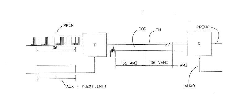
Fig. 1 is a schematic diagram showing the
principles of a data transmission syste~ according to the
invention;
Fig. 2 shows the pulse waveforms of the signals
occurring in the data transmission system of Fi~. 1 for
specific examples of a main or primary and an auxiliary or
secondary bitstream, PRIM and AUX respectively;
Fig. 3a shows a bit order change according to an
aspect of the invention. prior to the application of a
first coding law AMI;
Figs. 3b to 4b show a bit order chanoe according to
an aspect of the invention, using a second coding law VAMI
2 0 ~
J. TOM~AL - P. REUSENS -
D. SAL~AFRTS _ 11-5
and for different values of an indicatioll word INDICWORD;
Fig. 5 5how5 the block structure of a coded symbol
stream COD and the content of the secondary bitstream AUX
in accordance witll the invention;
Fig. 6 shows a schematic diagram of a transmitter T
of Fig. l;
Fig. 7 shows a schematic diagram nf a receiver R of
Fig. l;
The data transmission sYstem del~icted in Fi~. 1
consists of
- a transmitter T ~ith two binary inputs to which two
bitstreams are applied, namely a main or primary
bitstream PRIM of high bitrate and an auxiliary or
secondary bistream AUX nf lower bitrate, the latter
possibly containing multipleKed auxiliary data. The
transmitter T codes the input bitstreams PRIM and AUX
and produces a biPolar (ternary) output signal of
coded symbols COD;
- a transmission medium TM consisting of at least one
ZO electrical wire and possibly including existing HD~3
repeater stations over which the coded symbols COD are
transmitted;
- a receiver R with as input signal the coded symbols
COD, and with as output signals PRIMO and AUXO which
are the reconstructed primary and secondary
bitstreams, P2IM and AUX respectively.
It is to be noted that although the invention is
described using electrical bipolar coded symbols COD and an
electrical wire as transmission medium TM, it is equally
well applicable to other coded symbols and other
transmission media such as optical fibres, wireless
transmission and so on.
The secondary bitstream AUX is depicted in Fig. 1 as
an external input to the transmitter T to better show the
principles of the invention. As already shown in Fig.
2~61 ~ ~ ~
- 12 - J. TOMBAL - P. REUSENS -
D. S_LLAERTS 1~ 5
the secondarY bitstream AUX can however t,e a combination of
an external input bitstream EXT and an intetnal bitstream
INT. The latter bitstream PossiblY containing internal
status information of the transmitter T as well as
particular bits of the primary bitstream PRIM as will be
explained later on. When the secondary bitstream AUX is
thus composed of the above mentioned bitstreams INT and
EXT, as is the case in Fig. 6, only the external bitstream
EXT is applied as a physical input signal, the secondary
bitstream AUX being formed within the transmitter T, which
will be clarified later with reference to Fig. 6. For now
the princiPles of the invention are best understood by
referring to the secondary bitstream AUX as an external
input signal to the transmitter T. Similar remarks hold
for the receiver R depicted in Fig. 7.
According to the invention, the transmitter T
provides for blocks of Y, i.e. 36, bits of PRIM in each of
which a bit of the secondary bitstream AUX, hereafter
called secondary bit, is coded. When a hi~h bitrate of
2û4~ Kbit~sec is available, it can be easily verified that
no integer low bitrate can be found without introducins
blocks of a different length. This point and the exact
composition of a superframe will be clarified further on.
For now we only consider the blocks of 36 bits in which a
secondary bit is coded by s~itching between two coding laws
as shown in Fig. 1 and explained hereafter.
The value of Y is chosen in 5uch a way that during a
complete block of bits of the primary bitstream PRIM,
hereafter called primary bits precisely one secondary bit
3û is present, i.e. to each block Df Y bits of PRIM
corresponds one bit of AUX. From the equality uf the
bitrate of PRIM and the transmis~ion rate it follows that
the coded symbol stream COD can also be divided in blocks
of 36 symbols, each block corresponding uniquely to one
block of primary bits. As is shown in Fig. 1 each of
2 ~
- 13 - J. TOM8AL - P. REUSENS -
- D. SALLAERTS l-11-5
these blocks of primary data is cnded. according to the
value of the corresponding secondary b~t. using a first AMI
or a second VAMI coding law. i.e. when the corresponding
secondary bit equals 0 or l respectively.
To detect the change in coding law some redundancy
available in the coded sYmbols COD ha5 to be exploited. In
accordance with the invention this is done by determining
the second coding law VAMI so as to violate the first
coding law AMI according to a speci1ic violation law. More
particularly this specific embodiment nf the invention
determines the VAMI-law as introducing e~actly one
violation a~ainst the well known AMI-rule in a block of
coded symbols CnD.
The AMI- and VAMI-blocks are depicted as pulse
waveforms in Fig. 2 for a specific example of a block of
primary bits. PRIM. A 1st row of the fi~ure names the
positions pl; ...: p36 within a block of 36 bits or
symbols, a 2nd row identifies the bits of the primary
bitsteam PRIM as bl; ...; b36. In a 3rd row a specific
example of a block of primary bits PRIM ;5 shown. In a 4th
row a corresponding secondarY bit AUX shown for which the
AMI-rule as shown in rows 5 and 6 is selected~ In the 5th
row the primary bits bl; ...; b36 are shown in the order
they will be coded when the AMI-rule is selected for the
Z5 block. The 6th row dePicts the bipolar Pulse waveform
obtained by applying the conventional AMI-rule to the
signal PRIM. The AMI-rule codes binary ones as alternating
~1 and -1 signals called marks M. coding a ~ero as a zero.
In case the secondary bit equals l, as depicted in a 7th
row. and so determines that the block should be VAMI-coded
a bit order before coding is used as shown in an 8th row
and a pulse waveform as in a 9th row is abtained.
As shown in the figure the VAMI~code introduces a
violation V against the AMI-code a~ plO. i.e. the symbol in
plO has the same polarity as the precedin~ mark M in p7.
2 0 ~
- 14 - J 50M~ L - P REUS~NS -
This violation V of the Al11-code can easilY be detected by
the receiver R, which deducts from it the value of the
corresponding secondary bit. How the vinlation i5
inserted, and the reason for inserting it at plO i5
explained later on.
A law determining the above vialation, hereafter
called violation law, is determined in such a way as to
provide for transmission of a secondary bitstream AUX
without increasing the transmission rate above the bitrate
of PRIM and to achieve this without worsening the signal
characteristics of the coded symbol stream COD. In
particular the VAMI-code should be such that the desirable
signal characteristics resulting from the use of the
AMI-code are preserved, i.e. dc romponents should not be
present in the coded symbol stream to avoid unsettlins
receiving amplifiers, and two marks of the same polarity
should not be on neighbouring Positions because this causes
intersymbol interference and misinterpretation in repeater
stations or in the receiver R.
Therefore the violation V is introduced according to
a specific violation law which is realized by means of a
violation word VIOLWORD containing one violation and 4
symbols not violating the AMI-code. These four symbols are
chosen in such a way as to meet the above mentioned
dem3nds. In thi 5 embodiment the word ~MOOV is chosen as
violation word VIOLWORD. The first symbol is a balancing
bit ~ introduced to force subsequent violations V to be of
opposite polarity so that these violations `v do not cause a
dc component in the coded symbol stream. Therefore this
first balancing bit ~ is determined to be a mark M or a
zero according to the polarities of the previous mark M and~
violation V. The appropriate polarities of a are
determined according to the following table:
2~8~
- 15 - J. TOM~AL - P. REUS~NS -
D. SALLAFRTS 1-11-5
B previous M previou 5 V
O + +
+ _
0 _
The two zeroes separate the violation V from any
possible previous mark. which has the same PolaritY. thus
avoiding inter symbol interferenre as mentioned above. The
mark M within the violation word VIOLWORD is chosen to
avoid decoding conflicts in the receiver R as will be
clarified below.
Because the transmission rate i5 fixed to be equal
to the bitrate of PRIM . introducing the violation word
VIOL~QRD inhibits a predetermined number of bits, in this
case 5. of the primary bitstream PRIM to be coded directly
within a block of coded symbols. This problem i5 solved by
indirectly coding 3 predetermined number of bits via the
position VIOLPOS of the violation word VIOLWORD. The
receiver R. in reconstructing both bitstreams, thus not
ZO only has to detect the presence of the violation V but also
the position VIOLPOS of this violation word VIOLWORD within
each block of coded symbols and derive from VIOLPOS the
value of the omitted 5 bits.
This is achieved by storing the value of an
25 indication word INDICWORD at first predetermined positions.
more specifically pl; P2: p3; p4; p5. and discarding the
correspondin~ bits bl;...;b5 of this indication word
INDIC~ORD from the normal data ~low. The transmitter T
then calculates VIOLPOS according to the latter value i.e.
decimal value of INDICWORD at Pl; ...; p5 inoremented with
one gives the position of VIOLWORD within the block of
coded symbols, in Fig. 2 this is p6.
Since bits bl; ...; b5 are omitted for transmission
the transmitter T has to reorder the bits within the block
before they are coded. This coding i5 for the serond
2 ~
- 16 - J. TOM~AL - P. REUSENS -
_. SALLAFRTS_ 1-11-5
coding law VAMI identical to the first coding law AMI
except at the positions of the violation word VIOLWORD. As
proposed in the invention and depicted i~ raws ~ and 9 of
Fis. Z the reordering is achieved by sending the bits, from
b6 onwards, on positions starting from Pl. Once VIOLPOS is
reached the violation word is introduced by the transmitter
T and the replaced bits REPLWORD, e.g. bll: ...; bl5, are
stored. Then the transmitter T codes the following bits,
from bl6 onwards in our example, in sequence inserting
REPLWORD at second predetermined Positions namely
p31;...;p36. REPLWORD is in this waY coded at the end of
the block. Thus a uniquely decodable VAHI-block is formed
in accordance with the invention. The receivsr R reorders
the received symbols inserting INDICWORD at the beginnin~
of the block once it has detected VIOLrOS and calculated
the binary equivalent of VIOLPOS minus 1 which corresponds
to the bits bl;...;b5.
It can be verified that a minimum length of the
blocks has to be provided to carry out this coding scheme
because a number of primary bits INDICWORD equal to the
number of symbols in the violation word VIOLWORD have to be
coded in VIOLPOS. Therefore a block sl-ould be at least
long enough to introduce the violation word VIOLWORD at the
largest possible position VIOLPOS, wl-ich is p32 in our
embodiment, with a violation word VIOLWORD of 5 symbols. Y
has consequently to be at least 36 to leave enough place
for the violation word VIOLWORD to be introduced at
positinn p32. Thus a lower bound exists for Y in choosing
a violation word of a specific number nf symbols and hence
also a hi~her bound for the bitrate of AUX exists in using
a specific violation word.
In Fig. 2 it can also be seen that bits Oll matching
positions in the AMI-block and the VAMI-block carry
different primary data due to the reordering necessary in a
VAMI-block There are no matches between the entries in the
- 2~6~ ~
- 17 - J. TOM~AL - P. REUSENS ~
D. SALLAERTS 1-11-5 _
5th and the ~th rows and these rows indicate which s~ecific
primary bit is directly coded in a specific position within
a block. As a consequence, when due to a transmission
error a violatinn V cannot be interpreted as surh by the
receiver R this amounts to a possible misinterpretation of
every bit in the block affected and hellce to an error
multiplication of on average 36 divided by 2 using the
above reordering scheme for a VAMI-block. According to the
invention this is avoided by also reordering the bits in an
A~I-block before they are coded as is shown more clearly in
Fig. 3a.
Before the primary bits in Fig. 3a are coded via the
AMI-rule theY are reordered by the transmitter T. More
particularly, the bits in the first predetermined positions
pl;...;p5 which are the bits bl;...;b5 itl Fig. 3a are
stored and the following bits, from b6 onwards are coded,
respecting their original sequence, from the first position
onwards inserting the stored bits bl;...;b5 at second
predetermined positions p3Z;...:p36. As is shown in Fig.
3a, for this specific embodiment, this means that the first
five bits are put in the last five positions of the block
before this block is coded.
Looking now at Fig. 3b a VAMI-block is shown where
VIOLPOS is calculated as the first position pl of the
Z5 reordered block and where REPL~ORD consequently contains
bits b6;...;blO which are inserted in the last 5 pusitions
p32;...;p36 of the reordered block. Comparing the final
bit order in Fig. 3a and 3b it can be seen that at least Z6
primary bits are in matching positions thus considerably
reducing the above mentioned error multiplication. In fact
this error multiplicaiton i5 reduced to on average 10
divided by 2, for a violation word of lengl- 5. Other
reordering schemes are possible which result in error
multiplication factors between the above extreme values
mentioned, but the combination of reordering schemes as
- 20~gl~ '
- 18 - J. TOMBAL - P. REUSENS -
D. SALLAERTS l-ll-S
described above results in a minimal error multiplication.
In Fig. 4a and 4b it i5 demonstrated that the above
solution still holds for other values of VIOLPOS according
to different values of INDICWORD. In Fig. 4a bits
5 bl;...;b5 of INDICWORD have value ûlO10 giving as VIOLP~35
10 + 1 = pll and determining REPLWURD as bl6;...;bZO. In
Fig. 4b a specific example is showll where INDICl~lORD is
equal to 11101 giving as VIOLPOS 29 + 1 = p30. It can be
seen that the bits replaced by VIOLWORD give a REPLI~IORD of
10 llariable length because VIOLI~IORD can occupy some of the
second predetermined positions p32;...;p35. When VIO~POS
i5 for instance, determined to be p32 no bits are replaced
and REPLWORD is emptY. In the e~ample of Fig. 4b only b35
and b36 are replaced. REPLWORD consequently contains only
15 two bits and these bits have to be placed at the second
predetermined positions p32;...;p36 insofar as these
positions are not already occupied by VIOLWORD i.e. in this
example REPL~IORD has to be placed in p35 and p36.
From the above it is clear that the block structure
20 of the coded symbol stream COD plays a crucial rul~ in this
data transmission system. The receiver R can only
reconstruct the primary and secondary bitstreams, PRIM and
AUX respectively, by synchronizing on this block structure
and so delineating the blocks. For this purpose a
25 synchronization word SYNCWORD is introduced in the coded
symbol stream COD on a regular basis. In this embodiment
the transmitter T introduces this SYNCWORO, as is shown in
Fig. 5, once every 57 blocks.
In Fig. 5 the predetermined structure of the
30 superframe is shown. It consists of a first block of Z .
more specifically 32, symbols in which the first 8
positions are taken in by SYNCWORD, and 56 blocks of Y,
more specifically 36, symbols in each nf which e~tactly one
secondary bit is coded. In this way and for the e~ample of
35 Fig. 5 with a bitrate of 2048 Kbit~s of PRIM, this
2 ~
- 19 - J. TOM~AL - P. REUSENS -
D. SALLAERTS 1-11-5
superframe structllre is repeated with a l kH~ repetition
rate. The 56 blocks of 36 symbDls provide for the coding
of a secondary bitstream AUX with a bitrate of 56 Kbit~s.
The block of 32 bits is needed to fit exactly 2048 primary
bits in the superframe and to have an inte~er bitrate for
AUX. The transmission rate is according to the invention
2048 KBaud. The SYNC~ORD contains the symbols MBOMOOOV
which cannot be mistaken for any other symbol sequence, and
can hence be detected reliably by the receiver R
synchronizing on the block structure. In this block 8
primary data bits are inhibited from transmission beause
of the introduction of the SYNCWORD. By shifting all the
bits of the primary bitstream PRIM B positions further and
by m~ltiplexing 8 primary bits in the secondary bitstream
AUX they can nevertheless be transmitted without increasing
the transmission rate.
Fig. 5 illustrates this solution in more detail. In
the first block, 24 primary data bits are sent together
with SYNCWORD coding them via the AMI-code without
reordering them within this block. The next 56 blocks are
coded ~ia the procedure described above and 8 primary data
bits are multiplexed at predetermined places in said
secondary bitstream AUX, as shown in Fig. S. The primarY
data bits are taken from the primary bitstream at specific
positions relative to the block in which they are coded as
a secondary bit. In Fig. 5 it is shown that a primary bit
PRIMl is coded in the secondary bitstream AUX in the first
block of Y bits of a superframe. This primary bit PRIMl is
taken as the first bit following the previous block, i.e.
the block of Z bits, and discarded from the primarY
bitstream PRIM before the latter is-coded. Similarly
primary bits PRIM2;...;PRIM8 are multiplexed in tlle
secondary bitstream AUX and coded in dedicated blocks, more
s~ecifically ~; 15;...;50 by taking the bit followin~ the
previous block of Y bits, more specifically 7; 14;...;49.
2 ~ 8 ~
- 20 - J. TOMBAL - P. REUSENS -
D. SALL~FRTS 1-11-5
Thus specific blocks within the superframe are dedicated to
include the 8 primary data positions taken in hy the
SYNCWOR~, e.g. block 1; 8;..~;50. The other blocks within
the superframe carry seconclary bits whicll are the physical
input to the transmitter T and which therefore form the
previously mentioned external bitstream EXT. The
difference between EXT and AUX, and correspondingly hetween
EXTO and AUXO, will be explained in detail with reference
to the functional hardware schemes of the transmitter T of
Fig. 6 and of the receiver R of Fig. 7 respectively. The
receiver R consequently knows which secondary bits belong
to the primary data PRIM.
It is to be noted that the same principle of
dedication of blocks can be used for multiplexing other
types of auxiliary data, e.g. voice and maintenance
signals, and demultiplexing them accordingly in the
receiver R.
A specific example of the bitrates of the bitstreams
depicted in Fig. 5, is given in the following table :
SYNCWORD : 8 Kbit~s directly ) KCaud
PRIM :(2048 Kbit~s -~ 2040 Kbit~s directly
t -~ 8 Kbit~s INT ) -~ 56
t ) KBit~s
AUX :(32 Kbit~s e.g. VOICE - ) 4a Kbit~s )
tl6 Kbit~s e.g. SUPERVISION - ) EXT
The bitrate of 2048 Kbit~sec is transformed in the
transmission rate of 2048 KBaud of bipolar electrical
signals wherein also the secondary bitstream AUX with a
bitrate of 56 Kbit~sec i5 coded, the latter bitstream
cansisting af multiplexed data.
In conventional bipolar electrical data transmission
one further measure is taken to improve the signal
characteristics of the coded symbol stream COD, i.e. long
strings of zeroes are replaced by a special code word
containing a violation. This is neces-.ary because the
receiver R has to be able to recover the clock with which
2~g~
- 2l - J. TOMBAL - P. REUSENS -
D. SALLAERTS 1-11-5
the transmitter T has transmitted the symbols. Long
strings of zeroes cause the receiver to loose its
synchronization with this clock which is clearly
unpermittable. A well known remedy. e.g. as standardi~ed
in CCITT recommendation 6.703, i5 to u~.e after the
AMI-coding a further 11DB3 coding substituting strings of 4
zeroes with 5uc1l a special code word wherein the violation
is used to distinguish and replace the code word at the
receiving end.
A HDB4 tYpe coding law is chosen in this embodiment
as third or signal enhancing coding law, because its
special code word cannot be mistaken for VIOLWORD or
SYNCWORD. It substitutes a string of 5 zeroes with the
special code word LOOOV.
In the special HDB4 code word, L i 5 a second
balancing bit, with the same goal as the previouslY
mentioned first balancing bit B. L i5 determined according
to the following table :
L previ OU5 M previous V
- ~
O _
+ _
Other combinations of violation wnrds, synchronizing
words and third coding laws can be applied, where the third
coding law will be of a HDBX type with X not necessarily
equal to 4. Such a zero substituting law substitutes
strings of X~l zeroes with a special code word of the above
type only containing at most X zeroes and at least one
violation. The combination chosen in this embodiment is
advantageous besause it allows for the reuse of
conventional HDB3 repeater stations as mentioned
previously. The latter fact can be verified by comparing
the signal characteristics of conventional HDB3-AMI signals
and signals obtained using the coding strategy as de-.cribed
- 22 - J. IOMBAL - P. REUSENS -
D SA~LAERTS 1-l
in this application.
With reference to Fig. 6 a ~unctional harclware
scheme is de~cribed for the trans~itter T.
The transmitter T has 2 binary inputs PRIM and EXT
S at which the primary and external bitstreams. PRIM and EXT
respectively are applied. At an output COD of the
transinitter T the bipolar electrical coded sym~ols COD are
provided. The e~ternal bitstream EXT does not include the
earlier mentioned primary bits which are to be multiplexed
~ith EXT within the ~eoondary bitstream AUX. These primary
bits constitute an internal bitstream INT mentioned earlier
~ith respect to Fig. 1. The e~tPrnal bitstream EXT j5
con~equently not equal to the secondary bitstream AUX
applied to the transmitter T in Fig. 1. This ~econdary
bitstream AUX is in fact i~plicitly ~ormed in the
transmitter and wa~ only depicted explicitly in Fio. 1 for
sake o~ clarity. This multiple~ing of primary bits ;5 done
implicitly via a block VAMI-FSM included in T sho~n in Fig.
~.
The bitstream PRIM is applied at an input oP a
~?ariable length buffer VARBUFFER ~hictl has a ma~imum length
of 8 positions. TD be noted that this maximum length
corresponds to the length of SYNCWORD. PRIM j5 also
applied at an input of a multiplexer MUX which has a second
input connected to an output of VARBUFFER. Both MUX and
VAR~?UFFER are controlled by VAMI-FSN.
The output of MUX j5 firstly connected to a shift
register INSERTBUFFER controlled by VAMI-FSM. INSERr~UFFER
has a length equal to that of VIOLWORD? I.e. 5. The output
of MUX is al50 connected to a block INTERNAL 29IT CODING
~hich has a second input connected to the output of
INSERTBUFFER and a third input connected to YAMI-FSM.
INTERNAL 2BIT CODING, controlled by VAMI-FSM, cotles binary
data applied at its inputs in a quaternary internal code
represented in 2 bit notation accordin to that data being
.
2 ~ a S
- 23 - J. TOMSA~ - P. REUSENS -
D. SALLAE _ S l-ll-S _
a 0 ~ M or V. An output of INTERNAL 2BIT CODING i 5
conne&ted tn an input of a shift register HDB4 DETECT which
has a length equal to that of the earlier mentioned 1IDB4
code word. HD~'~ DETECT controls a block named EXTER~IAL
TERNARY CODING to an input of wllich the output si~nal of
HD84 DETECT i 5 applied. EXTERNAL TERNARY CODIN~ codes the
internal quaternary cude generated by IIDB~ DETECT into the
bipolar electrical symbols COD to be transmitted over the
transmission medium TM via the transmitter outPut COD. It
therefore remembers the polarity assigned by it to the
previous mark and violation of the signal generated by HD84
DETECT in flipflops named MFFl and VFF respectively.
The block VAMI-FSM which constitutes the primary
intelligence of the transmitter T. is controlled by an
autput signal of each of three counters Cl to C3 to which
PRIM is supplied. The first counter Cl starts countin~ at
the beginning of the superframe and is reset after the
complete suPerframe of 2048 symbols is completed. It
generates an output signal at the beginning of a
superframe. The counter C2 counts tl-e number of blocks in
the superframe and generates an output signal at the
beginning of each block C2 is also reset after completion
of the superframe. The counter C3 COUIlts the number of
bits in each block and generates at its output the value of
this count C3 i5 reset after completion of each block.
It is to be noted that the above mentioned counters
are connected to PRIM to enable them to count synchronously
with the rate at which the primary bitstream i5 received.
The way in which this i5 done is well known in the art and
therefore not shown.
EXT is connected to VAMI-FSM via a flip-flop EXTFF.
It is to be noted that EXTFF can be so controlled by
VAMI-FSM that it contains the external data relevant at a
particular instance. As this control nperation is strongly
dependent on the various bitstreams to be coded within the
2 ~ 3
- 24 - J. TOMBA- - P. R~USENS -
D. SALLAERTS 1-11-5
secondary bitstream AUX it is not showlt. However when the
e~ternal bitstream EXT has a bitrate equal to 48 Kbit~s the
necessary control can be simply performed by VAMI-FSM which
has to clock the flipflop at the approPriate instance.
Following is with reference to Fig. 6 a description
of the working of the tr3nsmitter.
When the counter Cl indicates by means of its output
sisnal the beginning of a new superframe VAMI-FSM
instructs INTERNAL 2BIT CODING via its control line to
provide at its output the Z bit representation of the
synchronization word SYNC~OR~. As thi 5 requires 8 clock
ticks and the primary bitstream PRIM has to be cuntinuou~ly
prOceS5ed~ a primary bits are via input BRIM shifted in
VARBUFFER and simultaneously the synchrorlization word
SYNCWOQD i5 shifted through HDB4 DETECT and coded in
bipolar signals in EXTERNAL TERNARY CODING. The first 24
primary bits received on PRIM are AMI coded by shifting
them through VARBUFFER with length 8 and sending them from
MUX under the control of VAMI-FSM to INTERNAL 2BIT CODING.
The 2 bit rePresentations of these first 24 bits are then
shifted through HDB4 DETECT and coded in biPolar form in
EXTERNAL TERNARY CODING this block can insert the ~nB4
code word as will be explained later.
The following 56 blocks are coded a5 AMI- or VAMI
blocks dependin~ on the value of the correspondins bit in
the secondary bitstream. Block counter C2 indicates to
VAMI-FSM if this bit is to be taken from PRIM or from
EXTFF i.e. in blocks 1; 8; ... ; 50 the bit is taken from
PRIM Yia VAR8UFFER in order to send 8 primary bits replaced
by SYNCWORD within the superframe as e~plained earlier and
for all other blocks the bits taken from EXTFF. The
multiplexing of these primary bits within AUX is realized
by means of a pointer which at the beginning of the
superframe points at bit 8 of VARBUFFER. Each time a bit
of PRIM has to be taken as secondary bit the bit indicated
2 0 ~
- 25 - J. TOMBAL - P. REUSENS -
D. S_LLAERTS 1-11-5
by the pointer is read by VAMI-FSM and used as secondary
bit correspondin~ to the next block and the pointer is
decremented by 1 bit pO5 i tion until po~.ition O i 5 reached.
From then on PRIM is directly switched via MUX without
using VARBUFFER for further processillg.
According to the value of the corresponding one of
the abnve mentioned bits VAMI-FSM i5 sl~itched to AMI
processing, when that secondarY bit i5 0~ or to VAMI
processing, when that bit is 1.
In AMI processing the output of MIIX is initially,
during the first five bits of each block of Y bits, i.e. on
first predetermined positions pl;...;p5, switched to the
shift register INSERTBUFFER. During these five clock ticks
INTERNAL 2BIT CODING will be busy comPleting the previous
block in determining the last five sYmbols o~ that previous
block which are on this moment stored and have to be
shifted out INSERTBUFFER. From the sixth bit onwards the
output of MUX is directly sent to INTERN~L 2BIT CODING
which codes the incoming bits via the AMI-rule and passes
them to HDB4 DETECT. When counter C3 indicates that the
position 32, i.e. the first of the second predetermined
positions is reached within a block, then the control unit
VAMI-FSM controls INSERTBUFFER to supply its content to
INTERNAL 2BIT CODING which still codes via the AHI-rule,
thus inserting the first five bits of the block at the end
thereof. Meanwhile VAMI-FSrl also enables INSERTBUFFEQ to
receive the first five bits of the next block THROUGH MUX
so completing a cycle.
In VAMI processing the first five bits of a block
which represent the indication word INnICWORD are also
stored in INSERTBUFFER as described in the previous
paragraph. The value of the word in INSERT8UFFER, i.e.
INDICWORD is communicated to VAMI-FSM via the control line
of INSERTBUFFER and when it is equal tn the value provided
by C3, VAMI-FSM instructs INTERNAL 2BIT CODING to ~enerate
2 ~
- 26 - J. TO~lBAL - P. REUSENS -
- D. 5ALLAE_TS ~-11-5
the violation word VIOLWORD and colltrols INSERTBUFFER to
store the following 5 bits passed Dn thrnugh MUX which
represent REPLWORD. When C3 commullicates the 32nd position
to VAMI-FSM or when this position has ~assed whilst
introducing VIOL~IORD, the content of INSERTBUFFER is under
control of VAMI-FSM applied to the input of INTERNAL 2BIT
CODING which codes tllem at the end of the block. Meanwhile
~AMI-FSM also enables INSERT~UFFER to receive the first
five bits of the next block through MUX 50 completing a
cycle.
It is to be noted that the above processing scheme
still holds when C3 has passed 32 whilst VIOL~aRD is
generated. In this case and as was described earlier
REPLWORD has a length shorter than 5. Whilst generating
VIOLWORD in this case not only bits of REPL~ORD but also
the first bits of the next block l~ill he shifted into
INSERTBUFFER. As C2 indicates the beginning of a new block
this does not give rise to extra problems, those bits in
INSERTBUFFER belon~ing to REPL~ORD will be shifted to
INTERNAL 2BIT CODING and with the aid of the counters Cl
and C2 VAMI-FSM can control INSERTBUFFER so as to contain
just the first five bits of the next block.
It is to be noted that INTERNAL 2BIT CODING, except
whilst generating VIOLWORD and SYNCWORD, always codes using
the AMI-rule.
The output signal of I~JTERNAL 2nIT CODING is then
shifted throush HDB4 DETECT and the internal 2 bit code is
further Processed by the block EXTERNAL TERNARY CODING
which generates at its output the bipolar coded signal
stream COD. The block EXTERNAL TERNARY CODING not only
assigns bipolar values according to the previously
mentioned tables and rules but also inserts the special
HDB4 code word whenever it detects via its control line
that HDB4 DETECT contains five zeroes. To supply these
ternary symbols EXTERNAL TERNARY CODING needs to remember
2 ~
- 27 - J. TOMBAL - P. REUSENS -
D. SALLAE~LS l-ll-5
the polarity of the previous mark M an~ violation V in MFFl
and VFF respectively.
Accordins to tlle above functional description, the
realization of the blocks of Fig. 6 is ohvious for a man
skilled in the art and they are therefore not described in
detail.
With reference to Fig. 7 a functinnal hardware
scheme is now describe~ for the receiver R.
R has an input COD where the co~ed symbnl stream COD
is received, and two outputs PRIMO and EXTO where the
primary and the external bitstreams PRIMO and EXTO
respectively are provided. Resarding EXTO and PRIMO the
same remarks can be made as for EXT and PRIM with reqpect
to tle transmitter T of Fig~ 6. The recon~tructed
secondary bitstream AUXO is namely nat shown in Fig. 7
since it is an internal signal in the receiver R. As a
consequence only a part of AUXO, i.e. the reconstructed
external bitstream EXTO, is shown as an explicit out~ut
bitstream. Another part of AUXO is an internal
reconstructed bitstream containing part of PRIMO ahd which
is directly decoded in the receiver R to reconstruct the
primary bitstream PRIMO as described hereafter. The coded
symbol stream COD is applied to an input of a first decoder
EXTERNAL TERNARY TO 2BIT DECODER wllich delivers ternarY
symbols applied to its input in 2 bit representation
according to the received symbol of COD being a mark M, a
zero 0 or a violation V. It therefore has to remember the
polarity of the previously received mark of COD which is
stored by means of a flipflop MFF2 connected to the first
decoder. The output signal of EXTERNAL TERNARY TO 2 BIT
DECODER is applied to an input of a variable length shift
register SYNC-VARBUFFER which is controlled by a control
unit DEVAMI-FSM. An output of SYNC-VARBUFFER constitutes
an input another shift register SCREENING-REG which has a
length equal to the length of VIOLWORD, i.e. 5.
2 ~
- 28 - J. TOMBAL - P REUSENS -
D. SAL_ERT5 1-11-5
SCREENING-REG is connected via a control line to DEVAIII-FSM
and provides output bits wl-ich are applied to an input of a
second decoder INTERNAL 2BIT TO BINARY DECODER. The latter
block decodes the 2 bit representation comin~ frnm
SCREENING-REG into a binary representation according to the
AMI-rule. This representation i5 applied to an input of a
multiplexer MUX2 controlled bY DEVAMI-FSM and to an input
of a shift register SHIFT-REG which is also controlled by
DEVAMI-FSM. MUX2 has a second input to which an out~ut of
the shift register SHIFT-REG, is applied and a third input
to which an output of DEVAMI-FSM is connected. SHIFT-REG
has a length equal to the length of a block of Y bits,
minus the length of VIOEWORD, i.e. 31. MUX2 generates at
its output PRIMO the reconstructed primary bit~tream PRIMO.
R has its primary intelligence in the control unit
DEVAMI-FSM. This unit is controlled by three counters DCl
to DC3 to the input of wl)ich COD is applied.
The first counter DCl counts the symbolq received in
the superframe and ~enerates a control signal to DEVAMI-FSM
ZO at the beginning of the frame. DCl is reset after a
~omplete superframe of 2048 symbols is received. The
counter DC2 counts the number of block~ in the superframe
and provides the value of that count to DEVAMI-FSM. DC2 is
also reset after completion of the superframe. The counter
DC3 counts the number of symbols being received witl1in each
block and provides its count value to nE~AMI-FSM. DC3 is
reset after receipt of a comPlete block. Counters DCl~3
are connected to the input COD of the receiver R. In this
way only they can count tl-e number of incoming coded
symbols COD.
The binary external bitstream EXTO extracted from
the signal COD by DEVAMI-FSM is directly written in a
flipflop EXTFF2. EXTFF2 provides tle signal EXTO at the
output EXTO which can be achieved by aPpropriately clocking
EXTFF2 via DEVAMI-FSM.
2 ~
- Z9 - J. TOM~AL - P. REUSENS -
- D. SAL~AERTS l-ll-S
Following i5 with reference to Fig. 7 a description
of the working of the receiver R wherein the description of
the synchronizatiDn operation of the receiver on SYNCWORD
is omitted as this can be achieved by conventional
synchronizing algorithms.
The first block of 32 symbols of the signal COD is
processed at the beginning of the superframe. This
beginning is indicated to DEVAMI-FSM by DCl. whereafter
DEVAMI-FSM checks whetller the SYNCI~ORD is detected in
SYNC-VARBUFFER at the right moment and updates a
synchronization algorithm accordingly. i.e. when the first
8 symbnls are shifted in SYNC-VARbUFFER after the start of
the new suPerframe a5 indicated bY DCl. If SYNCWORD is
detected bY DEVAMI-FSM it is discarded from the data flow
and a pointer to SYNC-VARBUFFER is reset so that it points
to the beginning of the buffer, i.e. its length is ~ero
meaning that the following symbols are directly passed from
EXTERNAL TERNARY TO ZBIT DECODER to SCREENING-REG. The
following 24 symbols of the first block are via
20 SCREENING-REG passed to INTERNAL 2BIT TO BINARY DECODER to
be decoded via the AMI-rule and are then directly sent in
binary form via MUX2 and under control of DEVAMI-FSM to the
output PRIMO where the primary bitstream PRIMO i5 prnvided.
DEVAMI-FSM then detects whether each of the next 56
blocks are coded using either the VAMI- or AMI-code and
controls their reordering before sending them Yia MUX2 to
the output PRIMO. This detection is done by checkins
whether SCREENING-REG contains VIOLWORC or not.
In the course of shifting a complete block through
SCREENING-REG every combination of 5 consecutive 2 bit
representations is compared by DEVAMI-ESM with the
internally stored 2 bit representation of VIOLWORD. If
VIOLWORD does not appear before the last sYmbol of that
block is shifted in the last position of SCREENING-REG,
that block is interpreted as an AMI-block and the secondary
2 ~
- 30 - J. TOMBAL - P. REUSENS -
D. SALLAERTS 1-11-5
bit corresponding to this block is interpreted as a zero~
If moreover this secondary bit belongs to the external
bitstream as indicated by the number of the block in the
superframe generated by DC2. then it i5 written in EXTFFZ
by DEVAMI-FSM. When VIOLWORD is detected in SCREENING-REG
before the last symbol nf that block is shifted in
SCREENING-REG then that block i5 interpreted as a
VAMI-block and resulting in a binarY 1 for the
corresponding secondary bit.
It is to be noted that SCREENING-REG is also used to
eliminate the special HDB4 code word from the ~ignal
stream. DEVAMI-FSM will namely continuously compare the
content of SCREENING-REG to the internally stored 2 bit
representation of the special code word and when detected
overwrite the content of SCREENING-REG with an all zcroes
word of length 5, i.e. reset SCREENING-REG.
Following is a description of the further Processing
of AMI- and VAMI-blocks without however taking into account
the 8 secondary bits replaced by SYNCWnRD. which have to be
inserted in the primary bitstream PRIMO. This insertion
will be described later.
If the block is detected to be an AMI-block the
content of SCREENING-REG at the end oS that blo~k, as
indicated by DC3. cansists of the 3Znd to 36th symbols of
that block which correspond to the first five symbols o~
the block nf primary bits to appear on the output PRIMO as
explained earlier with respect to the working of the
transmitter T. Under control of DEVAMI-FSM these 5 symbols
are after decoding routed through MUX2 to the output PRIMO.
Hereafter the complete shift register SHIFT-REG is again
under control of DEVAMI-FSM shifted through MUX2 to the
output.
When VIOLWDRD is detected in SCREENING-REG, the
block is a VAMI-block. The value of counter DC3 at the
moment VIOLWORD is detected. decremented by five gives the
2 ~ ~ ~ 1 d ~
- 31 - J. TOMSAL - P. REUSENS -
D. SALLAE TS 1-11-5
value of VIOLPOS from which INDICWORD ancl hence the first
five bits of this VAMI black can be derived. INDIC~ORD i5
temporarily stored in DEYAMI-FSM while the remaining
symbols of the block are decoded in INTERNAL 2BIT TO BINARY
DECODER and shifted in SHIFT-REG. The decoding is always
done via the AMI-rule. When the last ~.ymbol of the
VAMI-block is shifted in SCREENING-REG. the latter shift
register contains REPL~ORD. To provide the reconstructed
primary bitstream PRIMO at the output of MUX2 DEVAMI-FSM
simultaneously shifts the ~tored INDICWORD via a dataline
connecting DEVAMI-FSM to MllXZ to the output PRIMO of the
receiver R and controls SHIFT-REG in 5uch a way that the
bits corresPonding to VIOLWORD in SHIFT-REG are over~ritter
with the bits generated by INTERNAL 2BIT TO BINARY DFCODER
corresponding to REPL~IORD. Whereafter the whole content of
SHIFT-RE~ can be shifted under control of DEVAMI-FSM
through MUX2 to the output PRIMO.
When VIOLWORD occupies one or more of the second
predetermined positions. i.e. of the last five positions.
REPLWORD does not completely occupy SCREENING-REG and
DEVAMI-FSM will accordin~lY have to act SD as to overwrite
less than five bits in SHIFT-REG.
As mentioned earlier the reconstructed secondary
bitstream AUXO is not explicitly shown in Fig. 7 and is
reconstructed by DEVAMI-FSM by interpreting every block of
36 bits as an AMI- or a VAMI-block. The block counter DC2
indicates to DEVAMI-FSM which block is being received
within a superframe and thus indicates to DEVAMI-FSM
whether the secondarY bit correspDnding to that block is
part of the reconstructed primary bitstream PRIMO or of the
reconstructed external bitstream EXTO. When DC2 indicates
that block l; 8;...; 50 is being received DEVAMI-FSM has to
multiplex the secondary bits ccrresponding to these blocks
in the reconstructed Primary bitstream PRIMO as will be
explained in detail in the following paragraph. The other
2 ~ 3 ~
3Z - J TOMBAL - P. REUSENS -
D SALLAERTS 1-11-5
secondary bits are applied via EXTFF2 to the output EXTO of
the receiYer R.
It is to be noted that the principle described in
this paragraph can equally well be uset1 to demultiplex
different bitstreams within the reconstructed extern~l
bitstream EXTO.
As mentioned earlier the secondar~t bits
corresponding to the previously ~entioned blocks 1: ~;...;
50 of the superframe have to be multiplexed within the
reconstructed Primary bitstream PRIMO. This i5 done under
control of DEVAMI-FSM which sends this secondary bit via
the dataline connecting DEVAMI-FSM and MUX2 through MUX2,
before the block in which this secondary bit was coded is
sent through MUX2 to PRIMO. When this bit is passed
through MUX2 no other symbols in 2 bit representatioll or
bit in SHIFT-REG can be shifted towards the output PRIMO
because this would lead to an unsolvable output contention.
Howe~er at tl-e same time a following coded symbol is
received on the input C~D. To avoid input contention
SYNC-VARbUFFER is, as mentioned before, imPlemented as a
variable length buffer. DEVAMI-FSM stores a pointer to
this buffer indicating its lensth, i.e. the pointer
indicates which position of SYNC-VARBUFFER is to be
connected to the input of SCREENING-REG.
After detection of SYNCWORD this POinter is reset,
i.e. set to zero, indicating that the output signal
EXTERNAL TERNARY TO 2BIT DECODER is directly shifted into
SCREENING-REG. At the moment a ~econd~ry bit i5 pas~ed
through MUX2 DEVAMI-FSM increments the POinter to
SYNC-VARBUFFER with unity thereby shifting the 2 bit
representation generated by EXTERNAL TERNARY TO 2 BIT
DECODER of the first symbol of the next block into
SYNC-VARBUFFER. Simultaneously the inPut of SCREENING-REG
is reconnected to the position of SYNC-VARBUFFER as
indicated by the pointer. This procedure is rcpeated for
2 ~
- 33 - J. TOMEAL - P. REUSENS -
D. SALLAFRT~ 1-11-5
all 8 blocks carrying a secnndary bit taken from the
primary bitstream PRIM thereby avoiding input contention.
After the 50th block the pointer has a value of 8
indicating that the complete length of SYNC-VARnUFFER is
used. Thus the receiver R is able at the beginning of a
new superframe to shift the complete 2 bit representation
of SYNCWORD into SYNC-VARBUFFER and update the
synchronization algorithm or begin another cycle as
described in the above.
l~hile the principles of the invention have been
described above in connection with specific ap~aratus, it
i5 to be clearly understood that this description is made
only by way of example and not as a limitation on the scope
of the invention.