Language selection

Search

Patent 2086149 Summary

Third-party information liability

Some of the information on this Web page has been provided by external sources. The Government of Canada is not responsible for the accuracy, reliability or currency of the information supplied by external sources. Users wishing to rely upon this information should consult directly with the source of the information. Content provided by external sources is not subject to official languages, privacy and accessibility requirements.

Claims and Abstract availability

Any discrepancies in the text and image of the Claims and Abstract are due to differing posting times. Text of the Claims and Abstract are posted:

  • At the time the application is open to public inspection;
  • At the time of issue of the patent (grant).
(12) Patent: (11) CA 2086149
(54) English Title: BUILT-IN CHIP TRANSPONDER WITH ANTENNA COIL
(54) French Title: TRANSPONDEUR SUR PUCE INCORPORE A UN CIRCUIT DE BOBINE D'ANTENNE
Status: Deemed expired
Bibliographic Data
(51) International Patent Classification (IPC):
  • H01Q 23/00 (2006.01)
  • G06K 7/08 (2006.01)
  • G06K 19/077 (2006.01)
  • H01Q 7/06 (2006.01)
(72) Inventors :
  • D'HONT, LOEK (Netherlands (Kingdom of the))
(73) Owners :
  • TEXAS INSTRUMENTS INCORPORATED (United States of America)
(71) Applicants :
(74) Agent: KIRBY EADES GALE BAKER
(74) Associate agent:
(45) Issued: 1997-12-23
(22) Filed Date: 1992-12-23
(41) Open to Public Inspection: 1993-07-01
Examination requested: 1993-12-22
Availability of licence: N/A
(25) Language of filing: English

Patent Cooperation Treaty (PCT): No

(30) Application Priority Data:
Application No. Country/Territory Date
91203429.5 European Patent Office (EPO) 1991-12-30

Abstracts

English Abstract


Abstract.

An antenna circuit to be used in conjunction with a chip
transponder such that the antenna circuit serves for both the reception
of interrogative signals intended for the transponder as well as for
response signals that are to be transmitted by the transponder. The
antenna circuit has at least one magnetic circuit of high µ material, and
is formed of ceramic core means, that have been built into a depression
in a thick-walled surface intended to receive the chip transponder. This
thick-walled surface may be of metal. The ceramic core means comprise at
least a ceramic core resonator and half a ceramic core that functions as
an antenna with its open side facing outward. In one aspect, the ceramic
core resonator and the half ceramic core antenna are coupled by means of
one or more secondary coils of the closed ceramic core, which also form
the coils of the half ceramic core antenna. In another aspect, the
secondary coil forms a resonating circuit with at least one capacitive
element in series. In yet another aspect, the ceramic core resonator and
the half ceramic core antenna are formed by one and the same half ceramic
core, which may be closed in part by a magnetic covering disk. In yet
another aspect, the resonator may consist of a half ceramic core which is
placed against the back of the half ceramic core antenna.


French Abstract

DEJA TRADUIT.

Claims

Note: Claims are shown in the official language in which they were submitted.


Claims:
1. An antenna circuit to be used in conjunction with a
chip transponder such that the antenna circuit serves for both
the reception of interrogative signals intended for the
transponder as well as for response signals that are to be
transmitted by the transponder, comprising;
an antenna circuit, having at least one magnetic circuit of
high permeability material, for radiating a magnetic field,
comprising,
ceramic core means comprising at least a ceramic core
resonator and half a ceramic core antenna, having an open side,
which functions as an antenna with its open side facing outward,
wherein said resonator and antenna are mutually coupled, one to
the other, and
wherein the resonator consists of a closed ceramic core, and
wherein the ceramic core resonator and half ceramic core antenna
are coupled by means of at least one secondary coil of the closed
ceramic core, which also form the coils of the half ceramic core
antenna.
2. An antenna circuit to be used in conjunction with a
chip transponder such that the antenna circuit serves for both
the reception of interrogative signals intended for the
transponder as well as for response signals that are to be
transmitted by the transponder, comprising;
an antenna circuit, having at least one magnetic circuit of
high permeability material, for radiating a magnetic field,
comprising,
ceramic core means comprising at least a ceramic core
resonator and half a ceramic core antenna, having an open side,
which functions as an antenna with its open side facing outward,
wherein said resonator and antenna are mutually coupled, one to
the other,
wherein the resonator consists of a closed ceramic core, and
wherein the ceramic core resonator and half ceramic core antenna
are coupled by means of at least one secondary coil of the closed
ceramic core, which also form the coils of the half ceramic core
antenna, and


wherein further said at least one secondary coil forms a
resonating circuit with at least one capacitive element in
series.
3. The antenna circuit in accordance with Claim 2, wherein
the resonant circuit is adjusted, with its frequency on the low
side of the frequency band and the resonator on the high side of
the frequency band.
4. An antenna circuit to be used in conjunction with a
chip transponder such that the antenna circuit serves for both
the reception of interrogative signals intended for the
transponder as well as for response signals that are to be
transmitted by the transponder, comprising;
an antenna circuit, having at least one magnetic circuit of
high permeability material, for radiating a magnetic field,
comprising,
ceramic core means comprising at least a ceramic core
resonator and half a ceramic core antenna, having an open side,
which functions as an antenna with its open side facing outward,
wherein said resonator and antenna are mutually coupled, one to
the other, and
wherein the ceramic core resonator and the half ceramic core
antenna are formed by the same half ceramic core having one or
more coils.
5. An antenna circuit to be used in conjunction with a
chip transponder such that the antenna circuit serves for both
the reception of interrogative signals intended for the
transponder as well as for response signals that are to be
transmitted by the transponder, comprising;
an antenna circuit, having at least one magnetic circuit of
high permeability material, for radiating a magnetic field,
comprising,
ceramic core means comprising at least a ceramic core
resonator and half a ceramic core antenna, having an open side,
which functions as an antenna with its open side facing outward,
wherein said resonator and antenna are mutually coupled, one to
the other,


wherein the ceramic core resonator and the half ceramic core
antenna are formed by the same half ceramic core having one or
more coils, and
wherein further the coils are formed as flat disk-shaped
coils.
6. An antenna circuit to be used in conjunction with a
chip transponder such that the antenna circuit serves for both
the reception of interrogative signals intended for the
transponder as well as for response signals that are to be
transmitted by the transponder, comprising;
an antenna circuit, having at least one magnetic circuit of
high permeability material, for radiating a magnetic field,
comprising,
ceramic core means comprising at least a ceramic core
resonator and half a ceramic core antenna, having an open side,
which functions as an antenna with its open side facing outward,
wherein said resonator and antenna are mutually coupled, one to
the other,
wherein the ceramic core resonator and the half ceramic core
antenna are formed by the same half ceramic core having one or
more coils, and
wherein further said half ceramic core is closed in part by
a magnetic covering disk.
7. An antenna circuit to be used in conjunction with a
chip transponder such that the antenna circuit serves for both
the reception of interrogative signals intended for the
transponder as well as for response signals that are to be
transmitted by the transponder, comprising;
an antenna circuit, having at least one magnetic circuit of
high permeability material, for radiating a magnetic field,
comprising,
ceramic core means comprising at least a ceramic core
resonator and half a ceramic core antenna, having an open side,
which functions as an antenna with its open side facing outward,
wherein said resonator and antenna are mutually coupled, one to
the other, and


wherein the resonator consists of a half of a ceramic core
which is abutting said half ceramic core antenna such that a
portion of the magnetic energy from the resonator is transferred
to the antenna via magnetic coupling.

Description

Note: Descriptions are shown in the official language in which they were submitted.


W16560

B~ilt-in chi~ transponder with antenna c~il

~IELD OF T~E INVENTION
The invention refers to an antenna circuit to be used in a chip
transponder such that the antenna circuit serves both for the reception
of interrogative signals for the transponder as well as for the
dissemination of response signals to be transmitted by the transponder
such that the antenna circuit has at least one magnetic circuit of
material of high ~.
BACKGR~UND OF THE INVENTION
In practice it is known that in order for a transponder chip ko be
embedded in or attached to an object or an animal that is to be
identified. it must be e~uipped with an antenna circuit or antenna
element of high u material. Thus, a chip of this type is often equipped
with a small ferrite staff that serves as an antenna beacon. One
disadvantage is the fact that such an antenna circuit does not have such
a sharply defined field of radiation into space.
Similarly, such an embodiment does not lend itself well to
incorporation into a thick-walled surface.

SUM~qRY OF THE INVENTION
It is the goal of the present invention to create an antenna
circuit for a chip transponder that is to be incorporsted into a thick-
walled surface that does not protrude and is thus little prone to damagefrom the outside due to crushing, one that has an effective field of
radiation while retaining a high quality factor and sufficient selection
difference.
This is achieved in the case of an antenna circuit of the sort
named in the preface that conforms to the inven~ion in such a way that
the antenna circuit is formed of ceramic cores, which are built into a
cavity in a thick-walled surface that is intended for the chip
transponder, so that the field of radiation from the ~ntenna circuit
extends in a direction away ~rom the surface. The surface is, for
example, made of metal.
In this embodiment in keeping with the invention, a damage-
resistant chip transponder that is built into a thick-walled surface and
an antenna circuit are realized which, despite their incorporation into
the metal, yield a high quality factor and adequate antenna properties.


.
- , . .

` ` 2 ~

The selective distance in this case may be. for example, 20 to 30 cm.

BRIEF DESCRIPTION OF THE DRAWINCS
The invention will be illustrated in greater detail by virtue of a
few ex~mples of various embodiments, calling attention to the drawings,
in which:
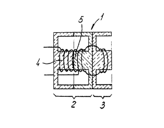
Figures 1 a and 1 b respectively present a transverse section view
and an electrical diagram of the first embodiment in keeping with the
invention;
Figures 2a and 2b respectively present a transverse section view
and electrical diagram of a second embodiment in keeping with the
invention;
Figures 3a, 3b, and 3c respectively present a transverse section
view with a single turn, a transverse section view with the corresponding
structure of a number of coil packets, and an electrical diagram of a
third embodiment in keeping with the invention;
Figures 4a and 4b respectively present a transverse view and an
electrical diagram of a fourth embodiment in keeping with the invention;
Figures 5a, 5b, and 5c respectively present a transverse view, a
frontal view, and an electrical diagram of a fifth embocliment in keeping
with the invention; and
Figure 6 presents a transverse view of a chip transponder built
into a thick-walled metallic surface and the antenna coil thereunto
appertaining.
DF,TAILED DESCRIPTION OF THE INnn~YTION
The incorporation of a chip transponder into a thick-walled
metallic surface and a ceramic core as an antenna entails the problem
that the quality factor which, in open space, may be oO, for example, is
diminished to 60, for example, as a result of being built in. Such
incorporation, therefore, must occur in such a way thht the radiation
field has sufficient scope and selective distance. Preferably, such a
selective distance should be 20 to 30 cm.
This is realized in the embodiments that are illustrated in the
following figures.
Figure la shows a transverse view of an an~enna circuit 1 that
works in conjunction with the chip transponder, which circuit consists of
a ceramic core resonator 2 and a ceramic core antenna 3. The resonator 2
is formed of a closed ceramic core that consists of two half ceramic


,


.: : , , ~ ,
;

6 ~
cores 4. 5, from which a secondary coil (two windings) is connected wi~h
a half of a ceramic core that serves as an antenna. The resonator with
the closed ceramic core ~an, despite the metallic environment, have a
high Q, as a result of which the antenna which has the ceramic core can
have a lower Q. As a result of the aforementioned loose connection, some
energy is used for the radiation field. The quality factor on the
primary side in the resonator remains sufficiently high. In Figure lb,
it is shown that the primary coil in the resonator forms a resonant
circuit with a capacitative element C1 in series. The rPsonator is
connected to the chip transponder 6.
Figure 2a shows a transverse section of a second embodiment. The
secondary circuit is now embodied in such a way as to resonate with a
capacitive element C2. In the equivalent diagra~, which is shown in
Figure 2b, the frequency of the secondary antenna circuit 8 can be
adjusted, for example, to the low side of the frequency band that is to
be used, ~hile the primary resonator 7 is then adjusted to its high side.
In this embodiment, the coupling factor, determined by the number of
coils and the resistor R, is chosen in such a way that a flat band curve
is obtained for the transponder application.
In Figure 3a, a transverse section of a third embodiment is shown,
one with a so-called sliced-inductor packet 10. The resonator and the
antenna are formed by one and the same half ceramic core. This
embodiment has the best antenna properties with good scope of field and
an appropriate selection distance. It is bothersome, however, to retain
a good quality factor in this case. For the purpose of achieving this
end, tinsel conductor, for example, may be used. At the same time,
independent, flat, disk-shaped coil packets, as shown in figure 3b, may
be used as coils in order to keep ~he capacity of the total assembly low,
and, by these means, to retain a hi~h quality ~actor of the resonator.
The equivalent electrical diagram is shown in figure 3c.
In Figure 4a, a transverse section view is presented of a fourth
embodiment in which the resonator 12 that consist~ of having a ceramic
core is placed with its open side against the antenna 13 that consists of
half a ceramic core. In this embodiment, magnetic energy from the
resonator is given off to the cer~mic core antenna by way of the magnetic
coupling. In Figure 4b, once again, th0 equivalent electrical diagram is
indicated.
In Figure 5a, a transverse section view of a further embodiment is
indicated, in which the ceramic core resonator and the ceramic core


.. .
,

: -` 20861~9


antenna are formed once again by one and the same ceramic core 14. This
ceramic core is, in part. shut off on the outside by means of a covering
disk 15, such as Figure 5b indicates. The mechanism is such, in the
meantime, that the resonator's field of distribution is used as the field
of radiation due to the fact that the ceramic core has no ideal closed
magnetic circuit. In Figure 5c. once again, the equivalent electrical
diagram is shown.
In Figure 6. a transverse section view is presented of a
transponder 6 with the appropriate resonator-antenna circuit 17. The
whole is encapsulated in a packaging 18 and incorporated into a thick
metallic wall 16. The antenna circuit may be executed as indicated in
Figures 1 to 5.


' ~ `.,. ' :'
~' :' ~ ',' :


: `` '

Representative Drawing
A single figure which represents the drawing illustrating the invention.
Administrative Status

For a clearer understanding of the status of the application/patent presented on this page, the site Disclaimer , as well as the definitions for Patent , Administrative Status , Maintenance Fee  and Payment History  should be consulted.

Administrative Status

Title Date
Forecasted Issue Date 1997-12-23
(22) Filed 1992-12-23
(41) Open to Public Inspection 1993-07-01
Examination Requested 1993-12-22
(45) Issued 1997-12-23
Deemed Expired 2005-12-23

Abandonment History

There is no abandonment history.

Payment History

Fee Type Anniversary Year Due Date Amount Paid Paid Date
Application Fee $0.00 1992-12-23
Registration of a document - section 124 $0.00 1993-11-05
Maintenance Fee - Application - New Act 2 1994-12-23 $100.00 1994-06-03
Maintenance Fee - Application - New Act 3 1995-12-25 $100.00 1995-06-01
Maintenance Fee - Application - New Act 4 1996-12-23 $100.00 1996-06-13
Maintenance Fee - Application - New Act 5 1997-12-23 $150.00 1997-05-28
Final Fee $300.00 1997-08-12
Maintenance Fee - Patent - New Act 6 1998-12-23 $150.00 1998-06-24
Maintenance Fee - Patent - New Act 7 1999-12-23 $150.00 1999-05-25
Maintenance Fee - Patent - New Act 8 2000-12-25 $150.00 2000-11-03
Maintenance Fee - Patent - New Act 9 2001-12-24 $150.00 2001-11-02
Maintenance Fee - Patent - New Act 10 2002-12-23 $200.00 2002-11-04
Maintenance Fee - Patent - New Act 11 2003-12-23 $200.00 2003-11-05
Owners on Record

Note: Records showing the ownership history in alphabetical order.

Current Owners on Record
TEXAS INSTRUMENTS INCORPORATED
Past Owners on Record
D'HONT, LOEK
Past Owners that do not appear in the "Owners on Record" listing will appear in other documentation within the application.
Documents

To view selected files, please enter reCAPTCHA code :


To view images, click a link in the Document Description column. To download the documents, select one or more checkboxes in the first column and then click the "Download Selected in PDF format (Zip Archive)" or the "Download Selected as Single PDF" button.

List of published and non-published patent-specific documents on the CPD .

If you have any difficulty accessing content, you can call the Client Service Centre at 1-866-997-1936 or send them an e-mail at CIPO Client Service Centre.


Document
Description 
Date
(yyyy-mm-dd) 
Number of pages   Size of Image (KB) 
Cover Page 1994-01-20 1 19
Abstract 1994-01-20 1 35
Claims 1994-01-20 2 64
Description 1994-01-20 4 189
Drawings 1994-01-20 2 54
Description 1997-02-25 5 195
Claims 1997-02-25 4 147
Cover Page 1998-01-06 2 78
Representative Drawing 1998-01-05 1 6
Claims 1998-08-24 4 147
Office Letter 1994-02-21 1 66
PCT Correspondence 1997-08-12 1 58
Office Letter 1996-03-19 1 39
Office Letter 1996-03-04 2 64
Prosecution Correspondence 1993-12-22 1 20
Prosecution Correspondence 1996-04-23 1 47
Examiner Requisition 1995-12-04 1 42
Fees 1996-06-18 1 70
Fees 1995-06-08 2 88
Fees 1994-06-03 1 78