Note: Descriptions are shown in the official language in which they were submitted.
V
TECHNICAL FI~LD:
This invention relates to the field of scanning optical
microscopy and mapping systems, and relates generally to a method
and apparatus for forming a confocal or non-confocal image of a
specimen using transmitted and/or reflected light. The invention
also relates to the fields of fluorescence and photoluminescence
microscopy and mapping.
BAC~GROUND OF T~F INVENTION:
There is a broad class of scanning microscopes and mapping
systems in which a light source is focused to a point on a
specimen, and the light reflected (or emitted) from that point is
measured by a detector. An image of the specimen is recorded by
s~anning the illuminated point across th~ specimen in a raster
scan (scanning beam system), or by moving the specimen in a
raster scan under a stationary beam (scanning stage system).
Scanning stage microscopes are often used when the specimen is
large (for example, when an image is required of a whole
semiconductor wafer).
A simple prior art confocal scanninq stage laser microscope
20 is shown in Figure l. In this implementation the beam from laser
102 is focused by lens 104 onto pinhole 106, and the light
passin~ through pinhole 106 passes through beamsplitter 108 and
is focused by objective lens 110 to a focal spot 111 at the
surface of (or inside~ specimen ~2. For best resolution, focal
2 ,~
spot 111 should be diffraction limited. Light reflected from or
emitted by the specimen at focal spot 111 is collected by
objective lens 110, and part of this light is reflected by
beamsplitter 108 to be focused at detector pinhole 11~. Pinhole
10~ and detector pinhole 11~ are confocal with foca~ spot 111.
Light passing through detector pinhole 11~ is collected by
detector 116. Reflected light from focal spot 111 at specimen
112 passes through detector pinhole 11~, but light from any other
point on the specimen runs into the edges of detector pinhole
11~, and is not collected. This gives the confocal microscope
increased resolution over a non-confocal micros~ope, and since
detector pinhole ~1~ rejects light that does not c~me from the
focal plane, gives the confocal microscope its optical slicing
ability, which allows it to record true three dimensional
images. The microscope shown in Figure 1 uses scanning stages
18 to move the specimen under the stationary laser beam to
record the image, but configurations which scan the beam instead
of scanning the specimen are also known. Microscopes using
infinity-corrected optics are also common, both in scanning-stage
and scanning-beam configurations. These configurations are
described in J. Pawley, "The Handbook of Biological Confocal
Microscopy", IMR Press, Madison WI 53706 (1989~. In addition, it
i8 known that detector pinhole 11~ and detector 116 behind it
(which together comprise a confocal detector) can be replaced
with a small detector whose area is the same as that of detector
pinhole 11~.
Scanning stage microscopes have several disadvantages over
scanninq beam microscopes. The main disadvantage is the
increased time required to acquire an image, because scanning the
specimen undèr a fixed beam is inherently slower than scanning
the beam. Rapid scanning of the specimen and stages can also
cause vibrations in the microscope andlor in the specimen itself
which can cause blurring in the acquired image, an additional
disadvantaqe. One advantage of scanning stage microscopes is
3 i~
their ability to perform very large scans with high spatial
resolution. One example of such an application is the use of a
non-confocal scanning stage microscope for photoluminescence
mapping of semiconductor wafers as described by Moore et al, "A
Spatially Resolved Spectrally Resolved Photoluminescence Mapping
System", Journal of Crystal Growth 103, 21-27 (1990~. When
scanning optical microscopes are used with large specimens like
semiconductor wafers, they are often referred to as "mapping
systems" or "mappers".
A prior-art infinity-corrected scanning beam confocal
microscope is shown in perspective in Figur~ 2. Light beam 203
from light source 202 is focused on pinhole 206 by lens 206. The
expanding beam exiting pinhole 208 is focused to a parallel beam
by lens 210. (Lens 206, pinhole 208 and lens 210 constitute a
spatial filter and beam expander.) The parallel beam passes
through beamsplitter 212 and is deflected in the x-y plane by
first scanning mirror 21~, which rotates about an axis parallel
to the z-direction. Lenses 216 and 218 of focal length f2 return
the deflected light beam to the center of second scanning mirror
20 220, which rotates about an axis parallel to the x-direction and
imparts a deflection in the y-z plane. Lenses 222 and 224 of
focal length f3 return the deflected beam (which now has been
deflected by ~oth scanning mirrors) to enter objective lens 226
centered on its entrance pupil. Objective lens 226 focuses the
light to a focal spot 227 (which for best resolution should be a
diffraction-~imited spot) at the surface of or inside specimen
228. The focus position is set by focus stage 230, which moves
in the z-direction. Light reflected back from or emitted by the
tlny volume of the specimen at focal spot 227 is collected by
objective lens 226 and passes back through the scan system of the
microscope. Part of this returning beam is reflected by beam-
splitter 212 towards lens 232. Lens 232 focuses the light onto
detector pinhole 23~. Light originating from focal spot 227 in
specimen 228 passes through detector pinhole 234 and is detected
~y detector 236, light from any other point in specimen 728 hits
the metal edges around detector pinhole 23~, and is not detected.
As the scanning mirrors 214 and 220 move focal spot 227 across
specimen 22B, an ima~e is recorded of features of the specimen
that are in the focal plane of objective lens 226. If the
specimen position is changed by moving it toward or away from the
objective lens, an image from a different slice through the
specimen is recorded.
Several other prior art embodiments of the scanning beam
confocal reflected light microscope exist, including microscopes
uGing a single mirror that can be scanned about two perpendicular
axes, and microscopes using acousto-optic deflectors as described
by Pieter Houpt et al in US Patent #4,86~,226.
Another prior art embodiment of a confocal scanning-beam
laser microscope uses an acousto-optic deflector to scan the beam
in the fast scan direction and a scanning mirror to scan it in
the slow scan direction. In this embodiment, the reflected or
fluorescence light returning from the specimen is descanned by
the mirror in the slow scan direction, and is then reflected
toward a confocal detector comprising a linear detector array so
no descanning is required in the fast direction. This has the
advantage of al~owing very high speed scans without having to
pass the reflected or fluorescence light back ~hrough the
acousto-optic deflector, which would considerably reduce the
intensity of the light reachinq the detector.
Yet another prior-art embodiment of a confocal scanning-beam
optical microscope is the class of microscopes known as Nipkow
Disk microscopes. The microscopes in this class were described
by Gordon Kino in "Efficiency in Nipkow Disk Microscopes", in
"The Handbook of Bioloqical Confocal Microscopy", p.s3-ss (IMR
Press, Madison, WI 53706, edited by J. Pawley). These
microscopes are different from the microscopes already described
mainly in that a large number of incoming scanniny beams are
, j ~
focused on the specimen simultaneously, and reflected or
fluorescent light beams from these focused spots are detected
simultaneously.
Scanning beam microscopes that are not infinity corrected
have also been made. All of these microscope~ are often used
for fluorescence measurements (see J. Pawley, referred to
earlier).
A prior art scanning stage reflection and transmission
confocal microscope is shown in Figure 3. In thi~ microscope
transmitted light is collected by a second objective lens 320
placed beneath specimen 112, confocal with the first objective
lens 110. Transmitted light from the focal point is collected by
second objective lens 320, passes through pinhole 322 in front of
transmitted-light detector 32~, whereas light from other points
in specimen 112 hits the edges of pinhole 322 and does not reach
detector 32~. The sample is translated in a raster scan relative
to the fixed beam. Thus this microscope performs optical image
slicing in transmission as well as in reflection. A scanning
stage transmission confocal microscope was described by G.J.
Brakenhoff, "Imaging Modes in Confocal Scanning Light
Nicroscopy", Journal o~ Microsc~py 117, 233-242 (1979).
The scanning stage transmission microscope shown in Figure 3
has all of the disadvantages of scanning stage microscopes listed
earlier, but this microscope has the advantage of being able to
form images in transmission. One disadvantage is that the
recolution of both reflection and transmission images becomes
progressively poorer as the microscope is focused further beneath
the top surface of the specimen. This is caused by spherical
abberation in the specimen.
Scanning beam transmission confocal microscopes have been
thought to be impractical ~see D. Goodman, "Confocal Microscopy",
note~ from a course at SPIE's 1989 Symposium on Microlithography,
6 ~ J; ~
San Jose, CA (1989)), since they require precise synchronization
of two scan systems, one in the source arm of the microscope, and
one in the detector arm, so the source pinhole and detector
pinhole are imaged at the same point on the specimen as the scan
proceeds. However, one design of a transmission scanning beam
microscope has been described in the literature by S. Goldstein,
"A No-Moving-Parts Video Rate Laser Beam Scanning Type 2 Confocal
Reflected/Transmission Microscope", Journal of Microscopy 53,
RPl-RP2 (1989) and in US Patent #4,827,125. Goldstein does not
descan the transmitted beam; instead his invention uses an Image
Dissector Tube to scan the detector pinhole in synchronism with
the scanning transmitted (or reflected) beam. Precise
synchronization is difficult and requires sophisticated
electronics, and different optical paths must be used for
reflected-light and transmitted-light imaging, requiring two
complete detector systems. The only practical detector that has
been used in this microscope is the image dissector tube,
severely limiting the choice of detectors for different
applications.
The prior art confocal scanning beam microscopes described
herein and in the reference literature are used generally for
reflected-light and fluorescence or photoluminescence imaging.
These microscopës have several limitations. First, the image-
slicing ability of these confocal microscopes enables them to
record three-dimensional images, but viewed from one side of the
specimen only. Second, when scanning specimens more than a few
micronR thick, spherical abberation degrades the image as the
beam penetrates deeper into the specimen, and the degradation
increases with depth. This i5 true for both reflected-light and
fluorescence or photoluminescence imaging. Third, biological
specimens are often only weak reflectors, requiring either high
levels of illumination or frame averaging to build up an image.
~ourth, when fluorescence or photoluminescence measurements are
performed using these microscopes, the focus of the microscope
may be at a slightly different position for the incoming
illumination than it is for the photoluminescence or fluorescence
wavelengths emitted by the specimen, since photoluminescence or
fluorescence occurs at wavelengths that are different from the
exciting wavelength, and the focal length of a microscope
objective varies slightly with wavelength.
It is an object of the present invention to provide a
practical scanning beam confocal microscope that will record
confocal images in both transmission and reflection.
It is another o~ject of this invention to provide confo~al
images from both sides of a specimen, in both transmission and
reflection, which allows the operator to form a reflected-light
image of both the top and bottom of an opaque specimen, thus
allowing the microscope to additionally record the bottom half of
a three-dimensional image of an opaque specimen. In addition,
this can reduce the effect of spherical abberation by allowing
the operator to illuminate the specimen with a beam that impinges
on the specimen from the side closest to the focal plane. Thus,
a beam from the top can be chosen when imaging the top half of a
specimen, and one from the bottom when imaging the bottom half.
It is yet a f~rther object of this invention to provide a
scanning-beam confocal photoluminescence or fluorescence
microscope in which the incoming illumination is focused by one
objective lens and the fluorescence or photoluminescence emitted
by the specimen is collected by the second objective lens, which
now can be placed at the proper focal distance to collect light
at the fluorescence or photoluminescence wavelength emitted from
the illuminated spot in the specimen.
It is yet a further object of this invention to provide a
confocal scanning beam laser microscope or mapping system, that
allows the operator to choose any of four operating modes for the
microscope: tranRmission with illumination from the top of the
specimen, transmission with illumination from the bottom of the
specimen, reflection from the top, and reflection from the
bottom, in addition to being able to use the microscope for
fluorescence or photoluminescence imaging.
It is a further object of this invention to provide a
confocal scanning stage microscope, or one using a scanning stage
in one direction and a scanning beam in the other, that will
provide any of the capabilities described in the objects stated
above.
BRI~F DE~CRIPTIO~ OF TH~ DRA~ING8:
Figure 1 is a simplified side view of a scanning stage
confocal reflection microscope of the prior art.
Figure 2 is a simplified perspective view of an infinity-
corrected scanning beam confocal laser reflection microscope ofthe prior art.
Figure 3 is a simplified side view of a confocal scanning
stage reflec~ionltransmission microscope of the prior art.
Figure ~ is a simplified side view of one embodiment of the
present invention, an infinity-corrected confocal scanning stage
reflection and transmission optical microscope.
Figure 5 is a simplified side view of another embodiment of
the present invention, a non-infinity-corrected con~ocal scanning
stage reflection and transmission microscope.
Figure 6 is a simplified side view of a further embodiment
of the present invention, an infinity-corrected scanning optical
transmission and reflection microscope in which analyzers are
used to select separately each of four imaging modes of the
microscope.
Figure 7 iB a simplified side view of one embodiment of the
objective lens and transmission arm assembly of an infinity-
corrected confocal ~canning beam laser transmission and
reflection microscope.
~igure ~ is a simplified perspective view of the preferred
2~ embodiment of the present invention, an infinity-corrected
confocal scanning beam optical transmission and reflection
microscope.
tO
Figure 9 is a simplified side view of one embodiment of the
objective lens and transmission arm assembly of a non-infinity-
corrected confocal scanning beam optical transmission and
reflection microscope.
~ n~
DEBCRIPTION OF T~E INVENTION:
The present invention is a practical confocal scanning
microscope that can be used for reflected-light and transmitted-
light imaging and for fluorescence or photoluminescence imaging.
Both scanning stage and scanning beam versions will be
described.
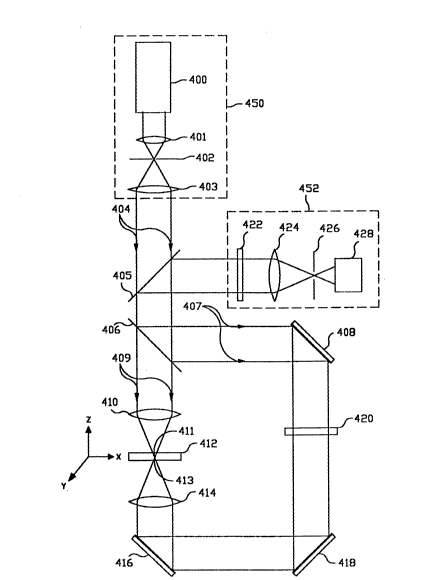
Figure 4 ~hows one embodiment of the invention, a
transmitted-light and reflected-light confocal microscope using a
pair of scanning stages to move the specimen in a raster scan in
x and y directions under the stationary laser beam. A third
stage moves the specimen in the z (axial) direction to change the
focus position with respect to the specimen. (These stages are
not shown in the diagram and this arrangement of scanning stages
and focusing stage is known in the art). In this embodiment of
the invention, incoming parallel light beam ~0~ of polarized
light (from light source ~50 comprising laser ~00 (or other
polarized light source) and spatial filter comprised of lens 401,
pinhole 402 and lens ~03) passes through first beamsplitter ~05
and impinges on the second beamsplitter ~06. (Part of the light
beam, reflected to the left by first beamsplitter ~05, is lost).
At second beamsplitter ~06, part of the the light beam (light
beam ~07) is reflected toward mirror ~OB and part is transmitted
(light beam 409) toward flrst objective lens ~10.
Light beam ~09 entering first objective lens ~10 is focused
to a f~cai spot 411 at the focal point of that lens at the
surfaca of, or inside, specimen 412. Light transmitted through
the specimen i~ collected by second objective lens 41~ (whose
focal spot ~13 is at the same position as focal spot ~11 of first
objective len~ ~10), is reflected through 90 degrees by mirror
~16 and through 90 degrees by mirror ~18, passes through half-
wave plate ~20, which rotates the polarization of the light beam
by 90 degrees, is reflected through 90 degrees by mirror ~08 and
12 ~ ~
partially reflected by beamsplitter ~0~ toward beamsplitter 405.
It is then partially reflected by beamsplitter 405 and enters the
detection arm 452 of the microscope. It then passes through
analyzer ~22 and is focused by lens ~2~ to pass throuqh detector
pinhole ~26 to reach detector ~28. Detector pinhole ~26 is
confocal with the focal spot of the two objective lenses 410 and
~14, and rejects light coming from all points in specimen 412
other than the coincident focal spots ~11 and 413 of objective
lenses ~10 and 41~.
]C~ Light reflected by beamsplitter ~06 toward mirror 408 (light
beam 407) is reflected through 90 degrees by mirror ~08, passes
through half-wave plate 420 where its polarization is rotated by
90 degrees, is reflected through 90 degrees by mirror ~18 and
through a further 90 degrees by mirror ~16, and is focused to
~ocal spot ~13 (coincident with focal spot ~11) by objective lens
41~. Light transmitted upward through specimen ~12 is collected
by objective lens 410, then is partially reflected and partially
transmitted by beamsplitter ~06 (the part reflected to the left
i8 lost). The transmitted portion travels back up the
microscope, and is partially reflected by beamsplitter ~05 to
enter detection arm ~52. The other part of the light beam is
transmitted through beamsplitter 405 and is lost. In detection
arm 452 the light beam passes through analyzer ~22, and is
focused by lens ~24 to pass through pinhole ~26 to reach detector
~Z8. Note that both light beam ~09, which is transmitted through
specimen ~12 from above, and light beam 407, which is transmitted
through specimen 412 from below, pass through half-wave plate ~20
once before reaching detection arm ~52, and have the same
polarization as they enter analyzer 422.
At the same time, light reflected by specimen 412 also
travels back to detector ~28. When light beam 409 impinges on
specimen ~12 from above, light reflected by specimen ~12 is
collected by objective lens ~10, and travels as a parallel light
beam back to beamsplitter ~05, where it is partially reflected to
13 ;~ r J .`
enter detection arm ~52. Light beam ~07 passes through half-
wave plate ~20 before entering specimen 412 from below, and light
reflected from specimen ~12 passes back through half-wave plate
~20 again on its way back to detection arm ~52. Thus the part of
light beam ~07 reflected back from specimen 412 passed through
half-wave plate ~20 twice as it traveled through the microscope,
so it has the same polarization as the reflected-light portion of
light beam ~09 when the two beams enter detection arm ~52, but is
polarized at 90 degrees to the polarization of the two
transmitted-light beams when they enter detection arm 452.
Analyzer ~22 can be rotated to select either light transmitted by
specimen ~12 or light reflected from specimen 412. Since the
~est resolution iB achieved when focal spots ~11 and 413 are as
small as possible, a good choice for objective lenses ~10 and ~14
is a pair of identical high quality infinity-corrected microscope
objectives. The optical assembly comprising second objective
lens ~1~, mirrors ~16, 41~, and ~OB, beamsplitter ~06 and half-
wave plate ~20 is called the transmission arm of the microscope.
When the specimen thickness changes, the relative positions
of objective lenses ~10 and ~1~ must be changed slightly so they
will remain confocal. This can be accomplished by moving
objective lens ~1~ up or down while observing the signal from
detector ~28 with analyzer 422 set to select transmitted light.
There will be a ma~imum in the detected signal when objective
lenses ~10 and ~1~ are confocal.
This microscope has several advantages over the prior art.
By rotating analyzer ~22, either reflected or transmitted light
can be detected by the same detector. ~n addition, the
microscope detects light reflected from both the top and bottom
30 of a specimen, thus forming a confocal image which contains
reflected~ ht i~formation from both the top and bottom of the
specimen.
The microscope can also be used for fluorescence or
14 ~ r
photoluminescence imaging, which does not require a polarized
light source. One possible implementation would be to replace
beamsplitter ~05 with a dichroic beamsplitter that transmits the
source wavelength, but reflects the longer fluorescence or
photoluminescence wavelengths. In this implementation,
fluorescent or photoluminescent light from specimen ~12 is
reflected by beamsplitter 405 to enter the detection arm 452.
Since the fluorescent or photoluminescent light is not polarized,
analyzer 42~ can be removed. All of the photoluminescence or
fluorescence wavelengths would then be detected simultaneously.
Spectrally-resolved detection systems can be implemented if
measurement of a complete spectrum is required.
A second possible implementation of the microscope for
fluorescence or photoluminescence imaging can be accomplished by
replacing beamsplitter ~06 with a dichroic beamsplitter. If a
dichroic beamsplitter is chosen that transmits the source
wavelength and reflects the longer fluorescence or
photoluminescence wavelengths, then second objective lens 41~ can
be focused at the proper distance to collect light at the longer
fluorescence or photoluminescence wavelength of interest, while
first objective lens ~10 is focused at the correct distance for
the source wavelength. In this embodiment liqht goes around the
transmission arm in only one direction. This method can also be
used with the scanning beam embodiments described later.
An additional embodiment of the invention is shown in Figure
5, where a similar transmission arm is implemented in a non-
infinity-corrected microscope. In this particular embodiment,
lenses 518 and 526 are chosen to provide parallel beams for the
opt~cal components (mirror S20, analyzer 522, and mirror 524)
30 that steer the beams around the specimen. Beamsplitter 509
performs the same function as beamsplitter ~06 in the microscope
described in Figure 4, and beamsplitter 5V8 directs light
returning from the sample into the detection arm of the
micrcscope. In this embodiment an additional lens is not
o t ~
S ~
required to focus the returning bea~ onto pinhole 530.
A further embodiment of the invention is shown in Figure 6.
This embodiment is the same as that shown in Figure 4, with the
addition of analyzer 630, which is shown just below
half-wave plate ~20 (several other positions are possible). If
analyzer C30 hae its polari~ation axis parallel to that of the
original polarized light beam ~0~ entering the microscope, then
light beam ~09 after transmission through specimen ~12 passes
through analyzer 630, has its polari2ation rotated 90 degrees by
half-wave plate ~20, and continues through the microscope to
enter detection arm ~52. At the same time, light beam ~07 which
i8 traveling clockwise around the transmission arm 650 has its
polarization rotated 90 degrees by half-wave plate ~20 before it
reaches analyzer 630, and light beam 407 is not transmitted by
analyzer 630. Analyzer ~22 can then be used to select either
transmitted light that enters specimen 412 from above, or light
reflected from the top of specimen ~12. If analyzer 630 is now
rotated so that its polarization axis is perpendicular to that of
light beam ~0~ entering the microscope, analyzer ~22 then selects
transmitted light that entered specimen ~12 from below. When
analyzer ~22 is then rotated by 90 degrees, it selects reflected
light from both sides of specimen ~12. If a third analyzer 632
i5 placed just above objective lens ~10 with its polarization
axis perpendicular to that of incoming light beam 404, it stops
light beam ~09 from entering objective lens ~10, and thus stops
the reflected-light signal from above, without interfering with
either the transmitted-light or reflected-light signals
originating from light bea~ ~07 that entered specimen 412 from
below. The additional advantage of the embodiment described in
this paragraph is that it allows each of the four returning beams
to be detected separately, whereas in the previous embodiments,
either both reflected beams or both transmitted beams reached
detector ~2~ at the same time, and interference effects could
change the measured image. By comparing results from the single
3S beam case (as just described) and the two-~eam case with
~ t
16 f~
analyzers 630 and 632 removed, the interference effects can be
determined, and this may be a useful contrast mechanism. In
addition, this allows the operator to choose a beam from the top
when imaging the top half of the specimen, or a beam from the
bottom when imaging the bottom half of the specimen, thereby
reducing the effect of spherical abberation on the image.
The techniques described above to make a scanning stage
transmission and reflection laser microscope can be extended to
make a scanning beam system. Here the challenge is to design an
optical system that divides the incoming laser beam into two
parts just before it enters objective lens 226 of Figure 2, and
steers one part of the incoming beam around the specimen to enter
a second objective lens below the specimen at exactly the correct
angle so that the focal spots from the two lenses remain
coincident a~ the scan proceeds. In addition, it must be
possible to move the two objective lenses closer together or
farther apart to compensate for the change of optical path length
with sample thickness. One embodiment of such a beam-steering
arrangement (or transmission arm) is shown in Figure 7. In this
diagram, lenses 224 and 226 denote the same lenses as they did in
Figure 2. In Figure 7, dashed lines represent a beam above the
plane of the diagram, and dotted lines represent a beam that is
below the plane of the diagram. The light beam 700 has already
passed through the scan system of the microscope shown in Figure
2, and is shown in Figure 7 approaching lens 226 as a parallel
beam (light beam 701) that is below the plane of the diagram and
to the right of optic axis 703 (solid line), and is traveling
upward toward the plane of the diagram and to the left to enter
first objective lens 226 just as light beam 700 crvsses optic
30 axis 703. Objective lens 226 focuses this incoming parallel
beam to a focal spot 705 at the position of specimen 228. Part
of incoming light beam 700 is reflected by beamsplitter 702
(light beam 70~) toward mirror 706, and passes through the optic
axis at A, a distance of f3 from lens 224, measured along the
35 optic axis On the diagram, the dots bec~me dashes at this
17 ~n~
position. The beam is then reflected by mirror 706 toward lens
708. The lenses 708 and 710 have the same focal length (f4);
lens 708 is placed a distance equal to its focal length (f4) from
the point A where the beam crossed the optic axis, and a distance
equal to twice its focal length from lens 710, which is a
distance equal to its focal length (f4) in front of second
objective lens 712. All of these distances are measured along
the optic axis 703 of the transmission arm of the microscope.
After the beam passes through lens 708, it passes through half-
wave plate 71~ which rotates its polarization by 90 degrees. Itis then reflected toward lens 710 by mirror 716. Lens 710
converts the diverginq beam into a parallel beam and bends it
toward the optic axis. It then passes throu~h roof prism 718
which reflects the beam towards second objective lens 712 and
~lso reverts the beam (moving it from above the plane of the
diagram to below the plane). It enters second objective lens 712
at the axis, and is focused by objective lens 712 to exactly the
same focal point 705 in specimen 22~ as the focal point of the
beam entering specimen 228 from the top, cominq through objective
lens 2~6. The total optical path length alon~ the axis, measured
from the position of lens 22~ to second objective lens 712 around
the transmission arm is f3~f4~2f4+f4=f3+4f4. Other optical
arrangements are possible. For example, the position of roof
prism 718 can be exchanged with the position of either mirror 706
25 or mirror 716. Also, other combinations of optical elements are
pos~ible. For example, if roof prism 71~ is replaced by a mirror
at the same position, a reversion prism can be placed in the
tran~mission arm to revert the beam. One possible position for
the reversion prism is between mirror 716 and half-wave plate
30 714. The focal length of lens 708 and lens 710 is chosen to
provide enough distance around the beam-steering arm for
placement of optical components, and to allow axial focus
adjustment of second objective lens 712 to allow for different
specimen thicknesses. If objective lens 712 is moved to chanqe
3~ focus, the other components in the transmission arm must be moved
in such a way as to maintain the distances between second
18 ~ J `' -
objective lens 712 and lens 710, lens 7~0 and lens 708, and lens
708 and objective lens 226, measured along the axis. In this
embodiment, the specimen is mounted on a stage (not shown) that
can be moved in the focus direction (toward or away from
objective lens 226) after each raster scan is complete, in order
to change the scan plane in the specimen.
Figure 8 shows the preferred embodiment of the
transmission/ref~ection confocal microscope incorporating the
transmission arm described in Figure 7. If light source 202 is
polarized, analyzer 80~ when combined with half-wave plate 71~
allows the operator to select light traveling either clockwise or
counterclockwise around the transmission arm, and when used in
con~unction with analyzer 802 at the entrance of the detection
arm in front of the detector and analyzer 806 above objective
lens 22C, any of four imaging modes can be selected separately,
exactly as described for the scanning-stage embodiment shown in
Figure 6. If analyzer 806 and analyzer 80~ are both rotated so
their polarization direction is parallel to the polarization of
the incoming light beam, then analyzer B02 passes light reflected
from the top of specimen 228 when it's polarization is parallel
to the polarization of the light beam, and it passes light
transmitted from top to bottom through specimen 228 (in the
direction from lens 226 toward lens 712) when it's polarization
i6 perpendicular to that of the incoming light beam. If the
25 polarization directions of analyzer 806 and analyzer 804 are both
rotated by 90 degree~ (to a position perpendicular to the
polarization of the incoming light beam) then analyzer 802 can be
used to select either light reflected from the bottom of specimen
228 or light transmitted upwards through specimen 228 (in the
30 direction from lens 712 towards lens 226).
Many other optical combinations are possible. For example,
if the microscope of Figure 8 will be used only in a reflection
mode, then analyzers 802, B0~, and 80~ and half-wave plate 71~
can be removed~ Then reflection from the top can be chosen by
19 " t ,^"` ~,~ r ~
blocking off the beam traveling from beamsplitter 702 toward
mirror 706, or reflection from the bottom can be chosen by
blocking off the beam traveling from beamsplitter 702 towards
objective lens 226.
The transmission arm shown in Figure 7 is designed for an
infinity-corrected scanning beam microscope, and must be changed
to suit a non-infinity-corrected scanning beam microscope. one
embodiment of the transmission arm for a non-infinity-corrected
scanning beam transmitted-light and reflected-light confocal
microscope is shown in Figure 9. In a non-infinity-corrected
confocal scanning optical microscope, the polarized light beam
902 has already passed through the microscope scan optics (not
shownl, and approaches objective lens 90~ expanding from a point
above the objective lens. Beamsplitter 906 is inserted above
ob;ective lens 90~ to reflect part of the incoming beam into the
transmission arm that will steer the beam around specimen 907 to
enter a second objective lens 908 which is identical to and
confocal with objective lens 904. The lens 910 is inserted into
the expanding partially-reflected beam before it has expanded to
the diameter it will reach when entering second objective lens
908. The foc~l length of lens 910 is chosen to collimate the
expanding beam. The collimated beam passes through the beam-
steering optics as before, and passes through negative lens 92~,
which has the same (but negative) focal length as lens 910.
Negative lens 92~ i8 placed a distance d in front of objective
lens 90~ 50 the expanding beam entering second objective lens 908
has the came diameter as that entering objective lens 9o~. Both
objective lenses 90~ and 908 are focused at the same focal spot
905 inside specimen 907. If this transmission arm iq used to
30 enable transmitted-light imaging in a Nipkow Disk microscope,
half-wave plate 916 should be removed, since some versions of
these microscope~ use a half-wave plate to reduce reflections in
the optical sy~tem.
From the foregoing description it will be appreciated that
the invention makes available a scanning optical transmission and
reflection microscope with many advantages over the prior art.
These advantages were listed as a series of objects of the
invention. All of the objects have been achieved. An additional
advantage is that all the images from the different imaging modes
of the microscope are in perfect registration.