Note: Descriptions are shown in the official language in which they were submitted.
2086374
BP File No. 5562~73
Title: RELEASE MECHANISM FOR USE WITH
A VACUUM CLEANING HOSE
5 FIELD OF THE INVENTION
This invention relates to a device for use with a vacuum
cleaning hose and pipe arrangement. More particularly, the device is a
release mechanism for engaging and disengaging a pipe slidably
mounted inside a flexible hose.
BACKGROUND OF THE INVENTION
Vacuum cleaners in use today typically are of the upright
variety or the horizontal variety. The horizontal vacuum cleaners
comprise a canister and vacuum chamber which is coupled to a
15 cleaning attachment by a flexible hose. The cleaning attachment is
pushed and pulled over the surface to be cleaned. In upright vacuum
cleaners, the cleaning head and vacuum chamber are integrated as one
unit. The upright vacuum includes a handle for pushing and pulling
the vacuum over the surface to be cleaned.
To provide additional flexibility of operation, some
upright vacuum cleaners are convertible. Such vacuum cleaners have
a handle which comprises a flexible hose and rigid wand combination.
The rigid wand slidably fits inside the flexible hose. In normal upright
operation, the wand is locked to the vacuum chamber and provides a
25 rigid handle for pushing and pulling the vacuum in the upright
mode. To provide an easy handling vacuum attachment, the wand is
disengageable from the vacuum chamber and a vacuum nozzle canbe
attached to the one end of the wand, for example to clean drapes. The
wand and flexible hose arrangement can now be used in much the
30 same manner as for a horizontal vacuum.
It will be appreciated that in some situations, the person
using the vacuum appliance will want to remove the wand and just
20~6374
-3 -
use the vacuum nozzle attached to the flexible hose. A known release
mechanism comprises a cuff attached to the end of the flexible hose.
The cuff keeps the wand in place by a friction fit. To detach the wand
from the hose requires pulling or tugging the wand through the
5 constriction of the cuff. While providing a secure attachment this
arrangement suffers two principle drawbacks. First, it is clearly
inconvenient to tug the wand through the constriction of the cuff.
Secondly, and more importantly, repeated tugging to release the word
can damage the cuff/hose coupling, thereby requiring repair or
10 replacement.
SUMMARY OF THE INVENTION
An object of the present invention to provide a release
mechanism which allows the wand to be disengaged from the flexible
15 hose with less effort and without stressing the hose and wand
arrangement.
The present invention provides a device for coupling a
pipe slidably mounted inside a hose, said device comprising: (a) means
for retaining the pipe inside the hose; and (b) means for coupling said
20 retaining means to one end of the hose.
BRIEF DESCRIPTION OF THE DRAWINGS
For a better understanding of the present invention in its
various aspects, and to show more clearly how it may be carried into
25 effect, reference will now be made by way of example, to the
accompanying drawings which show a preferred embodiment of the
present invention:
Figure 1 shows a typical upright (convertible) vacuum
cleaner which utilizes a release mechanism according to the present
30 invention;
Figure 2 shows a perspective view of the release
mechanism according to the preferred embodiment of the present
2086374
invention and a wand and flexible hose, with the hose being partially
cut away;
Figure 3 is a cross-sectional view of the release
mechanism of Figure 2 along line 1-1;
5Figure 4 is a side view of the release mechanism of Figure
2 in the disengaged or open position with the cuff removed; and
Figure 5 is a side view of the release mechanism of Figure
2 in the engaged or closed position with the cuff removed.
10DETAILED DESCRIPTION OF THE PREFERRED EMBODIMENTS
Figure 1 shows a typical upright vacuum cleaner 1. The
vacuum cleaner 1 comprises a cleaning head 2, a vacuum chamber 4,
and a handle 6. The cleaning head 2 includes a suction chamber (not
shown) which provides the vacuum suction. For upright vacuuming,
15 i.e. using the handle 6 to push and pull the vacuum 1 in an upright
position, the handle 6 is rigidly secured (not shown) to the top of the
vacuum chamber 4 using a latch mechanism 8.
A feature of the vacuum cleaner 1 is that the handle 6 can
be detached from the vacuum chamber 4 to provide a flexible cleaning
20 head which can be hand-held. In other words, the handle 6 can be
converted to a hand-held vacuum nozzle. The handle 6 can be
detached from the top of the chamber 4 by releasing the latch
mechanism 8.
In Figure 1, the handle 6 is shown in the detached or
25 convertible mode. In known manner, the handle 6 is coupled to the
cleaning head 2 (and suction chamber (not shown)) by a rigid wand or
pipe 10 which fits inside a flexible hose 12. The flexible hose 12 is sized
slightly larger than the pipe 10 so that the pipe 10 can slide easily
within the flexible hose 12. The flexible hose 12 is secured at one end
30 to the cleaning head 2. In the upright mode of operation, the wand or
pipe 10 is slid inside the flexible hose 12 and the handle 6 is secured to
the vacuum chamber 4 by the latch mechanism 8. The lower end of
208637~
-5 -
the pipe 10 can also include a flange which can be engaged by the
cleaning head 2, in known manner.
In some upright convertible vacuum designs, it may be
desirable to integrate the cleaning nozzle attachment with the handle
5 6. In other designs, it may be desirable to permit various types of
cleaning attachments to be used with the detached handle/hose 6,12
arrangement. To provide this adaptability, the pipe 10 is coupled to the
flexible hose 12 by a releasable coupler 14 according to the present
invention. The releasable coupler 14 allows the pipe 10 to be detached
10 or removed from the flexible hose 12. Various cleaning attachments or
vacuuming accessories (not shown) may then be attached directly to
the flexible hose 12. This permits the use of interchangeable cleaning
attachments or accessories (not shown) with the flexible hose 12.
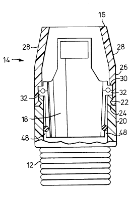
Figure 2 shows a close-up view of the releasable coupler
15 14 according to the present invention. One end of the coupler 14 is
connected to the flexible hose 12, while the other end of the coupler 14
permits the pipe 10 to slide within flexible hose 12. As will be
explained in detail below, the releasable coupler 14 can be operated in
an engaged position and in a release position. In the engaged position,
20 the coupler 14 prevents the pipe 10 from being removed or detached
from the flexible hose 12. In the release position, however, the pipe 10
can be completed removed from the flexible hose 12.
In describing the details of the releasable coupler 14
according to the present invention, reference will be made to Figure 2
and to Figures 3 and 4 in which corresponding references indicate
corresponding elements. The releasable coupler 14 comprises an outer
sleeve or cuff 16 and an inner sleeve 18. The outer sleeve 16 forms the
housing for the releasable coupler 14 and also secures the coupler 14 to
the flexible hose 12.
As shown in Figure 2, the flexible hose 12 includes a cuff
20 which has a lip 22 and a groove 24 for securing to the coupler 14.
20~6374
The outer sleeve 16 comprises respective lower and
upper sections 26 and 28. The lower section 26 forms the base of the
outer sleeve 16 and includes a groove 30 which mates and engages the
lip 22 on the cuff 20 thereby securing the coupler 14 to the flexible hose
5 12. The groove 24 also helps secure the inner sleeve 18. As shown in
Figure 3, the inner sleeve 18 has a flange 32 which runs around its
perimeter. The groove 24 is wide enough to accommodate both the lip
22 and the flange 32, with the flange 32 being seated in the groove 24
above the lip 22. The upper section 28 of the outer sleeve 16 has a
10 frusto-conical shape as will be discussed below.
The inner sleeve 18 comprises first and second half
sections 34,36 as shown in Figure 4. The half sections 34,36 are mirror
images of each other. The two half sections 34,36 form a cylindrical
sleeve when the sections 34,36 are in an engaged or closed position as
15 indicated by arrow 37 in Figure 4. The half sections each include a
button 38 for biasing the coupler 14 into an open or release position as
indicated by arrow 39 in Figure 5. The buttons 38 protrude through a
pair of apertures 40 in the cuff 16 (Figure 2). Each half section 34,36 also
includes complementary position locators, which in the preferred
20 embodiment comprise a pin 42 and a socket 44 (Figures 4 and 5). The
pin 42 in one half section 34 lines up with the socket 44 in the other
half section 36, as shown in the cut-away portion of Figures 4 and 5.
The pin 42 and socket 44 also provide a pivotal coupling
to allow the inner sleeve 18 to move between the closed position 37
25 (Figure 4) and open position 39 (Figure 5). The pivotal coupling occurs
between the first and second half sections 34,36, as follows. The pivotal
coupling comprises the pin 42 and socket 44 arrangement and
corresponding rocker cutouts 46 (Figure 4) just above the flange 32 on
each of the half sections 34,36. As will be appreciated by one skilled in
30 the art, the pin 42 and socket 44 arrangement provides a pivot or hinge
point allowing the half sections 34,36 to open when the buttons 38 are
depressed as shown in Figure 5. The rocker cutouts 46 determine how
2086374
far the half sections 34,36 can open in conjunction with the inside
diameter of the cuff 16. In addition, as shown in Figure 2, the inner
sleeve 18 includes a taper to give some clearance 48 between the
bottom portions of the half sections 34,36 and the inside of the cuff 16,
5 thereby accommodating the pivotal movement between the half
sections 34,36.
In the release position 39 (Figure 5), the half sections 34,36
spread away from the pipe 10 thereby allowing the pipe 10 to move
freely relative to the flexible hose 12 and the coupler 14. The rigid pipe
14 typically has a flange 50 (Figure 4) which is used to secure the
pipe/hose assembly 10,12 to the cleaning head 2 when the vacuum 1 is
being used in the upright mode. As can be seen in Figure 4, the flange
50 will abut against the bottom edge of the inner sleeve 18 and the
coupler 14 prevents the removal of the pipe 10 from inside the hose
12. Conversely, in the open or release position 39, the bottom edge of
the inner sleeve 18 opens to a diameter slightly greater than the flange
50 on the pipe 10. Depressing the buttons 38 causes the half sections
34,36 to spread thereby allowing the pipe 10 to be removed from the
flexible hose 12.
Referring to Figure 4, a rubber "O-ring" 52 biases the
inner sleeve 18 into the closed position 37. The O-ring 52 sits in a
groove 54 located above the bottom edge of the sleeve 18 (Figure 5).
The buttons 38, in cooperation with the pin 42 and socket 44
arrangement, provide a cantilever which expands the O-ring 52 when
the buttons 38 are depressed, thereby allowing the half sections 34,36 to
spread to the open or release position 39. When the buttons 38 are
released the tension in the O-ring 52 causes the half sections 34,36 to
snap back to the closed position 37.
The tension in the O-ring 52 can opposed by a force
30 generated by the outer sleeve 16, and more specifically the second
section 28. As mentioned above, the second section 28 has a frusto-
conical shape (Figures 2 and 3). This frusto-conical shape of the upper
2086374
-8-
section 28 of the outer sleeve 16 tends to constrict the half sections
34,36. By making the outer sleeve 16 from a rubber or elastic material,
the sleeve 16 forces the half sections 34,36 into the open or release
position 39 (Figure 5), but is counteracted by the force of the O-ring 52
5 and the inside diameter of the lower section 26 of the outer sleeve 16.
In known manner, the half sections 34,36 comprising the
inner sleeve 18 can be made using injection molding techniques. The
outer sleeve or cuff 16, in the preferred embodiment, is made from a
rubber material. The "O-ring" 52 can be made from a durable elastic
10 material.
In another embodiment of the present invention, the
diameter of the inner sleeve 18 can be dimensioned so that in the
closed position there is a tighter fit between the sleeve 18 and the pipe
10. The purpose of the tighter fit is to allow the pipe 10 to be partially
15 extended from the hose 12 and supported by the inner sleeve 18. It will
be appreciated that the inside diameter of the inner sleeve 18 must still
be such that the pipe 10 can be completely removed when the sleeve
18 is in the release position 39, i.e. the flange 50 will have to be sized to
clear the inner sleeve 18 in the open or release position 39.
It will be evident to those skilled in the art that other
embodiments of the invention fall within its spirit and scope as
defined by the following claims.