Note: Descriptions are shown in the official language in which they were submitted.
208~
,. ~ ,
MINIATURE VACUUM CLEANING SYSTEM
Many industries and endeavors such as photography, electronics and similar
items have problems with dust and other debris which must be removed from the
area to prevent contamination.
In the photography industry, photographers often purchase compressed air which
is used to blow the dust and other particles away from the instruments to prevent
them from intering with the photographic process and providing contamination of the
final product. However of course the simple propelling of the dust or other particles
away from the area acts to render these particles airborne so they again fall back
onto surfaces, in many cases coming back to the area to contaminate the ne~t
process.
Vacuum cleaners are of course readily available for cleaning various areas and
in recent years portable vacuum cleaners have become popular of a type which are of
relatively low power but which are normally suspended on a support for recharge of ~ -
a battery within the vacuum cleaner body itself. These vacuum cleaners are therefore
very portable as they do not require a mains connection cable but the suction nozzle
is relatively large and very crude and hence is unsuitable to act as a probe in
relatively small areas. -
.
It is one object of the present invention, therefore, to provide a miniature
vacuum cleaning system which allows suction to be communicated by a relatively
~mall probe into an area for cleaning of that area.
It is a further object of the present invention to provide a plurality of
~ f~ . ",~ .,,.................... ";.. ,~"."",,,, .. ,.:
,"",~ "
2 ~
r ~
different probe arrangements which are useful for different operations in cleaning
an area of this type.
It is a yet further object of the present invention to provide a system of
attachment of the various elements to an existing portable vacuum cleaner.
According to the invention, therefore, there is provided a miniature vacuum
cleaning apparatus comprising a flexible hose having a diameter less than one
inch, a connector head arranged for substantially sealing attachment to one end of
the hose, a plurality of probe elements each arranBed for separate attachment to the
connector head and an adapter head for attachment to a suction source de4ined by a
separate vacuum cleaner, the adapter head having a first connector piece arranged
for substantially sealed attachment to the hose and a second connector piece of ~-
different transverse dimensions from the first connector piece arranged for -
attachment to a suction outlet of the separate vacuum cleaner.
One embodiment of the invention will now be described in conjunction with the
accompanying drawings in which:
Figure 1 is a schematic illustration showing the various different elements
of the system.
Figure 2 is a vertical croRs section view through and end of the hose, the
connector head and one probe from the system of Figure 1.
~igure 3 is a similar vertical cross 3ectional view through the connector head
and a second probe of Figure 1.
~ '' '' ,"",,, '~ ' , X,, " ~ "~ '
~,,, ;,, , , ,: , . . . .
i ~ 2 ~
.
Figure 4 is a Yertical cross sectional view through the outer end of one of
the probes of Figure 1.
Figure 5 is an isometric view of the end of the probe of Figure 4.
Figure 6 is a vertical cross sectional view through a further one of the
probes of Figure 1.
Figure 7 is a vertical cross sectional view through a nozzle of a portable
vacuum cleaner showing the connection of one of the connector elements of -
Figure 1 to the no~zle of the portable vacuum cleaner. ~
~ :. .''
Figure 8 is a front elevational view of the connector of Figure 7. ~- .
'
Figure 9 is a front elevational view of a portable vacuum cleaner mounted in a ~-
support bracket therefor with the barrel and nozzle section removed and --
replaced by the connector from the ~ystem of Figure 1. -~
'
Figure 10 i8 a cross sectional view along the lines 10-10 of Figure 9.
In the drawings like characters of reference indicate corresponding parts in ---~
the different figures.
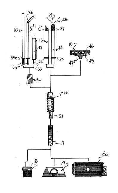
The various elements of the system are shown in Figure 1 and include a plurality -:
of elongate vacuum cleaning probes indicated respectively a 10, 11, 12, 13 and 14. --
In addition the ~ystem includes a surface vacuum head 15. hll of the probes and -~
- 3 -
~ ,",,, ~ ,' " '" ' '`:',''~'' "' '' ~" ''" "' ~ ~ '' ; ' `
,.~ ' ' ~ ' i ,,~, ", , ", ........ .. .
~',' .' ''''' ' '''j ~",":,,j , ' ' , ,":' ' ~,~ , '"
~,, ~, , , ," ,. . . .
2 ~
the head 15 are arranged for attachment to a connector head 16 which in turn canbe connected to a fle~ible hose 17 for drawing air into the probes through the hose
to a vacuum source.
For connection to the outer end of the hose are provided adapter heads 18, 19
and 20 each of which is arranged for connection to a vacuum source as described
hereinafter.
The system therefore described above can be supplied as a kit of parts which
allows the user to select from the various probes and from the various adapter heads
for attachment to an existing vacuum source to allow that vacuum source to be -~-
communicated delicately by the selected probe to a relatively small location forhigh efficiency cleaning.
Turning now to Figure 2, the probe 13 is shown attached to the connector head - -
16 which is in turn attached to ehe hose 17. Thus the connector head 16 includesa cylindrical portion 21 which receives an end of the hose attached thereto as afriction fit. A main body of the connector head 16 includes a plurality of ridges
or knurls 22 to allow ready manual grasping of the head in the manner of a pencil
so that the probe 13 can be carefully pointed by manual control to move the outer
end 23 of the probe into the required position. The connector head 16 has a bore 24
extending therethrough with a counterbore portion 25 of slightly increased diameter
to receive the outer surface of the probe 13 as a sliding fit therein. The inside
surface of the probe 13 therefore follow~ substantially smoothly through the bore
24 and into the interior of the hose 17. The diameter of the hose 17 is less than
one inch and preferably of the order of 0.5 inch which provides a relatively small
- b, -
2a,~5~
communication which can be handled simply by the manual gra~ping of the head 16
since the hose is relatively light in weight and has little resistance to movement.
The probe 13 is formed of a rigid plastics tube which thus has a diameter of the
of 0.5 inch. A separate 0 ring 26 applies a friction fit on the outside surface of
the probe 13 and it is normally maintained at a position adjacent the inner end of
the probe so that it engages the end face of the head 16 when the probe slides into
place within the counterbore 25. ---
The probe 13 a~ the end 23 has an end face cut at an angle of 45 to the ~
longitudinal axis of the cylindrical tube forming the probe. The end face is thus --
formed simply as an end of the tube having a thickness equal to the thickness of the - -
tube. The tube is formed from a rigid material so that it remains straight and
elongate when used as a probe. ---
In figures 4 and 5 are shown the end of the probe 14 which is the same as the
probe 13 in all respects e~cept at the end 27 thereof. In this arrangement the end --~
27 is cut in two planes 28 and 29 each at 45 to the longitudinal axis. Each cut ~-
end thus diverges outwardly from an end diameter 30 outwardly toward the head 16.
This arrangement allows one side of the V shaped opening thus defined to rest on a
horizontal surface thus substantially closing off that half of the opening while
the remaining half of the opening as shown in Figure 5 extends upwardly in an arch
to allow air to flow into that part of the opening and into the tube.
Both of the ends 23 and 27 include a resilient coating on the tube. The coating
material i~ indicated at 31 and is ~hown in best detail in Figure 4 where the
coating material 31 engages and urrounds the outside surface of the tube 14 and
-- 5 --
~ ~,, " , , ~""~ ,", ,,,, ",,", , ,~
2 ~
also provides a layer 32 on the inside surface of the tube 14~ The layer al~o
includes an end face portion 33 which lies on the end face of the tube. Thus all
parts of the tube which will engage the surface to be probed are covered with the
resilient or rubber layer to provide protection to that layer and prevent scratching
of delicate material such a photographic coating.
Turning now to Figure 3, the probe 10 is shown attached to the head 16. The
probe 10 comprises a flexible tube 34 of a plastics material and of a diameter
approximately one half of that of the tube 13. In the practical example, therefore,
the diameter of the flexible tube 34 is of the order of one quarter inch and this -~
approximates to the diameter of a drinking straw. The stiff and self supporting
plastics material or drinking straw which also will flex if necessary can be used
as the tube 34. The tube 34 is applied over the surface of a rigid rigid tube
portion 35 as a friction fit. The ri8id tube portion 35 projects outwardly from the
end of the tube 34 and can be inserted into a bore 35A of a coupling head portion 36
engageable as a friction fit o~er the tapered front surface of the head 16. The
portion 36 thus acts as an adapter in that it defines the bore 35 which is of
reduced diameter relative to the bore 25. An 0-ring 35B is provided on the tube
portion 35 for sealing purposes. In the example shown this is provided bY an inside
surface of the portion 36 engaging over the outside surface of the head 16.
HoweYer in an alternative arrangement the connecting portion receiving the probes
10, 11 and 12 can act as an insert to the bore 25. The rigid tube portion 35 is
identical to the imilar tube portions 35 used in the probes 11 and 12. The difference
between the probes 10 and 11 is that the probe 11 includes an accordion section 38
con~entional in a drinking straw which allows the probe to bend to a required angle
as illustrated.
~ " ;~ "" " ~ ,""" ~ ., . " .
,~", ,:, . ~: ", . ~ ~,:,., ,~.",''~ ' : . ':''
-~- 2 0 ~
The probe 12 i9 mounted on the rigid tube portion 35 as previouslg described
and attached into the head portion 36. The probe 12 however includes a rectangular
molded plastics body mounted on the rigid tube portion 35. The rectangular body
is again elongate and includes a rectangular end face 40 as best shown in Figure 6.
The end face 40 has an opening 41 communicating with the bore 42 along the in~ide of
the probe 12 which again communicates with the rigid tube portion 35. The end face
is arranged at an angle of 45 so that when the head 16 is grasped in the mannerof a writing implement the end surface 40 is positioned at an angle to lie
horizontal surface to wipe across that surface. Around the opening 41 is attached a
fabric layer 43 which covers the end face 40 except at the opening 41. The fabric 43
is of the loop type used in a hook and loop fastener fabric construction so that the
fabric 43 includes a plurality of looped fibers 44 projecting outwardly from thefabric 43. The fabric is adhesively attached to the end face. The loop fibers 44 ---
thus provide a mat or layer on the end of the probe which can be wiped across a
surface in a cleaning action. This is of course similar to the conventional
operation of a vacuum cleaner e~cept that the loop fabric including the looped fibers
is particularly advantageous in that it dows not in any way shed materials, in -
that effectively carries the dust particles so that they can be drawn into the --
opening 41 and removed. It has been found that conventional materials tend to sweep
the dust simply from one place to another whereas surprisingly the loop fibers of
thi~ type allow the dust to be drawn away and extracted rather than moved about on
the surface.
The surface head 15 of the system as shown in Figure 1 includes a flat sweeping
surface 45 including a plurality of openings 46 into which air can be drawn from the
suction connection to the head 16. The sweeping head 15 includes a c~lindrical
~ /~ 2~ ~"~
2~6~
projection 47 which engages into the bore 2S or the head 16. On the surface 45 is ~-
applied a layer of the fabric 43 including the looped fibers 44. This layer covers
the whole of the flat surface 45 except a the openings 46. This head therefore can
be used in the manner of a conventional sweeping head of a vacuum in that the
head is swept across a smooth surface. Again the looped fibers of the loop fabric
effect a surprising action upon the dust particles in that these are removed rather
than simply moved from place to place.
Turning now to the adapter heads which allow the system to be connected to a
vacuum source, a first of the adapter heads is indicated at 18 and is shown in
Figures l and 7. This adapter head comprises a flexible rubber cup having a cylindrical
wall portion 50 and an end eall 51. The end wall 51 has an opening into which is
inserted a connector sleeve 52 which engages into the end of the hose 17. This
allows the hose to be sealingly connected to the cup 50 with the sleeve 52 having
a head 53 engaging on the inside surface of the base 51. The peripheral wall 50
the cup 18 can be engaged over an open end of a conventional vacuum hose and
hense has a diameter of the order of 1.25 inches to receive the end of the conventional
hose as a friction fit therein.
The cup 18 thus can act as a first type of connector to a hose of a conventional
vacuum cleaner. The adapter heads l9 and 20 are arraD8ed for use with a portable
type of vacuum cleaner of the rechargeable type. In Figures 7 and 8 the adapter
head 19 is shown in more detail. In Figure 7 the adapter head l9 is arranged in
engagement with a nozzle 55 of a portable vacuum cleaner of the type shown under
the trademark "Power Pro'l. This type of rechargeable vacuum includes a lowermost
nozzle 56 into which du~t and debris is normally drawn into the barrel of the
vacuum. The adapter head l9 includes an insert portion 57 which is generally
~ ~",~ , ",,~ , ~,,",,,,,,, ,~ ", ~ ,, ,,,", ~ ~, ; ,,:
2 ~
~ ................................................................. - ,
rectangular in end elevation including a pair of generally parallel sides 58 -
and 59 and end faces 60 and 61. This projection is thus shaped to insert into
the slot shaped opening 56 of the nozzle of the vacuum. The side wall 60 and 61
each include a V shaped recess 62 at the outer end thereof connecting to the sides
58 and 59. This allows some flexibility of the outermost edges of the sides 58
and 59 so as to be squeezed between the end walls of the opening 56 of the nozzle.
Behind the projecting portion 57 is provided an end plate 63 which generally ~-
transverse to the longitudinal axis of the projecting portion 57, However the
plate 63 is arranged at a slight angle to this longitudinal axis so as to engage
over and close the inclined end face of the nozzle. Attached to the rear face of
the plate 63 is provided a cylindrical sleeve 64 which projects outwardly therefrom
and can receive the cup 18 thereover as a friction fit. -
As shown in Figure 7, therefore, the head 18 and the head 19 are used in ~-~
conjunction to attach to the nozzle of the Power Pro (trademark) type vacuum device.
In this arrangement as the nozzle is exposed when the vacuum is supported in the - -
mounting and recharging bracket, the adapter heads can be attached in place while
the vacuum is in the mounting bracket. Thus a vacuum device of this type can be
mounted on the wall adjacent the work station and the hose extend from the vacuum
cleaner to the work station for use of the various probes as previously described.
Turning now to Figures 9 and 10 there is shown in Figure 9 a rechargeable
type vacuum cleaner of the type sold under the trademark "Dustbuster". This
rechargeable vacuum cleaner is not shown in detail as it is well known to one
skilled in the art. The vacuuM cleaner includes a mounting and recharging bracket 70
_ 9 _
~ a ,3 ~
to which is attached a vacuum body 71 including a handle 72 and a battery and
motor section 73. A switch 74 can ve actuated to drive the suction motor to draw
air through an end face 75 and to expel that air through side vents 76. The
vacuum normally includes a vacuum barrel which is mounted on an end portion 77
projecting outwardly beyond the motor portion 73. In the "Dustbuster" (trademark)
arrangement, the end nozzle when supported in the mounting 70 i9 received within
a cup 78 and thus is not accessible for a coupling of the type shown in Figure 7.
In this arrangement, therefore, the barrel and nozzle are removed and the hesd 20
is used for direct attachment to the barrel mounting section 77. The clip is
shown in Figures 9 and 10 and comprises a flat base plate 78 having a hole 79
through which is attached a sleeve 80 for receiving the hose as a friction fit
thereon. The base plate 78 includes a pair of opposed clip legs 81 and 82 which
extend upwardly from the plane of the plate 78 at each end of the plate for e~tending
along the sides of the portion 77 of the vacuum and acting as a spring clip
arrangement for engaging the sides and holding the plate in engagement with the
front face 75 by the friction effect of the spring clip legs. As shown in Figure 10
the width of the spring clip legs is reduced relative to the width of the plate.
On the front face of the base plate 78 is applied a resilient layer 83 of a
foam rubber or the like to engage the plate 75 and to act as a seal therewith.
Around the hole 79 on the front face of the resilient layer 83 is provided a patch
of a hook fabric 84 of the type used in a hook and loop coupling. The hook fabric
includes a plurality of hooks 85 of a flexible plastics material which can engage
with the fiber~ of a flbrous filter pad 86 attached to the hooks. The filter pad
engageR over a hole in the front face 75 through which the air is drawn by the
motor in the conventional manner. The clip arrangement therefore acts to directly
attach the miniature vacuum system to the permanently mounted vacuum head and
- 10 ~
20~A ~5
provides a filter for extraction of dust and the like. It is not of course intended
to collect large quantities of debris.
Since ~arious modifications can be made in the invention as herein abo~e
described, and many apparently widely different embodiments of same made within the
spirit and scope of the claims without departing from such spirit and scope, it is
intended that all matter contained in the accompanying specification shall be
interpreted as illustrati~e only and not in a limiting sense.
' "'~
' ': -