Note: Descriptions are shown in the official language in which they were submitted.
WO 92/20427 ~ PCI /U~92/03~76
~Y8~E~8 ~ ~1~T~OD8 FOR RE~OVING ~D~:8I~l~D
Ni~TT:13R F~RO~ :BI.OOD C~ S
_iel~ o~ the I~lve~tion:
T~e invention ~enerally relates to blood
collec~iorl and processing systems and method~. In
a more particular ~ense, the inverltion relates to
systems and makhods ~or removing white blood c:ells
~xom red blood cell~ prior to transfusion or long
te~n storage.
~S~
l~ost of the whol blood collec:ted from
donors today is not itself storad and used for
transfu~ion. Instead, the whole blood is ~parated
into its clinically proven components ttypically red
blsod cells , platelets , and plasma), which are
them~;elves individually stored and used to treat a
~ultipl~ciky OI specific conditions and diseased
states . For example I the red blood cell compone~t
is used to treat anemia; the concentrated plakelet
2 0 component is used to cs:~ntrol thrombt)cytopenic
bleeding; an~l the platelet~poo~ plasma component is
used as a volume expander or as a ~ource of Clotting
Factor VIII ~or the treatment of hemophiliaO
';ystems eomposed of multiple,
interconne~cted plastic bags have T~et widespread use
~,
.
$l~$T~T~ ~
~ . . . ~ . , . . ~
... . ~ . . .. . .
. . . . . . . . .
., ........ . ~ ..... . . . .
.
. . .
.~: . . - : .
W0~2/204~7 P~/U~92/03476
and acceptance in the collectlon, processing and
storage of these blood components. In the Ur.ited
States, the~e multiple blood bag system6 are subject
to regulation by the governmentO For example, the
pl~stic materials from which the bags and tubing are
made must be approved by the governmen~. In
addition, the maximum storage periods for the blood
components collected in these systems are prescribed
by regulation.
In the United States, whole blood
components collected in a nonsterile, or "open",
~ystem (i.e. one that is open to communioation with
the atmosphere) must, under governmental
regula~ions, b transfused within twenty-~our hours.
However, when wholP blood components are collected
in a sterile, or "closedl', system (i.e., one that is
closed to communication with the atmo~phere), the
red blood cells ca~ b~ stored up to forty-two days
(depending upon the type of anticoagulant and
storage medium u ed); the platelet concentrate can
be stored up to f ive days (depending upon the type
of storage container); and the platelet-poor plasma
may be ~rozen and stored for even longer p~riods.
Conventional systems of multiple, interconnected
plastic bags have met with widespr~ad acceptance,
because these systems can reliably provide the
desired sterile, "closed" envirsnment ~or ~lood
collection and processing, thereby assuring the
maximum available storage periods.
: 30 In collecting whole blood components Por
trans~usion, it is desirable to minimize th~
; presence o~ impurities or other material~ that may
cause undesired side effects in the recipient. For
. example, because o~ possible febrile reactions, it
is genera:Lly consider~d desirabl to trans~`use red
SIJ~TIIU~ SI~ET
,
: - .
W09~/204~7 PCT/lJS92/03476
- 3 ~ ;~0~'-'jl l
blood cells su~stantially ~ree of the white hlood
cell components, particularly for rPcipients who
undergo frequent transfusions.
One way to remove white blood cells is by
washing the red blood cells with saline. This
technique is time con~uming and inefficierlt, as it
can reduce the number of red blood cells available
~or transfusion. The washing process al~o expos~s
the red blood cells to co~munication with the
atmosphere, and thereby constitutes a "non~sterile"
entry into the storage sys~em. Once a non-sterile
entry is made in a previously closed system, the
system i5 consldered "opened", and transfusion must
occur within twenty-four hours, regardless of the
lS manner in which the blood was collected and
proces~ed in the first plaoe. In the United States,
an entry into a blood collection system that
presents the probability of non-sterility that
exceeds one in a million is generally considered to
con~titute a "non-sterile" entryO
Another way to r~move white blood cells is
by ~iltration. Systems and methods for
accomplishing this within the context of
conventional multiple blood bag configurations are
described in Wisdom U.S. Patents 4,596,657 and
4,767,541, as well as in Carmen et al U.S7 Patent~
4,810,378 and 4,855,063. In these arrangements, an
inline white blood call filtration device is used.
The filtration can thereby he accomplished in a
closed system. How~ver, the filtration processes
associated with the~e arrangements r~uire the extra
step of wetting the filtration device before use
with a red blood ~ell additive solution or the like.
. This adde~ ~tep complicates the filtration process
and incr~as~s the processing time.
, :
$~T~T~
.
.
. . . .
.
. ,
..
W092/20427 PCT/~Ss2/03~7~?
Other syste~s and methods for removing
white blood cells in the context of closed, multiple
blood ba~ confisurations are described in Stewart
U.S. Patent 4,997,577. In these filtration systems
and methods, a transfer assembly dedicated solely to
the removal of white blood cells is used. The
transfer assembly is attached to a primary blood
collection container. The transfer assembly has a
transfer container and a first fluid path leading to
the transfer container that includes an inline
device for separating white blood cells from red
blood cells. The transfer asse~bly also has a
second fluid path tha~ bypasses the separation
device. U~ing these systems and methods, white
blood cells are removed as the red blood cells are
conveyed to the transfer container through the fir~t
fluid path. The red blood cells, now substantially
free of white blood cells, are then conveyed ~rom
the transfer container back to the primary
collection container for storage through the second
fluid path, this time bypassing the ~eparation
device.
A need still exists fGr further improved
systems and methods for removing undesired matter
from blood components prior to trans~usion or
storage in a way that lends itself to use in closed
multipl~ blood bag system environments.
~u~a_Y of th~ ~e~tio~:
The invention provides a ml~ltiple container
blood collection system ~or conveniently processing
all the various components of blood. The system
includes a device for ~eparating undesired matter
~rom some of the components prior to storage. The
system is ~rranged so that only single pass
through t:he separation device is required during a
SlLqBSTlT~ S~EÇI~
.
.
W~92/20427 ~'~/US92/~3476
_ 5
given proc~ssing sequence.
In one embodiment, the sy~tem comprises a
blood collection assembly ancl an associated transPer
assembly having first and second transfer
5containers.
~o transfer paths lead to the first
transfer container. The ~irst trans~er path
includes means for separating undesired matter from
blood. A second transfer path bypasses the
10sep~ra~ion means.
third transfer path leads to the second
transfer container. The third path communicates
with the second transfer path, also bypassing the
separation means that is present in the first
15transfer path.
The system also includes means for
establishi~g communication between the blood
collection assembly and the first, second and third
transfer paths.
20In this arrangement, the sy~tem includes
flow control means that is operable in thr~e modes:
(i) In its first mode, the flow
control means directs a first quantity of blood ~rom
. the blood collection assembly for collection in the
; 25second txansfer container through the second and
third transfer paths, therefore bypassing the
separation means. In this way, a ~irst quantity o~
blood can be freçly and easily transferred within
the ~ystem without being passed through the
30separation means.
(ii~ In its s~cond mode, the flow
control means direct~ a second quantity of blood
fr~m the blood collection assembly to the first
transfer container through the first transfer path.
35In this way, the second quantity of blood can be
~IT~
.
.
:. :
.
.
. . . .
wog2/2o427 ~'C~IU~9~/03476
6 --
s 1 Q~
passed through the separakion means for removal of
the undesirable matter.
(iii) In its khlrd mode, the flo~l
control means directs the second quantlty of blood
~now substantially free of undesired matter) from
the first transfer contain,er back to the blood
collection a~sembly for storage. This transfer
occurs thxough the second flow path, thereby
bypassing the separation means. In this way, blood
previously freed of undesired matter can be easily
transferred back to the blood collection system for
storage without being unnecessarily subjected to a
second pass through the separation means.
In a preferred arrangement, the blood
collection assembly includes a satellite bag which
contains an additive solu~ion for the blood that is
to be stored free of undesired mattex. In this
arrangement, the ~low control means is operative in
a fourth mode for directing the additive solution
from the satellite bag to the primary container
through a path that bypasses the separation m~ans.
The additive solution is added to a blood component
prior to its being pas~ed through the separation
device. As in the other arrangements, the system
faciiitates multiple blood component processing with
only a single pass through the inline separation
means.
In a pre~erred embodiment, the blood
collection assembly and the transfer assembly
comprise separate closed subassemblies. In this
arrangemenk, the means for establishing
communication includes means for attachiny khe ~lood
collection subassembly to the transfer subassembly
without ot:herwise opening the closed subassemblies
t~ communi.cation with the atmosphere.
... . . .
:' , : .
~ ~ .
: :
,
W~92/204~7 P~/U~92/~3~76
~ 7
2~
The invention alsc) provides methods o~
collecting blood components substantially free of
undesired matter usin~ the systems as just generally
describ~d.
Other feature~ and advantages of the
invention will become apparent upon review of the
following description, drawings, and appended
claims~
Brief Des~riptio~ of t~e Dr~win~:
Fig. 1 is a schematic view of a blood
collection system that includes a blood processing
assembly and a transfer assembly that embody the
f2atures of t~e invention;
Fig. 2 is a schematic view of the system
lS shown in Fig. 1, with the blood transfer assembly
attached to the blood processing assembly showing
transfer of plasma and platelet componsnts to a
transfer container;
Fig. 3 is a schematic view of the system
shown in Fig. 1, ~howing ~iltration o~ the red blood
cells to remove unde~ired matter, with the platelet
and plasma being independently processed in a
separate subassembly;
Fig. 4 is a schematic view o~ the system
shown in Fig. 1, showing the return of the ~iltered
blood cells to the collection assembly for storlge;
; ~ig. 5 is a sche~atic vi~.w of the 8y5t .m
shown in Fig. 1 with tha container holding the
filtered blood separated from the system ~or
storage;
Fig. 6 is a schematic view o~ another blood
collection system that :includQs a blood processing
ass~mbly a.nd a transfer assembly that embody the
features oi` the invention; and
Fig. 7 is an enlarged side sectional view
SlJ~STiTlJT~ S~ET
.: . ~ . . . : .
-
:. :
. ~ . :
, . . .
W092/~427 Pcr/us~2/
~ 3~ 8 -
of the sterile connection devices associated with
the systems shown in Figs. 1 iand 6.
D~s~riptio~ o tho Pr~ferre~ Embo~i~ent~:
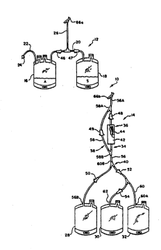
A blood collection system 10 that embodi~s
the features of the invention is shown in Fig. 1.
The system 10 comprises a blood collection assemhly
12 and a tra~sfer assembly 14.
In use, the assambly 12 serves to initially
collect a unit o~ blood from a donor and to allow
conventional centri~u~al separation of the blood
into at least two component parts. The assembly 12
serYes to process the blood into first and second
component parts. In use, the assembly 14 also
serves to allow the separation of unde~ired matter
from the second component prior to the storage.
In the embodiment shown in Fig. 1, the
transfer assembly 14 ~omprises an initially separate
subassembly that is not joined to the blood
processing assembly 12. In this arrangement, the
assembly 12 also becomes an initially separate
subassembly.
According to the invention, prior to usP,
the separate transfer subassembly 14 need not
contain any fluids, stora~e mediums, and the like
(except ~or any entrapped air). Preferably, all
: such fluids are contained in the blood collection
subassembly 12 prior to use. The invention thus
provides the capability o~ having a blood collection
system lO compvsed of a fluid containing (or ~Iwet~)
subassembly 12 and a Pluid ~ree (or "dry")
subassembly 14. This arrangement serves to avoid
the application of the regulatory requirements
governing fluid-containing systems upon the transfer
assemhly 14O It should be appreciated, however,
that the transfer assembly 14 can be made as an
~ TITI~ ~ FT
.
.: , , .
~ ............ ..
W092/20427 PCr/US~2/03476
g
~3~
integral part of the assembly 12 and/or, if desired,
con~ain fluids.
In the embodiment shown in Fig. 1, the
bl~od collection and storage subassembl~ 12
5 comprises a blood bag system having a primary bag or
container 16 and a satellite bag or container 18
attached to the primary ]bag 16 ~y integrally
attached tubing 200
In use, the primary bag 16 ~which is also
10 called a donor bag) receives whole blood ~rom a
donor through integrally attached donor tubing 22
that carrie5 an phlebotomy needle 24. A suitable
anticoagulant A is contained in the primary bag 16.
The whole blood is æeparated by
15 conventional centrifugation techniques within the
primary bag 16 into a red blood cell component and
a platelet-rich plasma component. During such
separation techniques, a layer of white blood cells
(commonly called the "buffy coat"~ forms between the
20 red blood cells and the platelet-rich plasma.
The tu~ing 20 that integrally connectq the
bags 16 and 18 is also joined to an outlet branch
tubing 26 for connection to the transfer subassembly
14~
The trans~er assembly 14 includes several
trans~er bags or containers 28, 30, and 32. The
transfer bag 28 is intended to receiv2 red blood
cells in the course of removing white blood calls
from the recl blood cells prior to storage. The
30 trans~er containers 30 and 32 are intended to
: accommodate the separation of the platelets ~rom ths
platelet-r:ich plasma and ko ultimately store the
resulting plat~let-poor plasma and concentrat~d
pl~telet compone~ts.
In the illustrated embodiment, the transfer
St~ll~ ~IE~T
- ` .
W092/20427 PCT/US92/0347h
bag 32 ultimately serves as the storage container
for the platelet concentrate, and the transfer bag
30 ultimately serves as the storage container for
the platelet-poor plasma.
The transfer a~sembly 14 includes a first
transfer path 34 that leads to the trans~er
container 28. The path 34 includes a device 36 for
separating undesired matter cells from blood~
It should be appr~ciated that the transfer
lo assembly 14 can be used to remove all types of
undesired materials from dif~erent types blood
cells, depending upon its particular construction.
In the illustrated embodiment, the assembly 14 is
intended to remove whit~ blood cells (and preferably
also platelets) from the red blood cells prior to
ætorage. In this arrangement, the separation device
36 includes a housing 42 containing a conventional
filtration medium 44 suitad for the ramoval of white
blood cells and platelets fr~m red blood cells. The
filtration medium 44 can include cotton wool,
cellulose acetate or another synthetic fiber like
polyest~r.
It should also be appr~ciated that
separation can occur by various centrifugal and non-
centrifugal techniques, and not merely ~'~iltration"
in the technical sense. Separation can occur by
.absorption, columns, chemical, electrical, and
electromagnetic means. The term "separation device"
is broadly used in this specification encompa~s all
of these separation techniques as well.
The transfer assembly 14 ~urther includes
a second trans~er path 38 that also leads to the
transfer contEIiner 28. However, unlike the transfer
path 34, this ~ran~r path 38 bypasses the
35 separation d8YiC2 3 6 .
i
.
W0~2/20~27 PCT/US')2/03~76
2a.~s~
The transfer assembly 14 also includes a
third transfer path 40 that communicates with the
second transfer path 38. The third path 40 leads to
the transfer container 32, byp~s~ing the separation
device 36.
Because o~ this construction, it is
possible to selectively direct fluid within the
system 10 into and out of the containers 2~, 30, and
32 in paths that either pass khrough the separatlon
device 36 (i.e., via the fluid path 34~ or bypass
the separation device 36 (i.e., via the fluid path
38).
The assembly 14 can be variously
constructed. In the illustrated embodiment, fluid
path 34 takes the form of a length o~ flexible
tubing 56. The ~ubing 56 includes first and second
opposite end portions 56A and 56B. The tubing end
56B is connected to th~ transfer container 28. The
separation device 36 i~ located inline bQtween the
opposite end portions 56A and 56B.
In this arrangemen~, the ~luid path 38 also
include a length o~ flexible tubing 58. One end
58A joins the first ~luid path tubing 56 between
tubing end 56A and the separation device 36. The
other end 58B joins the ~irst fluid path tubing 56
between the separation device 36 and the tubing end
56B.
In this arrangement, the ~luid path 40 also
includes a l~ngth of flexible tubing 60. One end
60A is connected to the trans~8r container 32. The
other end 60B joins the tubing 56 between its
junction with tubing end 58B and its tubiny end 56B.
A len~th o~ ~lexible tubing 62 attached to the
trans~er container 30 joins the tubing 60 between
! 3 5 tubing end~ 6OA and 6OB.
.
~TITUTE $~ET
.
. ` . .. . . .
,
,. . . .
, . ~ . . , .. -. , ~ . .
.
- . ~. ~ .
I .. . .
~ ... . . .. ... .
W092/20~27 PCr/US92/03475
- 12 -
'2 ~ 8 j 1 i~
The transfer a~sembly 14 includes flow
control means for directing fluid flow between the
collection subassembly 12 ancl the various paths 34,
28, and 40 of the transfer subassembly 14. In the
illustrated embodiment, the flow control means
comprise a series of conventional roller clamps 46
to 54 arranged as shown in Fig. 1. By selectively
opening and closing the roller clamps 46 to 54, the
system 10 can he selectively placed by the user in
different processing modes.
A first processing mode directs a first
quantity of blood from the assembly 12 for
collection in the transfer container 32 via the
second and third transfer paths 38 and 40. The
first quantity of collected blood thereby bypasses
the separation device 36.
A second processing mode directs a second
quantity of blood from the assembly 12 to the
transfer container 28 via the ~irst transfer pa$h
34. The second quantity of blood thereby passes
through the s~paration devic2 36 to remove the
undesired materials. This mode is intended to be
us~d to remove und~sired matter from those
; components prior t~ storage.
A third mode directs the second quantity o~
blood from the transfer container 28 back to the
: assembly 12 via the second flow path 38 for storage,
thereby bypassing the separation device 36. This
mode avoicl~ the unnecessary return of filtered
components bac~ throuqh th~ separation device 36.
The bags and transfer paths associat~d with
the assemblies 12 and 14 can be made from
, conventional approved medical grade plastic
: ~aterials, such as polyvinyl chloride plasticized
with d:i-2-ethyl~hexylphthalate (DEHP).
SUBSTITUTE SHEE~T
, ' :
~, .
.:, `
: . . .
~O9~/204~7 Pcrluss~/
- 13 - ~,s'~
Alternatively, transfer container 32, which i5
intended to store the platelet concentrate, can be
made of polyolefin material (as disclosed in
Gajewski et al u.s. Patent 4,~.40,162~ or a polyvinyl
chloride material plasticized with tri-2-ethylhexyl
trimellitate (TEHTH). These materials, when
compared to DEHP-plasticized polyvinyl chloride
materials, have greater gas permeability ~hat is
beneficial for platelet storage.
The system 10 includes a means ~or
connecting the initially separate subassemblies 12
and 1~ together for use. The connection means is
associated with each of the initially separate
a~semblies 12 and 14. The connection means permits
selective attachment of the transfer assembly 14 to
the blood collection assembly 12 (as shown in Fig.
2).
In the embodiment shown in Fig. 1, the
connection means comprises two mating ~terile
connection devices (deslgnated 66a and 66b). The
devices 66a and 66b (see also Fig. 7) are described
in Granzow et al U.S. Patents 4,157,723 and
~,265,280, which are incorporated herein by
re~erence. One device 66a i~ carried by the outlet
branch 26 of the assembly 12. The other device 66b
is carried at the tubing end 56A of the transfer
assembly 14.
As shown in Fig. 7, the sterile connection
devices 66a and 66b each generally includes a
housing 70 having a normally closed, meltable wall
72 made o~ a radiant energy absorbing material. The
housings 70 are joined together with mating bayonet-
type couplers 74a and 74b/ with the walls 72 placed
in facing contact. When connected and exposed to
radiant energy, the walls 72 melt at temperatures
SU8S~ITUTE S~ET
,.. .. .. . , , ... ... ,., , : : . .
. .. . .. .. . . . ~ , . . .
.. . ~ . . . . . . . .
.... . . . . : .. ~ ~ .:
. . . . . .
.. . . . . ... .
. . . . . . .
. . ~. . . ~
.... ~
.
W092/2U4~7 PCr/US~2/03~7
that result in the destruction of bacteria, while at
the same time opening a f:luid path between the
connected housings 70~
The devices 66a and 66b normally close the
associated assembli~s 12 and. ~4 from communication
with the atmosphere and are opened in conjunction
with an active sterilizatioll step which serves ~o
sterilize the regions adjacent to the
interconnecting fluid path as the ~luid path is
being formPd. These devices 66a and 66b also
hermetically seal the interconnecting fluid path at
the time it is formed. The use of these sterile
connection devices 66a and 66b assures a probability
of non-sterility that exceeds one in a million. The
devices 66a and 66b thus serve to connect the two
assemblies 12 and 14 without compromising the
sterile integrity of either.
Alternately, the connection means can
comprise the sterile connecting system disclosed in
Spencer U.SO Patent 4,412,835 (not shown). In this
arrangement, this system forms a molten seal between
the tuhing end 26 and 56A. Once cooled, a sterile
weld is formed.
The assemblies 12 and 14, once sterilized,
each consti~utes a sterile, "closed" system, as
jl~dged by the applicable standards in the Vnitad
States.
In use, whole blood is collected (via the
donor tube 22) in the primary bag 16. The collected
whol~ blood is then separated within the primary bag
16, preferably by centrifuging, into red blood cells
(RBC) and platelet~rich plasma (PRP). An
intermediate white ~lo~d cell layer (BC~ also forms.
Th~ assembly 12 i5 next joined to the
assembly 14 (as Fig. 2 shows). The flow control
$~;TIT~ ~EET
,
. . .
~ . . , . :
:: , .: ~ , ...
W092/20427 PCT/US92/03~76
- 15 -
means is placed into its fi~.st processing mode by
closing clamps 47; 48; 50; ~nd 54 (if previously
opened) and by openi.ng clam]ps 46; 49; and 52 (if
previously closed).
The platelet-rich plasma ~PRP) is conveyed
from the primary bag 16 through second and third
transfer paths 38 and 40 by con~entional techniques
(for example by using a plasma expresser) into the
transfer bag 32. In this step, attempts are made to
leave all the red blood cells and as many white
blood cells as possible in the primary bag 16. The
handling of the platelet-rich components in this way
avoids use of the separation device 36.
The clamp 52 is closed, and the transfer
bags 30 and 32 are detached in a sterile fashion (as
Fig. 3 shows). The detachment can be accomplished
using a conventional heat sealing device (~or
example, the Hematron~ dielectric sealer sold by
Baxter Healthcare Corporation~, which forms a
hermetic, snap-apart seal in the tubing 60 ~this
seal is schematically shown by an "x" in Fig. 3 ~.
The donor tubing 22 is preferably sealed and
disconnected in the same fashion (as shown in Fig.
2) before joining the two assemblies 12 and 14
together.
As Fig. 3 also shows, the platelet rich
pla~ma can undergo subsequent centrifug~l separation
within the transfer bag 32 into platelet concentrate
(designated PC in Fig. 3) and platelet-poor plasma
3C (desi~nated PPP in Fig~ 3~. By opening clamp 54,
the platelet-poor plasma (PPP) is transferred in~o
the bag 30 ~or storage, leaYing the platelet
concentrat~e in the bag 32. The transfer bags 30 and
32 are then separated by the snap-apart seals "x" in
the ~ubing 32 (as shown in Fig. 3) ~or subsequent
~IU~5Tl~lJTE S'~
,. , ., ~ , . . .
: .
.
. .. . . .
.
WO9~/20427 pcr/lJs92/o34~L6
- 16 -
'~ ~J ~
storage as individual components.
The flow control mealls is next placed into
its second processing mode to transfer the red blood
cells ~with associated white blood cells) to the
transfer container 28 via the separation device 36.
In the illustrat~d embodiment, th~
satellite container 18 holdr= a suitablP storage
solution 5 for red blood cel].s. One such solution
is disclosed in Grode et al U~S. Patent 4~267,269.
In this arrangement, prior to assuming the second
processing mode, the flow control means is ~irst
placed into a processing mode for directing the
additive solution S from the satellite bag ~8 to the
primary bay in a path that bypasses the separation
device 36. This mode is ascomplished by closing
clamp 48 and opening clamps 46 and 47. The solution
A is transferred to th~ primary bag 16 via path ~0.
The second processin~ mode then proceeds by
: closing clamps 47 and 49 and opening olamp 48. As
shown in Fig. 3, the primary bag 16 is li~ted above
the transfer bag 28, and the red blood cells (with
associated white blood cells and additive solution
S) are conveyed by gravity flow ~rom the bag 16
through the fluid path 34 and separation device 36
into the transfer bag 28. The undesired matter
(i.e., white blood cells and platelets) are removed
~rom thQ red blood cells by the separ~tion device
36.
~hile th~ two assemblies 12 and 14 are
still attached together, the flow control means is
placed in i.t5 third mode, as Fig~ 4 shows. This is
accomplishe.d by closing clamp ~8 and opening clamp
49, The transfer b~g 28 is li~ted above assembly
12. The re.d blood cells and additive solution, now
substantially ~ree of the undesired white blood
. ~ .
W~92/204~7 PCT/U~')2/03~7
- 17 -
~ i ~ 3 . i
cells, are. returned by gravity flow from the
transfer bag 28 through the fluid path 38, bypassing
the separation device ~6.
The filtered red blood cells can be
returned for storage either to the pri~ary bag 16
(by opening clamp 46 and closing clamp 47~ or to the
now empty satellite bag 18 (by closing clamp 46 and
opening clamp 47). In the illustrated and preferred
embodiment, the filtered r~d blood cells are
conveyed to the satellite bag 18 for storage.
Should air be trapped in ~he transfer bag
28, it may be necessary to first transfer the air
through bypass path 38 into the bag 16 or 18 in
which the red blood cells will not be ultimately
returned for storage.
As Fig. 5 shows, the satellite bag
: containing the filtered red blood cells and additive
solution is detached ~rom the blood collection
assembly 12 for storage.
In one alternatiYe arrangement (not shown~,
the assembly 12 could be made without an associated
satellite bag 18. In this arrangement, the red
blood cells are returned to the primary bag 16 for
storage after filtration.
In another alternative arrangement tal60
not shown), the assembly 12 could include an
associat d empty satellite bag9 without an additive
solution. In this arrangement, the red blood cells
are return~d to the satellite bag aPter filtration
~or ~torage :Eree o~ an additive ~olution.
Yet another alternative arrangement is
shown in Fiy. 6. In this embodiment, like the
embodiment shown in Fig. 1, the assembly 12 inoludes
a primary bag 16 and a satellite bag 18. Also like
the embodi.ment shown in Fig. 1, the a~sembly 14
.
,. , . . -
.
,
, ' ' :
W092/20427 P~T/lJ~2/03~7..6
- 18 -
includes a transfer container 28 with two associated
flow paths 34 and 38, one 34 which includes ~he
separation device 36, one 38 which does not.
Unlike the Fig. 1 embodiment, the transfer
bags 30 and 32 are not associated with the assembly
14, but instead form an integral part of the
assembly 12.
In using the embodiment shown in Fig. 6,
whole blood i5 collected in the donor bag 16, where
it is separated into red blood cells, platelet-rich
plasma, and white blood cells in the manner already
described in the Fig. 1 embodiment. In its first
processing mode, the platelet-rich plasma is
conveyed to the transfer bag 32 for processing.
Like the Fig. 1 embodiment, th~ path between the
primary bag 16 and the transfer bags 30 and 32
bypasses the separation dPvice 36O
The transfer bag~ 30 and 32 are then
detached from th assembly 12 in the manner
previously described with respect to assembly 14.
The assembly 12 is then attached to the assembly 14,
and the processing through $he remaining modes
proceeds as previously described.
In the illustrated embodiments, the entire
filtration proce~s (including the attachme~t and
detachment of the assemblies 12 and 14) can be
accomplished in less than five minutes. All blood
components processed are subqtantially ~ree o~ the
undesired matter~ In the preferred embodiment,
where the all the fluid trans~ers are made using
~terile connection techniques, the processing and
inline filt3-ation have occurred without compromising
the.sterile integrity of any collected compon~nt or
reducing their storage life.
: 35 Various modifications of the invention will
SW~TIT~ S~~
.
. : . . : . .
. . . --_, -. . .
.
.~ .
~ 92/20427 PCI/US92/03~76
-- 19 --
be apparent to those skilled in the art within the
purview of the following claims.
' ' ~
.
SUBSlTrU~ SH~E~
'';' ' ~ i ` - : :
, . . `., .
.~ .- , . . .