Note: Descriptions are shown in the official language in which they were submitted.
2 ~
- 8TENTLESS HEART VALVE AND HOLDER
R~ck4~ou..~ of the T~vention
Field of the ~rt
The ~l ~ ~~nt invention i8 directed to ~ heart valve
holder nnd more particular~y to ~ device for holding a
~tentless tissue heart valve prosthesis during implantation
~nd to ~ combination ~tentless t~ r~ he~rt valve
prosthesis and detachable holder.
niScussion of ~he Prior ~rt
Surgically-implanted heart valve ~LG~~heses have
extenAe~ the life ex~e~ancy of many patients who had
defective natural valves. Such prosthe~es can be either
mechanical or derived from human or animal donors. The
aortic prosthesis is implanted in the patient during a
surgical procedure in which a 6egment of the aorta nearby
the natural valve is ~lit open so that the malfunctioning
leaflets can be cut out and the prosthetic valve is ~u~ed
within an intact segment of the aorta adjacent to the
heart. The eurgical ~1 G~edu~ e is exacting due to the
Furgeon'~ cramped quarters. Holding the implant in place
while the surgeon places the DuL~ es to attach it to the
interior of the patient'~ aorta presents an especially
difficult problem.
To aid the surgeon during the implant procedure, it is
known to use both dicposable and nondisposable holders to
position the valve during surgery. However, the known
valve holders are large and cumbersome. For instance U.S.
Patent 3,409,013 describes a nondisposable ~urgical
instrument having a shank with pivotal bowed jaWc mounted
~at one end for gripping a heart prosthesis having a ~u~le
~ing by the suture ring. Means is also provided for
~ & 8 ~ 5 ~ ~
_ holding taut a plurality of ~LUL__ to be ra~-e~ through
the D~LuLe ring attached to the valve. The ~ L_ ~re
meant to be used in 6ecuring the prosthetic valve into the
patient'~ aorta. A ~ore recent development is the
S dieposable valve holder disclosed in U.8. Patent 4,185,636,
which al~o utilizes a plurality of circumferentially ~paced
l-gs attached to central holder apparatu~. The ~ewing ring
of the prosthetic heart valve i~ attached by ~L~L~ to a
~olding di~c ~lideably positioned upon the central rod of
the valve holder. The~e known valve holders, howeve., are
unwieldy and obstruct the 6urgeon'~ view. Moreover, thiC
type of valve holder requires that the prosthetic valve
have a sewing ring for grasping by the holder or to which
the holder is laboriously attached by DuLules immediately
prior to the curgery.
Each of the known types of prosthetic heart valve
also has its peculiar limitations. ~or instance,
homografts from donor human heart~ are difficult to obtain
in exact ~izes, cannot be sterilized, and require extensive
tests to determine the risks of transmitting diseases and
of donor tissue incompatibility. Merh~n~cal implants,
although readily available in many types and ~izes, do not
duplicate the natural means of attaching the leaflets to
the aortic wall and are excessively rigid, thus making
installation difficult.
Bioprostheses ~LGc~ed from animals provide an
acceptable alternative to homografts and merhAnical valves
becau~e they can be provided in acceptable quantities and
in a variety of cizes, they are more flexible than
mechanical models, and they can be sterilized and tested
for ~ Ase. However animal valves are commonly trimmed by
cutting away the aortic wall between the leaflets and
leaving only the tissue to which leaflets are attached. To
2 ~
L the remaining structure, animal valves are u~ually
~upported by ~etallic or plastic ~tent~, often augmented by
a ~ewing ring usually at~ach~A to the ~xterior of the
prosthe~i6 to _id in surgical attachment ~nto the patient'~
aorta. The ~ewing ring and/or ~tent occupie~ ~pace in the
patient's annulus, thereby r~ in~ the orifice area of the
valve and ~ -~guently increa6ing ~uL~ulence and the
~~sure gradient. In addition, the ~tent tends to be
somewhat rigid, requiring the leaflet~ to ab~orb much of
the ~tress during valve closure. Becau~e the heart beats
a~oximately 40 ~illion time~ per ye r with closing
pressures up to 4 psi, ~ignificant fatigue and wear can
occur to a heart ~alve leaflet when it must absorb the
~tress caused by heartbeat.
It is common practice to tan animal valves to render
the animal ti~sue relatively inert with respect to the
living host environment and to provide a fixed
configuration. As disclosed in ~Ancock et al U.S. Patents
3,966,401 and 4,050,893 and Angell et al U.S. Patent
3,983,581, animal heart valves can be tanned using a
nning fluid under differential pressures across the valve
ranging from 20 mm Hg to 120 mm Hg. However, it i~ known
that obtaining fixation at these high internal pressures
results in considerable loss of resilience to the collagen
fibers in the heart valve. As disclosed in Lane U.S.
Patent 4,372,743, a preferred method of fixation at low
pressure elim~nate~ these difficulties. According to this
low pressure method, fixation of an animal heart valve is
accomplished without substantial lo~s in resilience to the
internal collagen fibers and without shrinkage of the valve
by ~ubjecting it to a t~nning fluid, preferably
glutaraldehyde, at a differential pressure across the valve
of from zero to 4 mm Hg. In this prore~lre, an internal
mechAnical restraint is positioned within the valve prior
4 2û865 ~ 5
to fixation so as to prevent shrinkage and distortion
of the valve during the fixation step. the internal
restraint is removed once the valve ha~ been tanned.
Despite the advantages provided by low pressure
tanning, it can be seen from the foregoing discussion
that the need exists for new and improved aortic heart
valves, especially those derived from animal donors, and
for holder~ that aid in their surgical implant.
SUMMARY OF THE INVENTION
Various aspect of the invention are as follows:
A stentless aortic valve prosthesis comprising
an animal aortic segment having an external surface
and an internal surface, the aortic segment further
comprising an aortic root, an outflow rim adjacent
the aortic root, an inflow rim, a left coronary
artery, a right coronary artery, a right coronary
septal shelf, a plurality of valve leaflets, each
va~ve leaflet having cusps and edges with the
adjacent edges of the valve leaflets meeting to form
commissures, a pse~o~nnulus line located adjacent
the commissures along the internal surface of the
aortic segment, and coronary openings formed by
cutting away the left and right coronary arteries
while leaving intact a band of aortic wall adjacent
the outflow rim.
A stentless aortic valve prosthesis comprising
an ~n;~l aortic segment having an external surface
and an internal surface, the aortic segment further
comprising an aortic root, an outflow rim adjacent
the aortic root, an inflow rim, a left coronary
artery, a right coronary artery, a right coronary
septal shelf, a plurality of valve leaflets, each
valve leaflet having cusps and edges with the
B
~ ~ .
~ o ~ ~ 5 ~ 5
4a
adjacent edges of the valve leaflets meeting to form
commissures, and a pseudoannulus line located
adjacent the commissures along the internal surface
of the aortic segment, the aortic segment further
comprlslng:
coronary openings formed by cutting away the
left and right coronary arteries while leaving intact
a band of aortic wall adjacent the outflow rim; and
a suturable covering affixed along the entire
right coronary septal shelf on the external surface
of the aortic segment, and the inflow rim on both the
internal and external surfaces of the aortic segment;
the suturable covering comprising edges and covering,
at the outflow rim, an area r~nn;ng along the
internal surface of the aortic segment between the
pseudoannulus line and the coronary openings, leaving
uncovered a portion of aortic wall between the edges
of the suturable covering and each commissure.
A combination valve holder and prosthetic aortic
segment comprising:
a stentless aortic valve prosthesis comprising
an animal aortic segment having an external surface
and an internal surface, the aortic segment further
comprising an aortic root, an outflow rim adjacent
the aortic root, an inflow rim, a left coronary
artery, a right coronary artery, a right coronary
septal shelf, a plurality of valve leaflets, each
valve leaflet having cusps and edges with the
adjacent edges of the valve leaflets meeting to form
commissures, a pseudoannulus line located adjacent
the commissures along the internal surface of the
aortic segment, and coronary openings formed by
cutting away the left and right coronary arteries
while leaving intact a band of aortic wall adjacent
the outflow rim;
a disposable holder body having an elongate
detachable handle; and
B
~ Q ~
4b
a plurality of means for detachably attaching
the holder body to the covering on the aortic
segment.
By way of added explanation, many of the above-
described problems are overcome by the stentless animal
aortic valve prosthesis disclosed herein. The invention
provides a reversible stentless animal heart valve,
preferably porcine, tanned at low pressure to retain
natural flexibility. Instead of a stent or sewing ring
the prosthesis has a minimal biocompatible suturable
covering, preferably cloth, along the inflow rim of the
valve to reinforce the suture attachment of the
artificial valve to the human heart valve annulus. Thus
a minimum of critical space in the annulus is taken up by
the prosthetic device and the amount of turbulence in the
annulus caused by the prosthesis is thereby decreased.
The aortic segment is left untrimmed except for
removal of the right and left coronary arteries so that
an intact band of aorta remains above the two coronary
openings for the purpose of maintaining commissural
alignment and preventing valvular distortion during
implantation. However, the portions of aortic segment
contiguous to the coronary openings optionally can be
trimmed away by the surgeon without impairing the shape
or function of the valve.
B
2~8~5~
_ A ~i-po--hle valve holder body i~ al~o provided, being
a tiny pla~tic member for preattachment to the valve at the
time of manufacture. The stentle6~ valve and valve holder
thu~ can be etored and ~old as a ~ingle unit.
s
To prepare the animal valve for tanning~ a ~egment of
animal aorta having attarb~A ~tubs of the left and right
coronary artery i~ eYcir~~ from an animal heart, prefer_bly
porcine, making ~ure that an intact band of aorta remain~
thereabove and that the three valve leaflet~ and the
~inl~FE- of Val~alva al~o remain intact.
Preferably only those valves are ~elected for use that
have a uniform lateral profile. To ~levent distortion
_ functions like a sewing ring in providing the physician
with a firm ~.o~.~ for suturing the prosthesis into place.
m e covering extends along the ~nflow rim, both
internally and ~xternally, and along the exterior surface
of the entire right coronary ~eptal ~helf. To provide the
~ eo~l with a guide to suture placement, the covering can
be ~ewn along the ~nflow ~nn~lus with ~uture of a
~G--L~a~ting color. ~ar~n~ of any type clearly vi~ible to
the surgeon during implant and located on the surface of
the covering along the inflow rim above the center of each
of the three valve cusps aid the ~urgeon in aligning the
valve within the patient'~ natural aorta. Thus the ~urgeon
can place the implant ~o as to closely mimic the
orientation of the damaged natural valve despite his
limited field of vision within the patient'~ natural aorta.
On the outflow side of the valve, pieces of covering are
placed internally as a D~Ol ~ for the ~econ~ ~Lu,e line.
Because the animal heart valve of this invention is
not encumbered by a rigid stent, it can optionally be
trimmed by the physician at any time during the implant
surgery to remove portions of the band of aortic material
along the inflow side of the valve. This advantage allows
the surgeon to tailor the prosthe6is to meet the individual
needs of the patient. In addition, due to its
flexibility, the unstented valve can be inverted by the
surgeon during implantation, thu~ providing a clearer field
of vision to the ~ eG~ during implantation.
The di~r~hle stentles6 valve holder is preferably
sized for insertion into the aortic opening of the
stentless heart valve without obstructing the area of the
first suture line or the view down into the valve. It is
fashioned of any biocompatible material, preferably
g ~
_ moldable al~ho~gh ~achin-ble ~aterial6 ~re acreptable,
including, for example, polyoer, ceramic and ~etallic
materials. ~nd comprises a holder body with means for
detachably affixing the holder body to the ~tentless aortic
S valve prosthesi~, ~06t preferably auspending it within the
outflow ~ide of the orifice. ~eans for ~ecuring the holder
body to the heart valve i~ provided a6 well ~ a detachable
h~n~le, preferably ~ threaded elongate rod of
biocompatible metal, ceramic, or plastic that ~crews into
a cylindrical, threaded depre6sion ln the holder body.
Preferably the holder body ig ~180 cylindrical and h~s a
circumferential rim with a plurality of small ~p~ings
through which DU~ 2 lines or other means of attachment,
for example wires or elastic ~aterials, and the like, can
be pAS~ to detachably affix or ~u~pend the holder body
within the inflow orifice of the prosthetic valve. The
holder body is designed to be attached to the stentless
valve at the time of manufacture 80 that the stentless
valve and diD~ hle holder can be packaged, stored, and
purch~e~ as a unit.
After manufacture the combination heart valve and
holder are usually stored submerged in a ~olution of
glutaraldehyde or other ~ ervative in a closed cont~iner.
In such a case, the holder is made of a material relatively
inert to the storage fluid.
As mentioned above, if the holder body is su~penAeA
within the outflow orifice, the stentless valve can
optionally be ~anually inverted by the surgeon. The
detachable h~nAle should usually be attached to the holder
after the valve is inverted to avoid damage to the valve
when it is being inverted. Then, holding the valve by the
detachable handle, the ~urgeon or an assistant can rotate
thë valve within the patient's natural aorta to position it
- 8 2~
and keep it ~ arly aligned while the fir~t ~uture line
is placed to secure the implant. If inverted, the ~alve
can be guickly ~ev~l~ed to its natural configuration before
the ~econA ~U~l. line i~ placed.
Whether or not the ~lve i~ initially inverted, the
holder and detachable h-n~le of thi~ invention provide the
~urgeon and his ~urgical te~m with a relatively
unob6tructed view while the fir~t ~ù~u e line is ~ade. The
h-n~le of the holder can be removed by detaching it (i.e.,
unecrewing it) at any time during the impl_nt ~ G~ e l~ e.
Once the prosthe~is has been ~ hed into place, the holder
body can al~o be removed by detaching the means of
attachment ~ecuring the holder body to the valve. For
instance, if the holder body is suspended within the
outflow orifice by ~u~e lines, these c_n be snipped, and
the holder body withdrawn.
BRIEF DESCRIPTION OF THE DRAWINGS
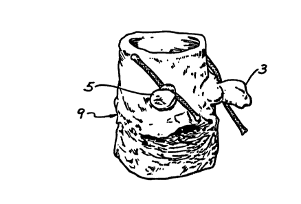
FIGURE 1 is a view of the aortic 6egment before
trimming.
FIGURE 2 ie ~ view of the aortic segment with
cylindrical ~u~o~s inserted into the leaflets preparatory
to t~ g.
FIGURE 3 is a view of the stentless aortic valve from
the in-flow 6ide showing the Du~u~&ble cloth covering along
the inflow rim and the ~urface of the right coronary ~eptal
~helf.
FIGURE 4 is a view of the ~tentless aortic valve from
the out-flow side showing the ~ able cloth co~ering
along the
pseudoannulus _nd coronary artery openings.
FIGURE 5 is a top view of the holder body.
~f g ~ U ~
_ FIGURE 6 i~ a ~ide view of the holder body and
detachable h~n~le.
FIGURE 7 is a perepective view of the ~tentless aortic
valve showing the ~older ~ody with handle att~
S ~uspended within the inflow orifice of the valve.
A D~ ON OF THE ~r~KK~v EMBODIMENTS
The ~tentle~ heart valve herein is prepared by
securing a portion of an animal aortic root, preferably
porcine, including the intact aortic valve. As 6hown in
Figure 1, the etumps of the left and right coronary
arteries 3 and 5, respectively, are tied off and only
minimal trimming to remove ~ess fat and loo~e ti~sue is
done to prevent distortion of aortic root 9 during
fixation. The valve is preferably tanned according to the
low pressure method described in U.S. Patent 4,372,743,
which is incorporated herein by reference in its entirety.
The t~nning ~olution i8 preferably glutaraldehyde, most
preferably a buffered eolution ~uch as 0.625% Hepes
buffered glutaraldehyde.
Although low pressure tAn~ing can be conducted at
pressures up to 20 mm Hg, it has been found that maximum
flexibility is retained when the pressure i6 maintained
below about 10 mm Hg, most preferably about 2 mm Hg. As
shown in Figure 2, cylindrical inserts 2 are inserted into
the leaflets of the aortic ~egment 4 during the tAnning
process to maintain the natural unstressed 6hape of the
valve.
After tAnning~ the valve i~ 6terilized by 6ubmerging
it in a biocompatible ~terilizing 601ution, preferably one
that helps to reduce calcification. For instance an
agueous ~olution buffered with ~epes and containing 4.0
percent formaldehyde, 22 percent ethanol, 1.2 percent Tween
~- 10
- 80 (FETH), or a ~imilar ~olution buffered with phocphate
(FETS) can be u6ed. Then the prosthetic valve is sized
using caliper6 to determine its out~ide diameter, ~ Ally
ro~nd~ off to the nearest ~illimeter. For commercial
application6, a valve whose out~ide diameter does not ~o~.d
off to an odd number ~etween 15 ~nd 27, inclu6ively, is
~-r--~lly re~ected.
After ~izing the valve6 are ~ub~ected to a ~econd
trimming ~tep ~n which cub~tantially all of the myocardial
tissue i8 shaved away, leaving a thin cartilage rim
adjacent to the right coronary septal ~helf for
reinforcement. The left and right coronary arteries are
cut out following the ~-c~ ann~lAr line but leaving eno~gh
tissue to protect the commi6sures. Preferably the cut is
made 80 that about 2 to 4 mm of t~-F'l~ remains from the
edge of the hole to the pseudo-~nn~lA~ line, and about 3 to
5 mm of tis~ue remain~ between the hole edge and the
commissures. All trimming i6 conducted with the goal of
leaving an intact band of aorta about 2 to 5 mm in width
above the two coronary oren;nqs 47. The intact band of
aorta is necess~ry to maintain proper alignment of the
commissures and prevent distortion of the valves during
suturing.
Finally, the inflow rim is trimmed on the ~ame plane
as the cusps of the leaflets, usually leaving an intact
segment of about 3 to 4 mm in width a~ measured from the
hinge of the leaflet. All of the fatty tissue in the aorta
i~ trimmed away.
As 6hown in Figure 3, the resulting aortic ~egment
contains three valve leaflet~, each of which is affixed to
the aortic ~egment at a ~uncture. Aortic valve 13, excised
from a porcine heart, includes a tubular aortic 6egment of
the ascending aorta 19 and three valve leaflets 21, 23, and
; ll
2~3~5~
_ 25. The bulk of the ~yocardial t~ ? has been trimmed
from valve 13 to ~inimize distortion during $ixation, and
the coron~ry arteries (not shown) have been cut out as
above described. Adjacent ~dge~ of the valve leaflets
21,23, and 25 ~eet to form eommi~sures 27 at the ~unctions
between adjacent valve leaflets. Each of the valve
leaflet~ 21, 23 and 25 can be con~idered a~ ~oined to
~rcenAing aorta 19 along a ~uncture 29. The wall of the
~cenA;ng aorta 19 adjacent ~ ~u~e 29 form~ ~n"re~ of
Valsalva (not ~hown). Valve leaflet 21, the right coronary
leaflet, iB positioned ~omewhat asymmetrically with ~ ect
to the other two leaflets.
The cloth covering i8 made of any ~mooth, thin
biocompatible material D L. ~ly ~no--7h to hold sutures, but
is preferably of white dacron, ~uch as that manufactured by
Bard Cardiosurgery Division, C. R. Bard, Inc. under part
no. 6103, having a thic~ne~s of .008 ~c~es and a weight of
72 grams per ~quare meter. The cloth is cut on the
diagonal to assure a snug fit around ~Lved surfaces,
cleaned to remove contaminants such as dirt and lint,
preferably by submerging in Freon for 60 ~econ~, and
sterilized.
As shown in Figure 3, at the inflow end the entire
right coronary septal shelf 33 is covered externally by a
piece of cloth 32 stitched into place, preferably by hand,
using a nondi~solvable biocompatible thread and
whipstitches 35 at the thin rim adjacent to the right
coronary septal ~helf 37. The inflow rim 39 is covered,
preferably starting at the ~u..e~u-e of the left and
noncoronary cusps 41, by a piece of cloth 32 folded at the
half-width ~o that approximately 2.S mm. of cloth extends
on each side of the fold. The rim to be covered is placed
within the fold. Therefore, the cloth covering extends
12
SJ1~
~long the inflow rim, both internally and externally, and
along the exterior curface of the entire right coronary
~eptal ~helf. Preferably this ~egment of cloth i~ a ~ingle
piece.
s
~ arking~ 43, for example, ~titches ~n a ~G..L.~sting
color of thread, are located on the cloth curface along the
inflow rim, preferably at the ~id-cusp point of each
leaflet, to ~id the ~u~eG~ in ~ligning the valve within
the patient's natural aorta. For in~tance, if the cloth is
white, the marking can be ctitches of navy blue threAd, ~nd
the like. An exemplary light green marking thread is
Polyester Teflon Coated Polydek, ~ize 6.0, having a denier
of 110-130 manufa~L~ed by Dekatel C~o~ation, Queens
Village, New York.
As ~hown in Figure 4, at the outflow ~ide, cloth 32 is
sewn only on the internal portion of the valve. Surgeons
use the coverings on the outflow ~ide of the valve as an
anchor and a ~Lule guide, ~o they must be placed far
enough from the leaflets to pose no risk of placing a
suture through the leaflet and thus damaging or rendering
the valve incompetent. Two pieces of cloth are required,
cut diagonally by laser to about 2 to 4 mm, preferably
about 2.5 to 3.5 mm in width, to run along and match the
shape of edge of the coronary artery openings. The length
of these pieceC of cloth is determined by the reguirement
that about 1 to 4 mm, prefer~bly about 2.5 to 3.0 mm of
~pace, must be left between each end of the cloth and the
nearest commi~ure 48.
As ~hown in detail in Figure 4, at outflow rim 46
cloth 32 i~ sewn to cover the area running internally
directly along the pseudoannulus 45 of the valve and over
the cutouts for both the right and left coronary arteries
~3
47, but the ~L~ e cribed ~-~o~ered np~le is left
L~/aen the edges of the cloth and each valve commi6sure.
The cloth covering thu~ giveQ ~u~v~L to an area commonly
known in the art a~ the -~con~ .~L~e line and provide~
secure ~un~ for the ~u~eo.. to place the ~econd
line.
The cloth piece~ are permanently attached to the
aortic ~egment by stitch~g them into place w~th fine
~titches, preferably by hand, u~ing ~ ~n~ olvable
biocompatible thread. Preferably one edge of the cloth is
cecured by a line of in-and-out ~titches 51 about 0.5 mm in
length placed immediately above the ~ s~nnulus line
utilizing Teflon thread ~uch as that manufa~L~ed by W. L.
Gore and ~crocjAteC~ Inc., Elkton, MD., having a denier of
200-250, monofilament zero twi t (Part ~ YlD162 PTFE). The
other edge of the cloth i8 ~u~led to the hole edge with
whipstitches 53 ~n~ng along the inside of the coronary
open;n~s using the ~ame piece of Teflon thread, while
making sure that the cloth is fluuh with the hole edge.
Although the valve holder body can be of any cize and
shape ~uitable to be ~ecured adjacent to the aortic 6egment
and made of a biocompatible substance, valve holder body 55
preferably comprises two cylindrical ~egments extruded from
a biocompatible plastic ~uch as transparent polysulfone
thermoplastic ~old by Union Carbide Co~oL&tion as part
P 1700-11, having a tensile yield ~trength of 9,500 psi
min. Preferably the holder body is ~ized to fit within
the ~en;~g of the aortic ~egment.
As ~hown in Figures 5 and 6, a first cylindrical
~egment 57 of valve holder body 55 has axis 59 and is
hollow, having an internal diameter of from about 3.5 mm to
6.5 mm, and an external diameter of from about 5 mm to 10
~ . ~ ~
14 2~ 51~
- mm, ~ost preferably about 7 Ym, and a length of from about
4 mm to 16 mm, Dost preferably about 6 ~m. Joined
thereto and ~oaY~ al ly aligned therewith i6 -eCOnA
eylindrieal ~egment 61 having an external diameter of from
S about 8 D to 13 ~m, ~o~t preferably ~bout lO mm, and
length of from about 2 D to 8 D, ~ost preferably ~bout 4
mm. A ~oaYially aligned eylindrieal d~ ion 63 extends
into eylindrieal ~egment 61 for a depth egual to about one
half the length of the ~egment. The diameter of
eylindrieal ~ ion C3 i~ egual to the internal diameter
of fir~t eylindrieal ~egment 57. Therefore, with fir~t and
Aecon~ eylindrieal ~egments ~oined, the interior wall of
eylindrieal 6egment 57 and eylindrieal depression 63 define
eylindrieal ~pace 65, the ~ides of whieh have threads (not
~hown) for receiving the threaded end 69 of ~n~le 71.
uAn~le 71 i~ a eylindrieal rod ~ized to fit into
eylindrieal spaee 65 by means of threads at end 69 ~o that
handle 71 ean be ~lewe-l into valve holder body 55. Holes
80 extend through eylindrieal ~egment 61 to provide a means
for attaching the holder body to the prosthetie aortic
valve.
Any of a number of Deans ean be used for detachably
eonnecting the holder body to the heart valve so long as
they do not eompromise the integrity of the leaflets. The
preferred means for attaching the holder body to an aortic
prosthesis i~ ~hown in Figure 7. From one to about six,
most preferably four, loose ~uture threads 81 are threaded
through holes 80 provided in the holder body as well as
eompletely through the wall of the outflow ~ide of the
aortie segment 55, preferably through the tissue above the
openings for the eoronary arteries 47. The ~uture threads
are then fastened (i.e. tied) as shown in Figure 7 ~o that
the holder body hangs ~uspended within the 6aid outflow
opening. This ~imple Deans of attaehment ean readily be
2 ~ ~ ~ J .~ ~
snipped by the surgeon and the holder body and BULULe~ can
be removed once the first suture line h~s been placed, or
at ~ny time during the surgical implant ~ re.
As an ~dditional advantage, the band of aortic segment
on the outflow ~ide of the valve optionally can be trimmed
to fit the needs of the part~ r patient and/or the
likings of the surgeon. For instance the outflow ~ide of
the valve can be trimmed ~o as to completely remove the
portion of the aortic band ~xt~n~ ng between the outflow
rim and the coronary artery openings. Trimming the
flexible prosthetic valve in this way does not de_L~oy its
natural shape or function.
Although exemplary embodiments of the invention have
been shown and described, many changes, modifications and
substitutions may be made by one having ordinary skill in
the art without nec~6s~rily departing from the spirit and
scope of the invention described and claimed herein.