Note: Descriptions are shown in the official language in which they were submitted.
2~6S7.~
INSTRUMENT FOR INSERTING A PROTECTIVE SLEEVE
INTO THE MEDULLARY CANAL OF A BONE
This invention relates to surgical instrumentation
for implanting a protective sleeve for a bone ~oint
replacement prosthesis and, more particularly, an instrument
for in3erting a protective sleeve into the medullary canal of
a bone.
During surgical implantation of, for example, a toe
or finger prostheses, it is typically necessary to utilize a
protective sleeve on the prostheses stems. Prostheses
designed for use with protective sleeves include a thickened
mid-section and are fabricated from a flexible elastomeric,
physiologically inert material, such as a cured silicone
rubber, that is susceptible to lacerations and tearing at the
stems which can lead to premature failure of the prostheses.
The sleeves shield the prostheses stems from shearing caused
by sharp bone edges of the resected bone of the medullary
canal believed to be responsible for lacerations and tearing.
The prostheses stems generally correspond to the
dimension of the medullary canal of the bones ad~acent the
prostheses thickened midsection and are implantable within
the canal. Prior to implantation of the stem, one sleeve is
surgically implanted within the medullary canal of the bone
ad~acent the thickened midsection before the stem is
implanted into the medullary canal.
The above procedure requires an accurate press-
fitting of the sleeve into the medullary canal.
There remains a need for an instrument that can
accurately insert the sleeve into the medullary canal without
bending, scratching or distorting the sleeve.
In accordance with the present invention, an
instrument for surgically implanting a protective sleeve for
2~`~6574
--2--
a flexible bone ~oint replacement prostheses is provided.
The instrument comprises a handle having a central axis with
opposed proximal and distal ends, wherein the distal end of
the handle is configured with a first connection portion. A
head having opposed proximal and distal portions, includes a
base extending axially from the distal portion. The proximal
portion of the head is configured with a second connection
portion for mating engagement with the first connection
portion of the handle. A post protrudes distally from the
base and includes a cross-section which is tapered in a
distal direction from a thicker portion at the intersection
of the post with the base. The taper of the post is adapted
for mating with the protective sleeve to be press-fitted into
the medullary canal of a bone. Means are provided for
removably securing the head to the handle.
The invention may be better appreciated by
reference to the attached Drawings, which illustrate one or
more preferred embodiments, wherein:
YIG. 1 is a per~pective exploded isometric view of
the instrument showing the handle, head and a protective
sleeve to be inserted, according to the invention;
YIG. 2 is a cross sectional view of the head taken
substantially along lines Z-2 of YIG. l;
FIG. 3 is a perspective view showing the protective
sleeve of FIG. l;
FIG. 4 is a perspective view showing a prostheses
which is intended to cooperate with the sleeve of FIG. 3;
FIG. 5 is a perspective view showing the prostheses
of YIG. 4 with the protective sleeves as they would be in
place on the stem portions of the prostheses;
YIG. 6 is a perspective view showing the prostheses
and protective sleeves implanted in the medullary canals of
adjoining bones of a finger ~oint;
2~3~
FIG. 7 i~ a perspective view showing one stem
portion of the prostheses implanted in the medullary canal of
an ad~oining bone of a ~oint and a protective sleeve
press-fit into the medullary canal of the other adjoining
bone;
FIG. 8 is a perspective view showing a protective
sleeve being implanted into the medullary;
YIG. 9 is a perspective exploded isometric view of
the instrument showing the handle having a threaded portion,
head and a protective sleeve to be inserted, according to the
invention;
YIG. 10 is a cross-sectional view of the head taken
substantially along lines 10-10 of FIG. 9; and
FIG. 11 is a perspective view showing the insert
that is to be press-fitted into the head of FIG. 10.
Further ob~ects and advantages can be appreciated
by reference to the ensuing Detailed Description, taken in
con~unction with the above-mentioned Drawings, wherein the
reference numerals are used to designate corresponding
structures of the Drawings.
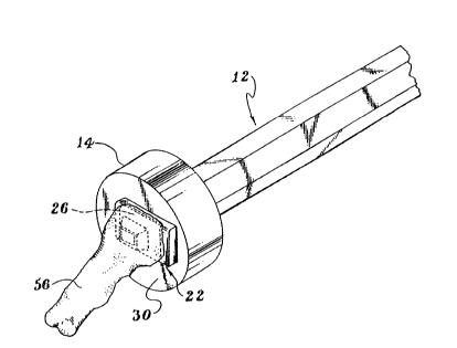
Referring to YIG. 1, a preferred embodiment of an
instrument for inserting a protective sleeve, such as a
grommet, is generally shown at 10. The instrument 10
comprises an elongated handle, generally indicated at 12,
having a central axis and a head which is indicated at 14.
Handle 12, preferably made of stainless steel, further
includes opposed proximal 16 and distal 18 ends, distal end
18 being configured with a first connection portion 20 for
interconnecting the handle and head 14 with one another. The
head 14 includes a base 22 with a protruding post 24 adapted
for receiving grommet 26 to be implanted into the medullary
canal. Means are further provided for removably securing
2~3~ 7'~
head 14 to handle 12, as will be described in more detail
below.
As shown in more detail with reference to FIGS. 1
and 2, head 14 has opposed proximal 28 and distal 30
portions, with base 22 extending axially from the distal
portion. The proximal portion 28 is configured with a second
connection portion 32 for mating with first connection
portion 20 of handle 12, wherein head 14 and the handle are
removably interconnected. Head 14 is formed from a high
density TEFLON~ or other material which is nonabrasive to a
prostheses or grommet being implanted and is sized to be
interchangeable, allowing a single handle to be used with
different head sizes corresponding to different grommet
sizes.
Referring in more detail to YIGS. 1-3, base 22 is
generally rectangular in cros9-section, corresponding to
rectangular flanged section 34 of grommet 26, shown in FIG.
3. Base 22 supports grommet 26 and distributes the forces
exerted during press-fitting of the grommet into the
medullary canal 50, to flanged section 34, reducing the risk
of bending the grontmet. Base 22 further includes horizontal
leading edge 36 having radiu~ R adapted for mating with
radius flanged section 38 also having a radius r, of
implantsble grommet 26.
Referring to FIGS. 2, 3 and 8, post 24 protrudes
distally from base 22 and includes a cross-section tapered in
a distal direction from a thicker portion 40 at the
intersection of the post with the base. The tapered
cross-section of post 24 is configured to mate with
protrusion 42 of grommet 26 as the grommet is situated on the
post for implantation. It should be understood that the
length of post 24 is dependent on the size of the particular
implant and of sufficient length to hold grommet 26 on the
2C,`S~- ,'4
--5--
post. Grommet 26 i9 of the type conventionally used in
finger and toe ~oint replacement surgery. A further detailed
description of the structure and use of the grommet may be
found in U.S. Patent No. 4,158,893 issued June 26, 1979.
Referring to YIGS. 9, 10 and 11, the means for
securing head 14 to handle 12 preferably takes the form of
thread portion 43 formed in first connection portion 20 of
handle 12 which is threaded into second connection portion 32
via insert 45. Insert 45, preferably made of stainless
steel, further having internal threads 47 is press-fitted
into second connecting portion 32 to threadedly interconnect
head 14 and handle 12. The structure for head 14 and grommet
16 are the same as YIGS. 1-3 with the exception of the above
reference numbers.
Referring to FIGS. 1 and 2, in an alternate
embodiment, the means for securing head 14 to handle 12 takes
the form of ball plunger arrangement 44 formed in first
connection portion 20 of handle 12, which is retained in a
pilot hole 46 formed in head 14. First connection portion 20
including ball plunger arrangement 44 is in~erted into second
connection portion 32 formed in the proximal portion 28 of
base 22. With the first connection portion 20 inserted in
second connection portion 32, handle 12 is rotated until the
ball plunger arrangement 44 engages pilot hole 46 to
interconnect head 14 and the handle. Head 14 is easily
disconnected from handle 12 by further rotating the handle
until ball plunger arrangement 44 disengages pilot hole 46.
A surgeon-can quickly interchange different head sizes to
correspond with different grommet sizes used during surgery
while using the same handle.
The grommet 26 (FIG. 3) and prostheses 48, (YIGS.
4-7) are implanted into the prepared medullary canal 50 of
bone 56 surgically as follows. The canal 50 is first drilled
2 ~ ~ ~'j'7~
and reamed as shown in phantom in FIG. 6, the reaming
corresponding to the dimensions of stems 52, 54 of prostheses
48. After prostheses 48 is implanted into the prepared
canals 50, grommets 26 are situated over stems 52, 54 (YIGS.
5-7). Grommet 26 protects stems 52 and 54 from lacerations
that may occur from sharp edges of bones adjacent the
medullary canal 50. Lacerations of stems 52 and 54 are
believed to be the starting point of tears, which could
ultimately lead to premature joint failure.
Referring to ~IG. 8, grommet 26 is shown situated
on post 24 of base 22 and aligned with horizontal leading
edge 36 of the base. With grommet 26 situated on post 24,
the surgeon then press-fits the grommet into canal 50.
It may be appreciated that the present invention
may be used with a variety of prostheses having projecting
stems and requiring the use of a protective sleeve.
These and other variations of the present invention
may be made which fall within the scope of the appended
claims even though such variations were not specifically
discussed above.