Note: Descriptions are shown in the official language in which they were submitted.
91- ~ -017
_ 1 ~086867
ENHANCED AUTOMATED SPLITTER SHIFTING CONTROL
BACKGROUND OF THE INVENTION
Field of the Invention
The present invention relates to a control
system or method for controlling the auxiliary section
splitter actuator of an automated or partially automated
vehicular compound transmission. In particular, the
present invention relates to a control system or method
for controlling the splitter section actuator of an
automated or partially automated compound vehicular
transmission wherein a two-position fluid actuated
actuator is utilized to engage and disengage
non-synchronized jaw clutches to selectively engage
either a low-speed or a high-speed splitter section
ratio.
DescriPtion of the Prior Art
Compound change gear transmissions of the type
having one or more auxiliary sections connected in
series with a main transmission section are very well
known in the prior art. Such transmissions are
typically associated with heavy duty vehicles such as
large trucks, tractor/semi-trailers, and the like.
Auxiliary transmission sections are of three general
types; range type, splitter type, or combined
range/splitter type.
In compound transmissions having a splitter
type auxiliary section, the ratio steps of the splitter
auxiliary section are less than the ratio steps of the
main transmission section and each main transmission
section ratio may be split, or subdivided, by the
splitter section. E~amples of compound change gear
2~86867
transmissions having splitter type auxiliary sections may
be seen by reference to U.S. Patent Nos. 4,290,515;
3,799,002; and 4,527,447.
In a combined range and splitter type auxiliary
section, or sections, both range and splitter type
ratios are provided allowing the main transmission to be
progressively shifted through its ratios in at least two
ranges and also allowing the main transmission section
ratios to be split in at least one range. Examples of
compound transmissions having a single combined
range/splitter type auxiliary section may be seen by
reference to U.S. Patent Nos. 3,283,613; 3,648,546 and
4,754,665. Assignees well known RT/RTO 11613 and RT/RTO
14718 "Eaton Roadranger"~ transmissions are examples of
combined range/splitter type transmissions.
77~
Another example is the "Ecosplit~ model of
transmission sold by Zahnradfabrik Friedrichshafen
Aktiengeseushaft of Friedrichshafen, Germany which is a
sixteen forward speed type of transmission which
utilizes a separate two-speed splitter auxiliary section
in front of and a separate two-speed range section
behind the main transmission section.
It should be noted that the terms main and
auxiliary sections are relative and that~the
designations of the main and auxiliary sections are
reversed, the type of auxiliary section (either range or
splitter) will also be reversed. In other words, given
what is conventionally considered to be a four speed
main section with a two-speed range type auxiliary
section, if the normally designated auxiliary is
considered the main section, then the normally
~.'.~'
3 2086867
designated main section would be considered a four speed
splitter type auxiliary section therefor. By generally
accepted transmission industry convention, and as used
in this description of the invention, the main
transmission section of a compound transmission is that
section which contains the largest (or at least no less)
number of forward speed ratios, which allow selection of
a neutral position, which contains the reverse ratio(s)
and/or which is shifted (in manual or semi-automatic
transmissions) by manipulation of the shift bar or shift
rail or shift shaft/shift finger assembly as opposed to
master/slave valve/cylinder arrangements or the like.
Splitter shift control systems and methods for
controlling the fully or partially automated shifting of
splitter section nonsynchronized jaw clutches in
automated or partially automated compound transmissions
are known in the prior art. An example of such a
partially automated transmission system may be seen by
reference to U.S. Patent No. 4,722,248. Such prior art
automated or partially automated transmissions, especially
those utilizing a two-speed splitter section wherein
either a low-speed or a high-speed splitter ratio could be
selected, utilized a fluid pressure operated differential
area piston actuator wherein the smaller piston surface
area is constantly pressurized to urge the actuator to
cause engagement of the low-speed splitter section ratio
and the actuator chamber associated with the larger area
piston face is selectively pressurized or exhausted to
cause engagement or disengagement of the high-speed
splitter section ratio.
The splitter section control systems/methods of the
prior art was not totally satisfactory as shifts
A~
.~
2086867
_ - 4 -
were occasionally noisy due to splitter clutch raking,
in cold weather conditions disengagement of the
low-speed splitter clutch was difficult as the full
force generated by the larger piston surface was not
available and, in the event of a failure of the
electricity to the solenoid controllers, the splitter
section would automatically default to the low-speed
ratio thereof regardless of the intention of the
operator.
SUMMARY OF THE INVENTION
In accordance with the present invention, the
drawbacks of the prior art are minimized or overcome by
the provision of a control system/method for controlling
automated splitter shifting in a fully or partially
automated compound transmission which will reduce
splitter clutch raking, will minimize missed shifts in
cold temperatures, will provide potentially longer
splitter clutch life and, upon an electrical failure of
the controlling solenoid(s) will allow the splitter
clutch to remain engaged in its current splitter section
gear ratio.
The above is accomplished by providing
individually controllable valves, preferably solenoid
controlled valves, for selectively controlling the
pressurization and exhausting of the actuator cylinder
chambers associated with both the smaller area piston
surface and the larger area piston surface of a two
position differential area piston actuator.
Accordingly, during a splitter shift transient, upon
sensing that the actuator is in a nonengaged position,
which will result from attempts to engage the splitter
clutch at significantly nonsynchronous rotation, the
control allows both chambers of the actuator to be
~ ~ 5 ~ 2086867
exhausted until substantially synchronous rotation of
the engaging clutch is sensed thus reducing raking of
the splitter clutch jaw teeth. Preferably, the
appropriate cylinder will be repressurized as the jaw
clutch approaches synchronous to allow a rapid and
smooth engagement of the splitter jaw clutch.
Additionally, in cold weather conditions, a relatively
higher force may be utilized to disengage the low-speed
splitter jaw clutch and to engage the high-speed
splitter clutch by pressurizing the actuator chamber
associated with the large area piston face while
retaining the other chamber vented. Further, each of
the valves controlling the chambers is preferably biased
to a exhausting position whereby an electrical failure
of the controlling solenoids will result in the solenoid
controlled valves exhausting both chambers allowing the
splitter clutch to remain in its currently engaged
ratio.
Accordingly, the present invention provides a new
and improved control system/method for controlling the
automated splitter shifting of a fully or partially
automated compound transmission.
This and other advantages of the present invention
will become apparent from a reading of the detailed
description of the preferred embodiment taken in
connection with the attached drawings.
~RIEF DESCRIPTION OF THE DRAWINGS
Figure l is a schematic illustration of a
partially automated mechanical transmission system
having partially automated splitter section shiftingO
Figure lA is a schematic illustration of a
transmission for use in the system of Figure l and being
b
2086867
-
a compound transmission having a combined range and
splitter type auxiliary section.
Figure lB is a schematic illustration of the
semi-automatic shift pattern for the transmission system
of Figure l.
Figure 2 is a schematic illustration of a prior
art splitter shifting control system.
Figure 3 is a schematic illustration of the
automated splitter shift control system of the present
invention.
DESCRIPTION OF THE PREFERRED EMBODIMENT
Certain terminology will be used in the
following description for convenience and reference only
and will not be limiting. The words "upwardly",
"downwardly", "rightwardly~ and "leftwardly" will
designate directions in the drawings to which reference
is made. The words "forward", "rearward", will refer
respectively to the front and rear ends of the
transmission as conventionally mounted in a vehicle,
being respectfully from left and right sides of the
transmission as illustrated in Figure l. The words
"inwardly", and "outwardly", refer to directions towards
and away from, respectively, the geometric center of the
device and designated parts thereof. The above applies
25 to the words above specifically mentioned, derivatives
thereof and words of similar import.
The term "compound transmission" is used to
designate a change speed or change gear transmission
having a multiple forward speed main transmission
30 section and at least one multiple speed auxiliary
transmission section connected in series whereby the
selected gear reduction in the main transmission section
may be compounded by further selected gear reduction in
- 7 - 2086867
the auxiliary transmission section. "Synchronized
clutch assembly" and words of similar import shall
designate a positive, jaw-type clutch assembly utilized
to nonrotatably couple a selected gear to a shaft by
means of a positive clutch in which attempted engagement
of said clutch is prevented until the members of the
clutch are at substantially synchronous rotation and
relatively large capacity friction means are utilized
with the clutch members and are sufficient, upon
initiation of a clutch engagement, to cause the clutch
members and all members rotating therewith to rotate at
substantially synchronous speed.
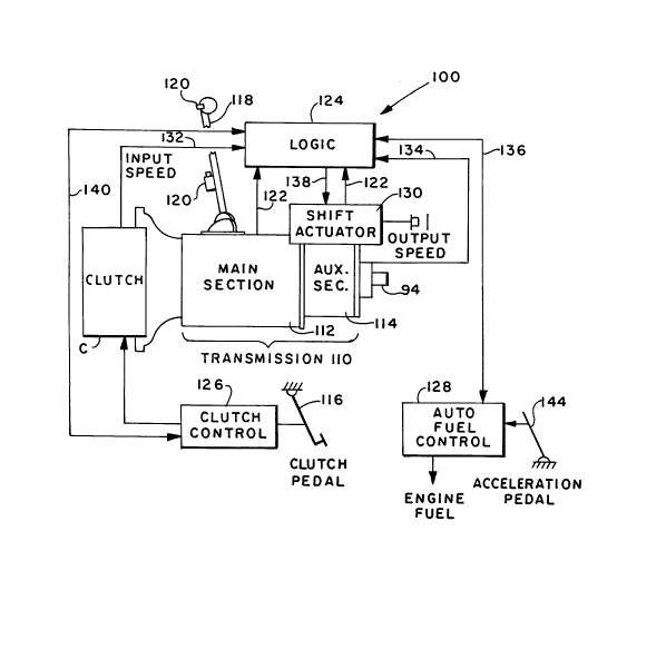
Figure 1 illustrates a partially automated
transmission system 100 having a compound transmission
110 with a main section 112 connected in series with an
auxiliary section 114 of the combined range and splitter
type. In the high-speed main section and high-speed
range section position (i.e. the 11th and 12th speed
position), splitter shifting between 11th and 12th
speeds is automated. An e~ample of this type of
transmission system may be seen by reference to U.S.
Patent No. 4,722,248.
Compound type transmission 110 comprises a main
section 112 coupled to an auxiliary section 114 is
controlled by the splitter shift control system and
method of the invention. Main section 112 is
operatively coupled to the drive shaft 20 of the vehicle
engine 112 by clutch C and output shaft 94 of the
auxiliary section is operatively coupled, commonly by
means of a drive shaft, to the drive wheels of the
vehicle (not shown).
The change gear ratios available from
transmission 110 are manually selectable by first
A.~
2086867
depressing clutch pedal 116 to disengage the engine
drive shaft and then positioning shift lever 118
according to the shift pattern prescribed to engage the
particular change gear ratio of main section desired and
thence, in the event the particular gear ratio desired
is contained within a different ratio of auxiliary
section 114, by operation of one or more actuators such
as electrical shift button or fluid actuating valves 12Q
to provide a signal operative to effect the engagement
within auxiliary section 114 desired as is well known to
those skilled in the operation of compound type
transmissions.
For the purpose of this invention, the term
"group" as used herein shall mean the particular
plurality of gear ratios available from a vehicular
transmission and particularly from a compound type
transmission when a particular gear ratio is manually
selected by an operator and the term "sequentially
related" as used herein shall mean between gear ratios
available within the group selected provided there is no
intervening gear ratio available within another group
such as, for example, shown in group ~Auto" of Figure lB
where automatic shifting is effected between gear ratios
11 and 12 but not between gear ratio 4 and 11 or 12
since other groups contain gear ratios intermediate to
gear ratios 4 and gear ratios 11 and 12. Generally, the
transmission is of the type having a plurality of
forward gear ratios of which one group selectable by the
operator is sequentially related and less than the total
number of gear ratios provided by the transmission and
automatic shifting is effected between at least two of
the sequentially related gear ratios.
In the system 100, preferably, all of the gear
ratios except the highest and those sequentially related
~ - 9 - 2086867
to the highest in the group including the highest gear
ratio, are manually selectable by the operator by
actuating button 120 if required (i.e. to preselect) and
then depressing clutch pedal 116 to cause clutch C to
disengage transmission 112 from the engine drive member
and then position shift lever 118 and thence, upon
engagement of the desired change gear ratio, release
pedal 116.
The shift control system is operative to
initiate and enable automatic shifting between at least
the sequentially related gear ratios within the highest
group and preferably between all sequentially related
gear ratios within each group whenever the lowest gear
ratio included within the group is selected by the
operator.
The control system of the invention includes
means for sensing and providing a suitable signals 122
to means operative to enable automatic shifting at the
particular gear position desired. The means operative
to enable automatic shifting includes logic circuitry
124, clutch control 126, auto fuel control 128 and shift
actuator 130. Logic circuitry 124 is operative to
receive and operate upon information including input
speed signal 132, gear ratio position signals 122,
output speed signals 134 and accelerator pedal position
signal 136 to initiate and provide automatic shifting as
required. Generally, automatic shifting is accomplished
by shift actuator 130 including valves, actuators and
the like well known to those skilled in the art
according to the nature of a signal 138 received from
logic circuitry 124 which, in turn, provides signal 140
to clutch control 126 which in turn provides signal 142
for automatic operation of clutch C in coordination with
providing and receiving a signal 126 to automatic fuel
2086867
,_ -- 1 0 --
control 128 relative manual operation of accelerator
pedal 144 in addition to information concerning output
speed of output shaft 94 provided logic circuitry 16 by
signal 134.
The above described means by which automatic
shifting is effected is well known to those skilled in
the art excepting that it becomes operable only when a
gear ratio included in at least the group including the
highest gear ratio is manually engaged by the operator.
Examples of such automatic shifting may be appreciated
in greater detail by reference to U.S. Patent Nos.
4,361,060; 4,527,447; and 3,478,851.
Logic circuitry 124 is preferably in the form of a
microprocessor based controller, or ECU, as described in
U.S. Patent No. 4,595,986.
Although the present invention is described in
connection with the partially automated system of Figure
1, it is also useful in connection with more fully
automated systems such as the type described in U.S.
Patent No. 4,361,060.
The structure of a compound transmission 110
hàving a combined range and splitter type auxiliary
section 114 may be seen in Figure lA. Referring now to
Figure lA, there is a schematically illustrated a well
known and highly commercially successful thirteen-speed
compound transmission 110. Transmission 110 comprises a
main transmission section 112 connected in series with
an auxiliary transmission section 114 having both range
and splitter type gearing. Typically, transmission 110
is housed within a single housing and includes an input
shaft 16 driven by a prime mover such as diesel engine E
R
11- 2086867
through a selectively disengaged, normally engaged
friction master clutch C having an input or driving
section 18 drivingly connected to the engine crank shaft
20 and a driven portion 22 rotatably fixed to the
transmission input shaft 16.
In the main transmission section 112, the input
shaft 16 carries an input gear 24 for simultaneously
driving a plurality of substantially identical main
section countershaft assemblies 26 and 26a at
substantially identical rotational speeds. In the
transmission 10 illustrated, two substantially identical
main section countershaft assemblies are provided on
diametrically opposite sides of a mainshaft 28, which
mainshaft is generally coaxially aligned with the input
shaft 16. Each of the main section countershaft
assemblies 26 and 26a comprises a main section
countershaft 30 supported by bearings 32 and 34 in
housing H, only a portion of which is schematically
illustrated. Each of the main section countershafts 30
is provided with an identical grouping of main section
countershaft gears 38, 40, 42, 44, 46 and 48, fixed for
rotation therewith. A plurality of main section drive
or mainshaft gears 50, 52, 54, 56 and 58 surround the
mainshaft 28 and are selectively clutchable, one at a
time, to the mainshaft 28 for rotation therewith by
sliding clutch collars 60, 62 and 64 as is well known in
the art. Clutch collar 60 may also be utilized to
clutch input gear 24 to mainshaft 28 to provide a direct
drive relationship between input shaft 16 and mainshaft
28. Preferably, each of the main section mainshaft
gears encircles the mainshaft 28 and is continuous
meshing engagement with and is floatingly supported by
the associated countershaft gear group, which mounting
means and a special advantages resulting therefrom are
~ 12 - 2086867
explained in greater detail in U.S. Patent Nos. 3,105,395
and 3,335,616. Typically, clutch
collars 60, 62 and 64 are axially positioned by means of
shift forks (not illustrated) associated with a shift
bar housing assembly (not illustrated) as well known in
the prior art. Clutch collars 60, 62 and 64 are axially
positioned by means of shift forks (not illustrated) as
well known in the prior art. Clutch collars 60, 62 and
64 are of the well known nonsynchronized double acting
jaw clutch type.
It is understood that although transmission llO
is illustrated as of the well known and commercially
successful multiple identical countershaft, floating
mainshaft and floating mainshift gear type, and while
the auxiliary transmission section of the present
invention is particularly well suited for such
transmission structure, the advantages of the present
invention are equally applicable to transmissions of the
single countershaft or nonidentical multiple
countershaft type.
Main section mainshaft gear 58 is the reverse
gear and is in continuous meshing engagement with
countershaft gears 48 by means of conventional
intermediate idler gears (not shown). It should also be
noted that while main transmission section 12 does
provide five selectable forward speed ratios, the lowest
forward speed ratio, namely, that ratio provided by
drivingly connected mainshaft drive gear 56 to mainshaft
2~, is often of such a high gear reduction as to ~e
considered a low or "creeper~' gear which is utilized
only for starting of a vehicle under severe conditions
and is usually not utilized in the high transmission
range and/or may not be split in the low transmission
A~
-
- 13 - 2 08 6867
range. Accordingly, while the main section 12
illustrated does provide five forward speeds, it is
usually referred to as a "4+1" main section as only four
of the forward speeds are compounded by the auxiliary
transmission section 14.
Jaw clutches 60, 62 and 64 are three-position
clutches in that they may be positioned in a centered,
nonengaged position as illustrated or in a fully
rightwardly engaged or fully leftwardly engaged position.
Auxiliary transmission section 114 is connected
in series with main transmission section 112 and is of
the three-layer, three-speed combined range/splitter
type. Mainshaft 28 extends into the auxiliary section
14 and carries an auxiliary drive gear 70 fixed thereto,
which auxiliary drive gear simultaneously drives a
plurality of auxiliary section countershaft assemblies
72 and 72A at equal rotational speeds. Each of the
auxiliary countershaft assemblies, 72 and 72A, comprises
an auxiliary countershaft 74 supported by bearings 76
and 78 in housing H and carrying three auxiliary section
countershaft gears 80, 82 and 84 fixed for rotation
therewith. Auxiliary section countershaft gears 80 are
constantly meshed with auxiliary drive gear 70 while
auxiliary section coun'ershaft gears 82 and 84,
respectively, are constantly meshed with auxiliary
driven gears 86 and 88, respectively. Auxiliary section
~ driven gear 86 coaxially surrounds stub shaft 90 which
is coaxial with mainshaft 28 and carries a synchronized
sliding two-position synchronized clutch assembly 92
thereon. Auxiliary section driven gear 88 coaxially
surrounds output shaft 94 which carries a two position
slidable jaw clutch collar 96 thereon, which jaw clutch
collar is substantially structurally and functionally
identical to jaw clutch collars 60, 62 and 64 utilized
- 14 - 20~6867
in the main transmission section 12. Clutch assemblies
92 and 96 are both two position clutch assemblies, which
may be selectively located in the rightwardmost or
leftwardmost axial positions, but not normally in a
centered nonengaged position therebetween. Typically,
clutch assemblies 92 and 96 are axially positioned in a
selected axial position by means of shift forks
positioned by a remotely controlled fluid actuated
piston assembly as is well known in the prior art.
Synchronized clutch assembly 92 may be removed
to the leftwardmost position to drivingly couple
auxiliary drive gear 70 and mainshaft 28 to auxiliary
stub shaft 90 or may be selectively axially positioned
in the rightwardmost position to selectively
rotationally couple auxiliary driven gear 86 to
auxiliary stub shaft 90. Sliding clutch collar 96 may
be axially positioned in the leftwardmost position to
rotationally couple stub shaft 90 to output shaft 94 or
may be axially positioned in a rightwardmost position to
rotationally couple auxiliary drive gear 88 to output
shaft 94.
Auxiliary section countershaft gears 80 and
auxiliary section drive gear 70 comprise a first gear
layer, auxiliary section countershaft gears 82 and
auxiliary section driven gear 86 comprise a second gear
layer and auxiliary countershaft gears 84 and auxiliary
section driven gear 88 comprise a third gear layer of
the three gear layer auxiliary transmission section 14.
As may be appreciàted, when clutch collar 96 is in the
rightwardmost position drivingly coupling auxiliary
driven gear 88 to output shaft 94, mainshaft 28 will
drive the output shaft 94 through auxiliary drive gear
70, auxiliary countershaft gear 80, auxiliary
countershaft gear 84 and auxiliary drive gear 88
_ 15 - 2086867
regardless of the position of synchronized clutch
assembly 92 and thus the three-gear-layer au~iliary
transmission section 14 provides a maximum of three
selectable ratios.
Synchronized clutch assembly 92 is the range
shift clutch utilized for ma~ing range shifts in the
auxiliary section while sliding jaw clutch collar 96 8is
the splitter clutch utilized for making splitter shifts
in the auxiliary section. A shift ork 96A is utilized
to selectively axially position nonsynchronized jaw
clutch collar 96.
Further structural details of transmission 110
and the splitter clutch 96 may be seen by reference to
U.S. Patent Nos. 4,754,665; 4,788,889 and 4,964,313.
A prior art control system 160 for controlling
the automated shifting of a two-speed splitter section
is illustrated in Figure 2. Axial positioning of
splitter jaw clutch collar 96 is by means of shift fork
or yoke 96A associated with a pneumatically operated
differential area piston/cylinder actuator assembly 162.
Assembly 162 defines a cylinder housing 164 in
which is sealingly and slidably received a differential
area piston 166 having a first smaller surface area face
168 and an opposed second larger surface area face 170.
Piston 166 divides the cylinder into a first chamber
168A associated with the first face and a second chamber
170A associated with the second face.
Pressurization of chamber 168A will develop a
force urging shift fork 96A leftwardly to engage the
low-speed splitter ratio while pressurization of chamber
170A will develop a force urging shift fork 96A
rightwardly to engage the high-speed splitter ratio.
A '~r'
_ _
- 16 - 2 0 8 6 8 67
Conduit 172 constantly connects low-speed
chamber 168A to a source of pressurized air from the air
supply 174 (often an onboard compressor and/or wet tank)
and the filter/regulator assembly 176. In heavy duty
vehicles, the pressurized air to the transmission and
other actuators is typically regulated to 60 to 80 psi.
Chamber 170A is connected to conduit 178 which
fluidly connects high-speed chamber 170A to a three way
two position valve 180 which is biased to connect
conduit 178 to exhaust and is selectively movable to a
position connecting conduit 178 to filtered and
regulated source of pressurized air. Valve 180 may be
selectively operated by a valve actuator 182, such as a
solenoid actuated valve, in response to command output
signals from the controller 124.
In operation, first chamber 168A is constantly
pressurized and urges the low-speed splitter jaw clutch
into engagement with a first force. To engage the
high-speed splitter clutch, valve 180 is caused to
assume its pressurizing or second position to pressurize
the second chamber, high-speed chamber 170A, and the
high-speed splitter jaw clutch will be urged into
engagement with a force equal to the product of the
pressurization of the regulated air times the difference
in area between the second (170) and first (168) piston
faces.
In a particular example, the surface area of
first face 168 is about 1.11 square inches (Al=l.ll
in ), the surface area of second face 170 is about
2.46 square inches (A2=2.46 in2) and the regulated
pressure is 60 psi (Ps=60 psi). Accordingly, the force
generated by pressurizing the first face is about 66.4
lbs to the left, the force generated by pressurizing the
second face is about 147.7 lbs to the right and the
- 17 - 2 08 68 67
force generated by pressurizing both faces is about 81.3
lbs. to the right. Thus, when valve 180 is in the
normal or exhausting position, the splitter sleeve 96 is
urged into engagement with the low-speed splitter ratio
(direct in Figure lA) with about 66.4 lbs. of force, and
when valve 180 is in the pressurizing position, splitter
clutch sleeve 96 is urged rightwardly into engagement of
the high-speed splitter ratio (overdrive in Figure lA)
with about 81.3 lbs. of force.
The prior art control system of Figure 2 is
generally effective, however, in certain circumstances,
improvement is desirable. As chamber 168A is constantly
pressurized, the clutch sleeve 96 is constantly urged
either leftwardly of rightwardly and thus, even if
substantial nonsynchronous conditions at the engaging
jaw clutch teeth is sensed, the clutch teeth will be
urged into raking engagement causing possibly
objectionable noisy splitter shift and/or wear of the
clutch teeth. Also, after clutch engagement a constant
force is continuously applied to clutch sleeve which may
result in wear and/or stress to the shifting elements.
Further, in the case of an electrical failure to valve
actuator 182, the splitter section will default to the
low-speed position thereof which may be contrary to the
vehicle operator's wishes.
Additionally, as chamber 168A is constantly
pressurized, the full available force (about 147.7 lbs.)
provided by pressurizing chamber 170A is not available
for high force disengagement of the low-speed ratio
and/or engagement of the high-speed splitter ratio as
may be desirable under certain conditions such as cold
weather operation of system 100.
The control system 200 of the present invention
for automatic shifting a two-speed splitter section is
_ - 18 ~ 2086867
illustrated in Figure 3. As with the prior art system
160, a two-position, differential area piston actuator
162 is utilized to position the splitter clutch 96, and
pressurized air is provided by the supply 174 and
filter/regulator 176.
The system controller, ECU 124, operates on
various inputs from the fuel controller, an actuator
position sensor 201 and the speed sensors to issue
command output signals to the fuel controller and two
control valves, 202 and 204.
Valves 202 and 204 are each two-position,
three-way valves for connecting a controlled port, 202A
and 204A respectively, to either the source of regulated
air or to exhaust. Valves 202 and 204 are independently
operable with valve 202 controlling the pressurization
or exhaust of actuator chamber 168A and valve 204
controlling the pressurization or exhaust of actuator
chamber 170A. Preferably, as illustrated in Figure 3,
valves 202 and 204 are solenoid controlled valves biased
to the exhausting positions thereof. As the valves are
independently operable, each of the two actuator
chambers 168A and 170A are independently and
individually pressurized or exhausted and, in the event
of an electrical power failure, neither of the chambers
will be pressurized which might cause the actuator to
assume a possibly undesirable default position thereof.
The operation of system 200 is as described
below.
For an upshift sequence, the shift sequence
starts when the controller 124 had determined that a
shift point has been reached. Shift point selection is
based upon multiple inputs to the controller and may be
based upon logic such as is utilized in above-mentioned
U.S. Patent No. 4,361,060. As this is an upshift, both
~ - 19 - 2086867
the low 202 and the high 204 speed solenoid control
valves are energized. As a result of the differential
area piston, this provides a net force on the splitter
clutch towards the high-speed splitter ratio position.
At the same time, the fuel controller is caused to
decrease fueling of the engine causing a torque break.
When a torque break occurs, the splitter clutch 96 will
succumb to the net force in the high-speed ratio
direction which will disengage the splitter clutch from
the low-speed ratio. Since the splitter clutch is
driven by a two position piston/cylinder actuator 162,
the splitter clutch is driven across neutral, towards
engagement with the high-speed jaw clutch. However, as
there is usually such a high initial differential speed
between the engaging jaw clutch members, the sliding
splitter clutch member is rejected by the clutch member
rotating with the high-speed ratio gear and very little
raking of the jaw clutch teeth occurs. As the system
detects that the splitter clutch has gone to the neutral
position by means of position sensor 201, both solenoid
valves 202 and 204 are turned off to reduce the force of
a splitter clutch to zero. The splitter clutch now
"floats" in the neutral region, waiting for synchronous
speed to be achieved.
Simultaneously, as soon as splitter neutral is
detected, the automatic fuel control is operated in a
synchronizing mode to cause the engine speed to be
brought to synchronous with the desired gear, preferably
via a closed loop control. As the engine speed is
approaching synchronous, based upon the rate of
approaching synchronous and the clutch actuator reaction
time, the high-speed ratio solenoid valve 204 is
energized by itself to supply full force for engagement
of the splitter clutch into the high-speed ratio
- - 20 - 2086867
.~
position. This helps assure that full jaw clutch
engagement is obtained. Once the system has determined
that the splitter has fully engaged, fueling of the
engine is returned to operator control. Preferably, the
high-speed solenoid control valve 204 remains energized
for a sufficient amount of time (about 2 seconds) to
assure continued engagement of the high-speed ratio jaw
clutch. The solenoids are then deenergized to increase
the reliability of the solenoids and drive circuitry.
The downshift operational sequence of control
system 200 is similar to the upshift sequence described
above except that only the low-speed solenoid control
valve 202 is energized to drive the splitter clutch into
neutral and then into the low-speed splitter operational
position. It is important to note that the
disengagement force required on the downshift is much
less due to the lower torque-lock effect holding the
gears engaged. Therefore, the pneumatic actuator
piston/cylinder is designed to have the lower force when
shifting from high speed to low speed (i.e.
downshifting) and the higher force when shifting from
low speed to high speed (i.e. upshifting).
The above system also allows for a full force
splitter shifting control algorithm which is most useful
during a shift into the high-speed splitter ratio in
cold temperatures (less than 30 degress Fahrenheit) when
the splitter clutch resistance to-disengagement of the
low-speed ratio is extremely high. By independently
controlling the high-speed ratio cylinder 204, the full
force of pressurized fluid acting on piston face 170 may
be utilized to disengage the splitter clutch from the
low-speed position thereof.
Briefly, during an upshift when both solenoid
control valves have been actuated, if, for a given
- 21 - 2086867
period of time (about 1.0 to 2.0 seconds) after
decreasing fuel, a disengagement of the low-speed
splitter ratio is not sensed, the low-speed solenoid 202
is deenergized while the high-speed solenoid 204 remains
energized thus applying maximum force for disengagement
of the low-speed ratio. At the same time, the fuel
controller is caused to increase then decrease the
fueling of the engine to create another torque break
across the splitter section. During a downshift,
although the force applied to the splitter clutch cannot
be increased, if disengagement of the high-speed ratio
is not sensed within a predetermined period of time,
(usually about one to two seconds) the engine fuel
controller is again cause to momentarily increase and
then again decrease the fueling of the engine to create
a torque break across the engaged splitter jaw clutches.
Upon sensing completion of a desired shift for
a predetermined period of time, as indicated above, all
solenoids are deenergized to increase the life and
reliability of the solenoids, the actuators and the
drivers. To assure continued engagement, the
appropriate solenoid may be periodically energized
(every 20 - 60 seconds) for a short period of time (1.0
to 2.0 seconds) to assure complete and continued
engagement of the desired splitter speed jaw clutch.
As indicated previously, as both of the
solenoid controlled valves 202 and 204 are biased to the
exhaust positions thereof, an electrical failure will
simply cause the valves to move to, or remain in, the
exhausting position thereof and thus allow the splitter
clutch to remain in its as is position.
Although this invention has been described in
its preferred form with a certain degree of
particularity, it is understood that the present
~ - 22 _ 20~6867
disclosure of the preferred embodiment has been made
only by way of example, and that numerous changes in the
detailed construction and combination and arrangement of
the parts may be resorted to without departing from the
spirit and the scope of the invention, as hereinafter
claimed.