Language selection

Search

Patent 2087094 Summary

Third-party information liability

Some of the information on this Web page has been provided by external sources. The Government of Canada is not responsible for the accuracy, reliability or currency of the information supplied by external sources. Users wishing to rely upon this information should consult directly with the source of the information. Content provided by external sources is not subject to official languages, privacy and accessibility requirements.

Claims and Abstract availability

Any discrepancies in the text and image of the Claims and Abstract are due to differing posting times. Text of the Claims and Abstract are posted:

  • At the time the application is open to public inspection;
  • At the time of issue of the patent (grant).
(12) Patent: (11) CA 2087094
(54) English Title: TORSION SPRING AND ADJUSTABLE MOUNTING FOR A CHAIR USING SUCH A SPRING
(54) French Title: RESSORT DE TORSION ET DISPOSITIF DE FIXATION POUR FAUTEUIL UTILISANT CE RESSORT
Status: Deemed expired
Bibliographic Data
Abstracts

English Abstract


ABSTRACT

Straight type torsion spring being clamped
together at two ends, which ends being rotatable in
relation to each other against the torsion spring force,
the torsion spring comprising at least four identical
torsion rods abutting laterally along their entire
extension, thereby utilizing the relatively large twisting
angle of the small dimension torsion rods combined with the
total torsion force of the torsion spring rods, each of
which independently being twisted helically when activating
the spring. Adjustable mounting for a chair, preferably an
office chair, comprising the torsion spring of the above
defined type, a seat frame, a back frame and a mounting
bracket, a tilting lever being clamped to a pipe which
other end is clamped to one end of the torsion spring, the
upper end of the lever being articulated to the front
portion of a seat frame, the rear portion of which being
articulated to a back seat frame to which rear end the back
seat is secured, and the forward end of the back seat frame
being articulated to the bracket, the position of which
articulation being adjustable thereby enabling an
adjustment of the back seat frame angle.


Claims

Note: Claims are shown in the official language in which they were submitted.

Amended claims

THE EMBODIMENTS OF THE INVENTION IN WHICH AN EXCLUSIVE
PROPERTY OR PRIVILEGE IS CLAIMED ARE DEFINED AS FOLLOWS:-
1. Adjustable mounting for a chair, preferably an
office chair, comprising the torsion spring comprising a seat
frame (1), a back frame (2) and a mounting bracket (3), CHARAC-
TERIZED IN a tilting lever (9) being clamped to one end of a pipe
to which other end is clamped one end of a torsion spring (5)
comprising four torsion spring rods, all of which being clamped
together, the upper end of the lever (9) being articulated to the
front portion of a seat frame (1), the rear portion of which
being articulated to a back seat frame (2) to which rear end the
back seat is secured, and the forward end of the back seat frame
(2) being articulated to the bracket (3), to which bracket (3)
also the second end of the torsion spring (5) is secured, the
position of the seat frame articulation (12) on the bracket (3)
being adjustable thereby enabling an adjustment of the back seat
frame angle.
2. Mounting according to claim 1, CHARACTERIZED IN a
stop pin (6) being fixed to the mounting bracket (3), limiting
the rotation movement of the lever (9) between two outermost
positions in which the pin (6) abuts shoulders on the lever (9).
3. Mounting according to claims 1-2, CHARACTERIZED IN
a torsion spring according to claim 1 being mounted in the
articulation (11) between the seat frame (2) and the back seat
frame (29, thereby distributing desired torsion forces between
the torsion spring at the front and the torsion spring at the
rear of the seat.


Description

Note: Descriptions are shown in the official language in which they were submitted.


W~92/03072 2 o ~ 7 o 9 ~ PCT/NO90/001~

TORSION SPRING AND ADJUSTABLE MOUNTING FOR A CHAIR USING SUCH A
SPRING. -~

The present ivention is related to a torsion spring and
s an adjustable mounting for a chair according to the preamble of
the claims.
Mountings for chairs and specially office chairs
generally provides for possibility to adjust the inclination of
the seat and the position of the back as well, independently or
lO not. The height of the seat usua ly is adjusted with the position
of the mounting on a central column or the position of the column
in a base device.
Mountings of the above mentioned type normally comprise
a spring function, thereby making it possible for the user to
tilt the back o the chair, the seat ot both. Additionally the
use may adjust the height and the angles of the seat and the back
to a compfortable position for the user.
For designing such chairs as such it is advantagous
that the mounting as such is small thereby giving more freedom
2Q to design work, also of cosmetic reasons, as a mounting with
smaller dimensions easily may be hidden behind the seat. ~-
The torsion spring according to the present invention
provides a spring having smaller dimensions as compared to known
torsion springs having the same spring force and twisting angle. , ~
25The adjustable mounting according to the present -
invention provides an special motion picture as compared to knwon
mountings as a combination with the way of articulating the seat,
the back and the mounting bracket. A very comfortable chair is
achieved which easily may be adjusted to a desired angle for the
30 back seat and the seat. This advantages are achieved with the
torsion spring and the mounting according to the present
invention as deined by the features stated in the claims.
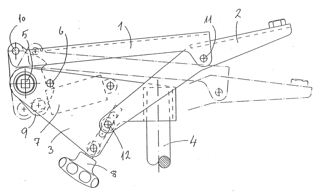
The only Figure discloses a side view of the adjustable
mounting, disclosing also the position of the seat and the back
35 frames in a relaxed position of the chair.
The drawing discloses a mounting bracket 3 fixed to a
center shaft 4 which connection may be adjustable in the height,
whereby the center shaft 4 is fixed to a not disclosed base as

W O 92/03072 PC~r/N O90/00134
2 2087~
well known in the art.
It has been discovered that the spring function of a
torsion spring may be substantially increased when the torsion
spriny instead of only one bar comprises at least four rods, all
s being clamped together at the ends of the spring.
Principally the spring effect of a torsion spring will
increase with the spring bar cross section dimension. When
increasing the cross section, however, the twisting angle will
be limited. Torsion springs having small dimensions make poss~ble
~0 larger twisting angles, but will naturally be correspondingly
weaker, e.g. the spring force is decreased.
It is, however found that a combination of a plurality
of smaller torsion rods give the desired high spring force,
thereby substantially maintaining a relatively large twisting
S angle, as each of the rods will be twisted separately in a
helically line.
The friction forces between the single rods in a multi
rod torsion spring to a certain degree also contribute to
increase the spring force in relation to one single bar having
20 a cross section corresponding to the total cross section of all
rods. The result of the combined effect from torsion forces of
the small dimension rods and the friction forcès; result in the
spring force being achieved with a certain total spring cross
section of substantially shorter spring length than is the case
25 with a single rod torsion spring having the same cross section,
the torsion spring comprising several single rods, thereby
maintaining a desired, relatively large twisting angle.
A torsion spring 5 of the above disclosed type is
disclosed in the drawing, arranged in a mounting bracket 3. In
30 the middle between the two side walls of the bracket 3 a tilting
,~ lever 9 is clamped to a pipe which other end ist clamped~to one
end of the torsion spring 5. A second pipe is connected to the
other end of the torsion spring 5, the other end of the pipe
being connected to a lever against which a screw connected with
35 the brackett 3 is adJustable.
To the upper end of the lever 9 the front portion of a
seat frame 1 is articulated. The lever 9 preferably comprises
abutments limiting the rotation angle of the lever 9 to a desired

~ ' . '

~? 92/03~72 PCT/NO90/00134
3 208709~
amount, by means of a stop pin 6 connected ~ith the bracket 3 for
- limiting the rotation angle in two outermost positions.
The rear portion of the seat frame 1 is articulated to
a ~ack frame 2, the rear end of which is connected to the back
s seat and the front end of which being connected to the bracket
3. Preferably the connection between the back frame 2 and the
bracket 3 is adjustable by means of an adjustable knob 8 thereby
making a change possible of the point around which the back frame
2 is rotating, to achieve a desired angle of the back seat,
10 adapted to the user, in the upright position as well as in the
relaxed position.
The distance between the torsion spring 5 and the
articulation 10 between the lever 9 and the seat frame 1 as well
as the possible rotation angle ~or the lever 9, limited by the
15 stop pin 6, may be such that it is comfortable for the user when
pressing the back seat backwards, the front end of the seat frame
1 thereby simultaneously being moved backwards to achieve a
better position and an angle for the knees when in the relaxed
position.
Furthermore the position of the articulation 11 between
the seat frame 1 and the back f~ame 2 may be such that the
distance between the articulation 11 and the articulation 12
between the back seat frame 2 and the bracket 3 as well as the
distance between the torsion spring 5 and the articulation 12,
25 provide a suitable inclination of the back seat which is rigidly
connected with the back seat frame 2, in the raised position as
well as in the relaxed position.
A dampening and locking device 7 is arranged within the
bracket 3, connecting the lever 9 to the bracket such as by a
30 gas spring 7. Suitably this connection by be one end of the lever
9 opposite the articulation 10.
The well known gas springs used in similar chairs do
not provide for the possibility of adjusting the spring force.
Gas springs, however, have the advantage of small physical
35 dimensions with the benefit of freedom for the chair designer.
An advantagous combination of small spring dimensions and
adjustment possibility is however achieved with the chair
according to the present invention, comprising the inventive
muliti rod torsion spring.


,~.. ,, ,. ,., i,, ... ,. .;, . , .. ,. , . .,, ., ". , . , . , . ... , , ,, , , ", ,, - ,

Representative Drawing
A single figure which represents the drawing illustrating the invention.
Administrative Status

For a clearer understanding of the status of the application/patent presented on this page, the site Disclaimer , as well as the definitions for Patent , Administrative Status , Maintenance Fee  and Payment History  should be consulted.

Administrative Status

Title Date
Forecasted Issue Date 1993-12-14
(86) PCT Filing Date 1990-08-20
(87) PCT Publication Date 1992-02-21
(85) National Entry 1993-01-11
Examination Requested 1993-01-11
(45) Issued 1993-12-14
Deemed Expired 2008-08-20

Abandonment History

There is no abandonment history.

Payment History

Fee Type Anniversary Year Due Date Amount Paid Paid Date
Application Fee $0.00 1993-01-11
Maintenance Fee - Application - New Act 2 1992-08-20 $50.00 1993-01-11
Registration of a document - section 124 $0.00 1993-07-13
Maintenance Fee - Application - New Act 3 1993-08-20 $50.00 1993-08-19
Maintenance Fee - Patent - New Act 4 1994-08-22 $50.00 1994-08-19
Maintenance Fee - Patent - New Act 5 1995-08-21 $75.00 1995-07-27
Maintenance Fee - Patent - New Act 6 1996-08-20 $75.00 1996-08-20
Maintenance Fee - Patent - New Act 7 1997-08-20 $75.00 1997-07-17
Maintenance Fee - Patent - New Act 8 1998-08-20 $75.00 1998-07-20
Maintenance Fee - Patent - New Act 9 1999-08-20 $150.00 1999-07-19
Maintenance Fee - Patent - New Act 10 2000-08-21 $200.00 2000-07-31
Maintenance Fee - Patent - New Act 11 2001-08-20 $200.00 2001-07-09
Maintenance Fee - Patent - New Act 12 2002-08-20 $200.00 2002-07-15
Maintenance Fee - Patent - New Act 13 2003-08-20 $200.00 2003-07-03
Maintenance Fee - Patent - New Act 14 2004-08-20 $250.00 2004-08-12
Maintenance Fee - Patent - New Act 15 2005-08-22 $450.00 2005-07-12
Maintenance Fee - Patent - New Act 16 2006-08-21 $450.00 2006-07-21
Expired 2019 - Corrective payment/Section 78.6 $1,475.00 2007-01-25
Owners on Record

Note: Records showing the ownership history in alphabetical order.

Current Owners on Record
RING MEKANIKK A.S.
Past Owners on Record
LIE, TORE
Past Owners that do not appear in the "Owners on Record" listing will appear in other documentation within the application.
Documents

To view selected files, please enter reCAPTCHA code :


To view images, click a link in the Document Description column. To download the documents, select one or more checkboxes in the first column and then click the "Download Selected in PDF format (Zip Archive)" or the "Download Selected as Single PDF" button.

List of published and non-published patent-specific documents on the CPD .

If you have any difficulty accessing content, you can call the Client Service Centre at 1-866-997-1936 or send them an e-mail at CIPO Client Service Centre.


Document
Description 
Date
(yyyy-mm-dd) 
Number of pages   Size of Image (KB) 
Representative Drawing 1999-05-07 1 19
Cover Page 1997-11-02 1 87
Abstract 1997-11-02 1 59
Claims 1997-11-02 1 56
Drawings 1997-11-02 1 46
Description 1997-11-02 3 248
Fees 1997-07-17 1 44
Fees 1998-07-20 1 46
International Preliminary Examination Report 1993-01-11 11 423
Office Letter 1993-03-26 1 27
Prosecution Correspondence 1993-09-22 2 46
Prosecution-Amendment 2007-01-25 2 52
Correspondence 2007-03-08 1 12
Fees 1996-08-20 1 40
Fees 1993-07-27 1 41
Fees 1994-08-19 1 43
Fees 1993-08-19 1 31
Fees 1993-01-11 1 46
Fees 1993-07-20 1 26