Language selection

Search

Patent 2087293 Summary

Third-party information liability

Some of the information on this Web page has been provided by external sources. The Government of Canada is not responsible for the accuracy, reliability or currency of the information supplied by external sources. Users wishing to rely upon this information should consult directly with the source of the information. Content provided by external sources is not subject to official languages, privacy and accessibility requirements.

Claims and Abstract availability

Any discrepancies in the text and image of the Claims and Abstract are due to differing posting times. Text of the Claims and Abstract are posted:

  • At the time the application is open to public inspection;
  • At the time of issue of the patent (grant).
(12) Patent Application: (11) CA 2087293
(54) English Title: DRIVESHAFT WITH SLIP JOINT SEAL
(54) French Title: LIGNE D'ARBRE AVEC GARNITURE A JOINT COULISSANT
Status: Dead
Bibliographic Data
(51) International Patent Classification (IPC):
  • F16C 3/02 (2006.01)
  • F16D 3/06 (2006.01)
  • F16D 3/84 (2006.01)
  • F16J 15/32 (2006.01)
(72) Inventors :
  • BURTON, ROBERT A. (United States of America)
(73) Owners :
  • BURTON, ROBERT A. (United States of America)
(71) Applicants :
(74) Agent:
(74) Associate agent:
(45) Issued:
(22) Filed Date: 1993-01-14
(41) Open to Public Inspection: 1993-10-07
Availability of licence: N/A
(25) Language of filing: English

Patent Cooperation Treaty (PCT): No

(30) Application Priority Data:
Application No. Country/Territory Date
07/864,307 United States of America 1992-04-06

Abstracts

English Abstract


ABSTRACT OF THE DISCLOSURE
A slip joint seal for a driveshaft is between two universal
joint yokes. A male splined shaft rotates with a first yoke and
a female splined shaft rotates with a second yoke, with the two
being mechanically engaged for slidable but nonrotational
movement during operation of the driveshaft. A sealing sleeve
extends from the first yoke around the male splined shaft and
is of a larger diameter than the female splined shaft. The
female splined shaft has a first outwardly-facing, annular
seal at its outer end, away from the second yoke, which seal
engages the inner surface of the sealing sleeve. A propeller
shaft is affixed to the end of the female splined shaft toward
the second yoke and to the second yoke, preferably being of the
same diameter as the sleeve. A second annular seal which is
the same size and the first one is carried by an end of the
male splined shaft beyond the female shaft. The second seal
engages the inner surface of the propeller shaft. The female
splined shaft also has a grease fitting for supplying grease
to the shafts between the two annular seals. Splines and
grooves of the male and female shafts are designed to enable
grease to readily move past them.

-18-


Claims

Note: Claims are shown in the official language in which they were submitted.


I CLAIM:
1. A driveshaft comprising a first universal joint yoke,
a second universal joint yoke spaced at a varying distance from
said first universal joint yoke when said driveshaft is in
operation, a first shaft extending rearwardly of said first
universal joint yoke and rotatable therewith, a second shaft
extending rearwardly of said second universal joint yoke and
rotatable therewith, said shafts being in mechanical engagement
for all operating positions of said first and said second
universal joint yokes to enable slidable but nonrotatable
movement between said shafts, means closing off an end portion
of said second shaft closer to said second universal joint yoke,
a sleeve extending rearwardly of said first universal joint yoke
and extending over at least a substantial portion of said first
shaft, and having a diameter greater than an outer diameter of
said second shaft, said sleeve extending around said first shaft
and around an end portion of said second shaft away from said
second universal joint yoke and having an open end away from
said first universal joint yoke, a first resilient seal carried
by the end portion of said second shaft away from said second
yoke, said seal having an annular lip facing outwardly and
slanted toward said second universal joint yoke, said lip
engaging an inner surface of said sleeve for all operating
positions of said first and said second universal joint yokes,
said lip enabling grease in an annular chamber formed between
said first shaft and said sleeve to pass by said seal toward
the open end of said sleeve, said lip serving to wipe contaminants
off the inner surface of said sleeve when said first and said

-11-

second universal joint yokes move away from one another, said
second shaft having an annular recess at the end toward said
second universal joint yoke, a cylindrical member with an
annular groove affixed to an end of said first shaft beyond
said second shaft toward said second universal joint yoke, a
tubular member connecting said second shaft and said second
universal joint yoke, and a second resilient seal in said
annular groove of said cylindrical member and engaging the
inner surface of said tubular member for all operating positions
of said first and said second universal joint yokes, and a grease
fitting in said second shaft spaced toward said second universal
joint yoke from said seal.

2. A driveshaft according to claim 1 wherein said sleeve
and said tubular member have the same diameter.

3. A driveshaft according to claim 2 wherein said first
resilient seal and said second resilient seal have lips with
the same maximum diameters.
4 A driveshaft according to claim 1 wherein said first
shaft has external splines and said second shaft has internal
splines which are in mechanical engagement for all operating
positions of said first and said second universal joint yokes.
5. A driveshaft according to claim 4 wherein said splines
of each of said shafts engage grooves of the other of said shafts
and stop short of the bottoms of the grooves to provide grease
passages therebetween.

-12-

6. A driveshaft comprising a first universal joint yoke,
a second universal joint yoke spaced at a varying distance from
said first universal joint yoke when said driveshaft is in
operation, a male splined shaft extending rearwardly of said
first universal joint yoke and rotatable therewith, a female
splined shaft extending rearwardly of said second universal
joint yoke and rotatable therewith, said male and said female
splined shafts being in mechanical engagement for all operating
positions of said first and said second universal joint yokes,
a cylindrical sleeve extending rearwardly of said first
universal joint yoke and having a diameter greater than an
outer diameter of said female splined shaft, said sleeve
extending around said male splined shaft and around an end
portion of said female splined shaft away from said second
universal joint yoke for all operating positions of said
driveshaft, said sleeve having an open end away from said
first universal joint yoke, said female splined shaft having
an outwardly-facing, annular groove at the end portion away
from said second universal joint yoke, a first seal, said
seal having a base band under tension in said groove and
having an annular lip extending outwardly, said lip engaging
an inner surface of said sleeve for all operating positions of
said driveshaft, said lip serving to wipe contaminants off the
inner surface of said sleeve when said first and said second
universal joint yokes move away from one another, said female
splined shaft having an annular recess at the end toward said
second universal joint yoke and beyond internal splines therein,
a tubular member connecting said second shaft and said second

-13-

universal joint yoke, and a second seal affixed to an end of
said first shaft beyond said second shaft toward said second
universal joint yoke, said second seal engaging the inner
surface of said tubular member for all operating positions
of said first and said second universal joint yokes.

7. A driveshaft according to claim 6 wherein said sleeve
and said tubular member have the same diameter.
8. A driveshaft according to claim 7 wherein said first
resilient seal and said second resilient seal have lips with the
same maximum diameters.
9. A driveshaft according to claim 6 wherein said first
shaft has external splines and said second shaft has internal
splines which are in mechanical engagement for all operating
positions of said first and said second universal joint yokes.
10, A driveshaft according to claim 9 wherein said splines
of each of said shafts engage grooves of the other of said shafts
and stop short of the bottoms of the grooves to provide grease
passages therebetween.

-14-

11. A driveshaft comprising a first universal joint yoke,
a second universal joint yoke spaced at a varying distance from
said first universal joint yoke when said driveshaft is in
operation, a male splined shaft extending rearwardly of said
first universal joint yoke and rotatable therewith, a female
splined shaft extending rearwardly of said second universal
joint yoke and rotatable therewith, said male and said female
splined shafts being in mechanical engagement for all operating
positions of said first and said second universal joint yokes,
a sleeve extending rearwardly of said first universal joint yoke
and rotatable therewith, said sleeve having a diameter greater
than an outer diameter of said female splined shaft and extending
around an end portion of said female splined shaft away from
said second universal joint for all positions of said first and
said second universal joint yokes, a first resilient seal
carried by the end portion of said female splined shaft away
from said second yoke, said seal engaging an inner surface of
said sleeve for all operating positions of said first and
said second universal joint yokes, a tubular member connecting
said second shaft and said second universal joint yoke, and a
second resilient seal carried at the end of said first shaft
and engaging the inner surface of said tubular member for all
operating positions of said universal joint yoke.

12. A driveshaft according to claim 11 wherein a grease
fitting is in said female splined shaft spaced toward said
second universal joint yoke from said first seal.

-15-

13. A driveshaft according to claim 11 wherein said first
seal has an annular lip extending outwardly and slanted toward
said second universal joint yoke, said lip serving to wipe
contaminants off the inner surface of said sleeve when said
first and said second universal joint yokes move away from
one another.

14. A driveshaft according to claim 11 wherein said second
seal has an annular lip extending outwardly and slanted toward
said first universal joint yoke.
15. A driveshaft according to claim 13 wherein said second
seal has an annular lip extending outwardly and slanted toward
said first universal joint yoke.

16. A driveshaft according to claim 11 wherein said sleeve
and said tubular member have the same diameter.
17. A driveshaft according to claim 16 wherein said first
resilient seal and said second resilient seal have lips with
the same maximum diameters.

18. A driveshaft according to claim 11 wherein said first
shaft has external splines and said second shaft has internal
splines which are in mechanical engagement for all operating
positions of said first and said second universal joint yokes.

-16-


19. A driveshaft according to claim 18 wherein said splines
of each of said shafts engage grooves of the other of said shafts
and stop short of the bottoms of the grooves to provide grease
passages therebetween.

20, A driveshaft according to claim 12 wherein said female
splined shaft has a smooth cylindrical recess facing inwardly
at the end toward said second universal joint yoke, said grease
fitting communicating with said cylindrical recess.

-17-

Description

Note: Descriptions are shown in the official language in which they were submitted.


~ Y~ ~ 9 ~3
J ~ -


This invention relates to a slip jolnt grease s~al for
driveshaEt.


Slip jOillt seals have been long known in the ar~. 'Ihe
05 slip joint comprises male and emale splined shafts which
connect between two universal joint yokes, They are rotatably
connected but can slide relative to one anoiher to accommodate
differences in length of the driveshaft during operation.
Various seals have been employed to maintain grease between
-~hé splined shafts. With one common type of seal heretofore
employed, the male splined shaEt is exposed to the elements
when the universal joints are at extended positions, wlth
contaminants, including water, then being carried back between
the two shafts as the driveshaEt contracts. Other seals have
been overly complex, and inef~icient and/or tend to wear out
relatively quickly.


The seal in accordance with the invention is used with
a slip joint which is between two universal joint yokes in a
driveshaft which contracts and extends during operation of
a vehicle with which it is used. A males splined shaft extends
rearwardly from a first universal joint yokes and rotates
therewi-th, ~ female splined shaft extends rearwardly of a
second universal joint yoke, rotates therewith, and is mechani-


cally engaged for slidable but nonrotatable movement with themale splined sha~t for all positions o~ the driveshaft and the
yokes. A sealing sleeve extends rearwardly of the first
universal joint yoke and rotates therewith, being suitably


-2-

2 ~ ~ r~J ~ 9 3

affixed thereto, 'I'he sealing sleeve has an outer di~meter
exceeding the o~ter diallleter Or the female splined shaft
which extends into an annular chamber formed between the
male splined shaft and the se~ling sleeve. The female splined
05 shaft carries an outwardly-facing, annular sealing ring in a
groove, at its outer end away from the second universal joint
yoke. The sealing ring includes a base band under tension in
the groove, wi-th an outwardly-extending lip slanting toward the
second universal joint yoke and engagable with the inner
I0 surface of the sealing sleeve for all operational positions
of the two universal joint yokes. The slanted lip enables
excess grease in the annular chamber to pass by it and be
expelled through an outer open end of the sleeve beyond the
seal, The slan-ted lip also acts as a wiper to remove con-

taminants, including moisture, from the inner surface o thesealing sleeve when the driveshaft moves toward an extended
position.


The female splined shaft has an inner annular recess at
an end portion -toward the second universal joint yoke and beyolld
the internal splines thereof. ~ grease fit-ting is also carried
by the female splined shaft, preferably communicating with the
annular recess between the internal splines and the end of the
shat. A propeller shaft or tubular member also is af-fixed to
the same end portion of the female splined shaft and to the
second universal joint yoke. The propeller shaft and the sealing
sleeve preferably are of the same diameter to reduce the number
of different components required to be carried in inventory.


~ ~ ~ r~ 3 ~


The length of the sealing sleeve, the propeller shaft, and the
male splined shaft can be v~ried according to the particular
requirements.


05 The end of tlle male splined shaft toward the second universa,
joint yoke extends beyond the female splined shaft for all
operational positions of the two universal joint yokes. It
carries a piston which is suitably af~ixed to the end of the
male splined shaft, as by a machine screw. The piston has a
groove in which is carried a second sea]ing ring of the same
size and shape as the first one. It includes a base band under
tension in the groove with an outwardly-extending li~ slanted
toward the first universal joint yoke9 in this instance, and
engagable with the inner surface of the propeller shaft for all
lS operating positions.


With the first sealing ring being affixed to the female
splined shaft and the second sealing ring being affixed to the
male splined shaft, the space containing grease remains under
substantially constant volume as the universal joint yokes and
the splined shafts move toward and away from one another, This
space includes tlle annular chamber between the male splined
shaft and the sealing sleeve and, at the other end, between the
male splined shaft and propeller shaft.

The size and shape of the splines and grooves of the male
and female splined shaft are designed such that space exists

between the bottoms of the grooves and the peaks of the splines.


-4-

l 2 ~ ~ r~

This provides a ready passage for grease tilerebetween as it
moves from one arlnular chamber to the o-ther as the universàl
joint yokes movc -toward and away -from one another and the male
and female splined shafts move accordingly. Thus, grease is
05 supplied exactly where it is needed, between the two engaged
portions of the splined shafts.


It it, therefore, a principal object of the invention to
provide an improved slip joint for a driveshaEt having the
many objects and advantages discussed above.


~ lany other objects and advantages of the invention will
be apparent from tlle following detailed description of a
preferred embodiment thereof, reference being made to the
accompanying drawings, in which:
Fig. 1 is a ]ongitudinal vie~, half in elevation and half
in longitudinal cross section, oE a driveshaft employing a slip
joint in accordance with the inven-tion;
Fig. 2 is an enlarged view in transverse cross section of
a sealing ring employed in the slip joint of Fig. l;
Fig. 3 is an enlarged view of a second sealing ring and a
piston employed in the slip joint of ~ig. l; and
Pig 4 is an enlarged view in transverse cross section of
splines and grooves of male and female splinea shafts of the
slip joint.


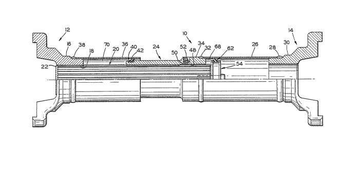
Referring to the drawings, and more particularly to Fig. 1,
a driveshaft embodying the invention is indicated at 10 and


3~ 5

2 ~ ~ 6 ~ ~ ) .3

connects a first universal jolnt yoke 12 and a second universal
joint yoke 14. The yokes can be of various designs to accom-
modate particular unlversal joirlt crosses of particular styles.
The universal joint yoke 12 includes a hub 16 having an
05 internally-splined central passage 18. ~ male splined shafk
20 extends rearwardly of the first yoke 12 and rotates therewith.
In this instance, the s~lined shaft 20 is engaged with internal
splines of the passage 18 and is welded at 22 to the hub 18.
The splined shaft 20 is of predetermined length which can vary
considerably from application to application. Other means can
be employed to affix the shaft to the yoke and in some instances
they can be structurally integral.


A female splined shaft 24 extends rearwardly of the second
universal joint yoke 14 and rotates therewith. In this instance,
the female splined shaft 24 is affixed to the yoke 14 -through
a propeller shaft or tube 26 which is welded at 28 to a solid
yoke hub 30 and welded at 32 to an end portion 34 of the female
splined shaft 24. The length of the propeller shaft also can
vary considerably from application to application


The seal in accordance with the invention includes a
sealing sleeve 35 extending rearwardly of the first unl~ersal
joint yoke 12 and being rotatable therewith. In this instance,
the sleeve 36 is affixed to the hub 16 of the yoke by a weld
38 at tlle end of the sleeve. The sealing slee-ve 36 has an
internal diameter exceeding the outer diameter of the female

splined shaft 24 and has a sufficient length such that the


3~ -6-

2 ~

splined shaft 20 will. not be exposed and thc outer end portion
of the :female splined shaft ~ill always be within the sealing
sleeve 36 for any operating position of the driveshaft lO.


~5 The seal in accordance with the invention includes a
sealing ring ~0 carried in an external annular groove 42 at
an outer end of the female splined shaft 24 opposite the second
universal joint yoke 14. 'Ihe sealillg ring 40 i.ncludes an annular
base band 44 ~Fig. 2) and a lip 46 extending~ou-twardly therefrom
10 and slanting toward the second universal joint yo~ce 14. With
tllis arrangement of the lip 46, any excess grease can pass the
lip 46 toward the open end of the sleeve 36. Further~ wllen
tlle driveshaft lO is moving toward -the expanded condition,
the lip 46 is effective to wipe any contaminants off -the inner
15 surface of the sleeve 36, which is relatively clean and never
exposed directly to the elements. The sealing ring 40 is
somewhat resilient so that the base band 44 can be stretched
over the end o:E the shaft 24 and resiliently held under tension
in the bottom of the external groove 42. The resiliency also
20 enables the lip 46 to mai.ntain uniform contac-t with tlle
inner surface of the sleeve 36. By way of example, the sealing
ring 40 can be made of carboxylated nitril.e materi.al with a
hardness in the order of eighty-five durometers (Shore ~).


With the sealing ring 40 externally mounted on the shaft
24, it only contacts the inner surface of the sleeve 36 and is
never in contact with a surface of a shaft which is sometimes

exposed to the elernents and on which contaminants and water can
be deposited.
3~ -7-


The female splined shaft 24 has an inner annular recess 48
at the end 34 beyond the internal splines. A transverse bore 50
communicates with a portion o tile annular recess 48 and can
receive a supply of grease from a grease gun or the like and
05 force it in both directions.


A cylindrical body or piston 54 with an external groove 56
~ig. 3) is affixed to the end of the male splined shaft 20
which is closer to the yoke 14 by a machine screw 58 received in
a threaded bore 60 centrally positioned in the shaft. The
sealing ring 62 also has a base band 64 and a lip 66, with the
lip preferably facing toward the yoke 12 to better retain grease.
The sealing ring can be stretched over the piston with the base
band 64 held in tension in the bottom of the groove S6. In a
preferred form, the sleeve 36 and the tube 26 are of the same
diameter to reduce inventory parts. This also enables the
sealing ring 62 -to be of the same size and shape as the sealing
ring 40 so that the one ring serves both purposes. The sealing
ring 62 can also be made of the same material as the sealing
ring 40. The lip 66 of the sealing ring 62 always engages the
inner surface of the tube Z6 and is never exposed to ou-tside
elements, including contaminants and water.


An annular grease chamber 68 is -formed beyond the female
splined shaft 24 by the tube 26, the female shaft end 34, the
piston 54 and the sealing ring 62, and the male splined shaft 2C.
Likewise, an annular grease chamber 70 is formed at the other end
of the female splined shaft 24 between the sleeve 36, the yoke


-8-

~3~

hub lfi, the sealing ring 40, and the male sp]ined shaf-t 20.
The volumes of the chambers G8 and 70 vary as khe yokes 12 and
14 move toward and away Erom one another. I-lowever, the volume
of one oE the chambers 68 and 70 increases as the other decreases
05 so that the total volume remains substantially constant.
Initially, both of the chambers 68 and 70 are filled with
grease supplied through the E;tting 52, the bore 50, the recess
48, and between the teeth or splines and the groove of the
shafts 20 and 24. The grease is forced back and forth between
the chambers 68 and 70 as the effective length of the driveshaft
increases and decreases. This grease is supplied between the
engaged splines and grooves so -that it is available exactly
where it is needed most. The combined volumes of the chambers
68 and 70 can provide several times the capacity of driveshaft
seals heretofore commonly used.


The splines and grooves of the shafts are designed to enable
grease to pass between tips of the splines and the bottoms of
the grooves, as shown in ~ig. 4. Ilere, tips of splines 72 of the
male splined shaft 20 stop short of the bottoms of grooves 74 of
the female splined shaf-t 24. Likewise, -tips oE splines 76 of the
female splined shaft 24 stop short of the bottoms of grooves 78
of the male splined shaft 20. ~t the same time, however, the
sides,of the teeth and grooves are substantially fully engaged
to still provide proper contact area therebe-tween.


The basic design of the driveshaft sealing arrangement in

accordance with the invention is compatible with subs-tantially an~
manufacturers' series of universal joints and driveshafts
0 presently in use.
g


~72~

Various modifications of the above-described embodiment
of the inverltion will be apparent to tllose skilled in the art,
and i.t is to be understood t}lat sllch modifications can be made
witllout departing from the scope o~ the invention, if t}ley are
05 Wit}lill the spirit and the tenor o:E the accompanying claims.


3 ~ - I O -

Representative Drawing
A single figure which represents the drawing illustrating the invention.
Administrative Status

For a clearer understanding of the status of the application/patent presented on this page, the site Disclaimer , as well as the definitions for Patent , Administrative Status , Maintenance Fee  and Payment History  should be consulted.

Administrative Status

Title Date
Forecasted Issue Date Unavailable
(22) Filed 1993-01-14
(41) Open to Public Inspection 1993-10-07
Dead Application 2001-01-15

Abandonment History

Abandonment Date Reason Reinstatement Date
2000-01-14 FAILURE TO REQUEST EXAMINATION
2000-01-14 FAILURE TO PAY APPLICATION MAINTENANCE FEE

Payment History

Fee Type Anniversary Year Due Date Amount Paid Paid Date
Application Fee $0.00 1993-01-14
Maintenance Fee - Application - New Act 2 1995-01-16 $50.00 1994-12-22
Maintenance Fee - Application - New Act 3 1996-01-15 $50.00 1995-12-21
Maintenance Fee - Application - New Act 4 1997-01-14 $50.00 1996-12-20
Maintenance Fee - Application - New Act 5 1998-01-20 $75.00 1998-01-12
Maintenance Fee - Application - New Act 6 1999-01-14 $75.00 1999-01-07
Owners on Record

Note: Records showing the ownership history in alphabetical order.

Current Owners on Record
BURTON, ROBERT A.
Past Owners on Record
None
Past Owners that do not appear in the "Owners on Record" listing will appear in other documentation within the application.
Documents

To view selected files, please enter reCAPTCHA code :


To view images, click a link in the Document Description column. To download the documents, select one or more checkboxes in the first column and then click the "Download Selected in PDF format (Zip Archive)" or the "Download Selected as Single PDF" button.

List of published and non-published patent-specific documents on the CPD .

If you have any difficulty accessing content, you can call the Client Service Centre at 1-866-997-1936 or send them an e-mail at CIPO Client Service Centre.


Document
Description 
Date
(yyyy-mm-dd) 
Number of pages   Size of Image (KB) 
Description 1993-10-07 9 333
Cover Page 1993-10-07 1 18
Abstract 1993-10-07 1 34
Claims 1993-10-07 7 242
Drawings 1993-10-07 2 58
Representative Drawing 1999-06-21 1 23
Fees 1998-01-12 1 30
Fees 1999-01-07 1 30
Fees 1996-12-20 1 67
Fees 1995-12-21 1 56
Fees 1994-12-22 1 61