Note: Descriptions are shown in the official language in which they were submitted.
2087362
NEEDLE SHEATH WITH PROTECTIVE GUARD
FIELD OF THE_INVENTION
The present invention relates to hypodermic needles
for syringes and to sheaths therefor.
BACKGROUND OF THE INVENT _
In recent years the risk of infection with serious
diseases through the use of hypodermic needles has become a
major concern for those who handle such appliances. Medical
and dental practitioners, for example, are at risk of
infection through an accidental prick with a used needle.
To address this problem, a number of devices have
been proposed for holding the sheaths of disposable needles,
while protecting the hand of the user as a used needle is
reinserted into the sheath for disposal. Some of these
devices are bulky and awkward to use and have not found
favour for that reason. All such devices are additional
appliances that are intended to be reused. Consequently,
when using such a protective device, it is necessary that it
be sterilized, normally by autoclaving, after each use.
Consequently, because of the nuisance factor involved in the
use of these devices, they are not always employed.
It is an object of the present ir.vention to provide
the desired protection integrally with a needle sheath.
2~73~i2
SUMMARY OF THE INVENTION
According to one aspect of the present invention
there is provided a sheath for a hypodeI~nic needle assembly
comprising a tube having an open needle~ receiving end, a
gripping portion spaced from the needle receiving end and a
flange secured to the sheath between the open needle
receiving end and the gripping portion.
According to another aspect of the present invention
there is provided a hypodermic needle and sheath assembly
comprising:
a tube having an open end;
a cap engaging over the open end of the tube;
a needle assembly including a needle projecting into
the tube and a body held in the open end of the tube; and
a flange surrounding the tube.
The protective flange is therefore unitary with the
disposable sheath and will provide protection every time a
needle is used without the requirement for an additional
device. The entire sheath and needle assembly is disposable,
so that the protective device need not be sterilized for
reuse.
~ BRIEF DESCRIPTION OF THE DRAWINGS
- In the accompanying drawings which illustrate an
exemplary embodiment of the present invention:
Figure 1 is an isometric view of a needle and sheath
` ~ ` ` ' `: ~: ` ` .
`
','` ` ' : ' ' ' ` '
2087362
assembly according to the present invention;
Figure 2 is a side elevation of the assembly of
Figure l;
Figure 3 is a side elevation of the assembly with the
cap removed;
Figure 4 is a longitudinal cross section of the
assembly; and
Figure 5 is an end view of the sheath from the needle
receiving end thereof.
DETAILED DESCRIPTION
~ .
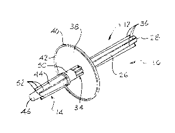
Referring to the accompanying drawings there is
illustrated a needle and sheath assembly 10 that includes a
sheath 12 and a cap 14. These house a needle assembly 16
that is most clearly ill~strated in Figure 4.
The needle assembly includes a needle body 18 in the
form of a cap with a bore 20 at the outer end and threads 22
on the inside of the bore. The threads 22 are used to engage
the end of a conventional syringe. A needle 24 extends
through the body in the conventional way.
The sheath 12 of the needle and sheath assembly
includes a tube 26 with a closed end 28 and an open, needle
reGeiving end 30. At the needle receiving end the tube is
formed into a sleeve 32 that engages the needle body 18 and
holds it in place with the end of the needle 24 projecting
into the tube. Adjacent the sleeve 32 is a ring of ribs 34
20~73fi2
that surrounds the tube to provide stiffness at this point.
A further series of ribs 36 extend the 'ength of the tube,
between the ribs 34 and the closed end 2~. These serve both
to stiffen this end of the tube and also allow the firm
gripping of the tube so that it can be twisted off the needle
body 18 when the body is screwed onto a syringe.
Surrounding the sheath between the gripping portion
carrying the ribs 36 and the ribs 34 is a circular flange 38
concentric with the tube. The flange has a peripheral edge
40 carrying a lip 42 projecting towards the cap 14, that is
away from the gripping portion of the tube 26. The lip
serves to inhibit a needle engaging the flange from sliding
off the flange and accidently pricking the user.
The cap 14 includes a tube 44 with a closed end 46
and an open end 48. Adjacent the open end, the tube forms a
~leeve 50 for engagement over the sleeve 32 of the sheath 12.
With the cap installed, the needle assembly 16 is completely
enclosed by the sheath and the cap. A series of ribs 52
extend along the tube 44 and serves for stiffening and
gripping purposes.
The needle and sheath assembly are used in the same
way as the conventional disposable needle and sheath
assembly. That is, the cap 14 is removed from the assembly
so that the needle may be screwed onto the end of a syringe.
Once that has been accomplished, the sheath may be removed
and the needle used as desired. On completion of its use,
2V87.':~fi2
the needle 24 is reinserted into the tube 26 and the needle
body 18 is engaged in the sleeve 32. During this process,
the sheath is gripped from the gripping end behind the flange
38, which thus protects the hand of the user. Once the
needle body 18 has been inserted in the sleeve 32, the needle
may be unscrewed from a syringe and the cap reinstalled to
completely enclose the used needle for disposal.
While one embodiment of the present invention has
been described in the foregoing, it is to be understood that
other embodiments are possible within the scope of the
invention. It is, for example, possible to relocate the
flange 38 on the tube 26 provided its location is sufficient
to provide the necessary guarding function and provided that
it does not interfere with any other necessary function of
the needle and sheath assembly. It is therefore to be
understood that the invention is to be considered limited
solely by the scope of the appended claims.