Sélection de la langue

Search

Sommaire du brevet 2087362 

Énoncé de désistement de responsabilité concernant l'information provenant de tiers

Une partie des informations de ce site Web a été fournie par des sources externes. Le gouvernement du Canada n'assume aucune responsabilité concernant la précision, l'actualité ou la fiabilité des informations fournies par les sources externes. Les utilisateurs qui désirent employer cette information devraient consulter directement la source des informations. Le contenu fourni par les sources externes n'est pas assujetti aux exigences sur les langues officielles, la protection des renseignements personnels et l'accessibilité.

Disponibilité de l'Abrégé et des Revendications

L'apparition de différences dans le texte et l'image des Revendications et de l'Abrégé dépend du moment auquel le document est publié. Les textes des Revendications et de l'Abrégé sont affichés :

  • lorsque la demande peut être examinée par le public;
  • lorsque le brevet est émis (délivrance).
(12) Demande de brevet: (11) CA 2087362
(54) Titre français: FOURREAU POUR AIGUILLE AVEC DISPOSIFIF DE PROTECTION
(54) Titre anglais: NEEDLE SHEATH WITH PROTECTIVE GUARD
Statut: Réputée abandonnée et au-delà du délai pour le rétablissement - en attente de la réponse à l’avis de communication rejetée
Données bibliographiques
Abrégés

Abrégé anglais


ABSTRACT
A sheath for a hypodermic needle assembly
comprising a tube having an open needle receiving end, a
gripping portion spaced from the needle receiving end and a
flange secured to the sheath between the open needle
receiving end and the gripping portion.

Revendications

Note : Les revendications sont présentées dans la langue officielle dans laquelle elles ont été soumises.


-6-
CLAIMS
1. A sheath for a hypodermic needle assembly
comprising a tube having an open needle receiving end, a
gripping portion spaced from the needle receiving end and a
flange secured to the sheath between the open needle
receiving end and the gripping portion.
2. A sheath according to claim 1 wherein the flange
is space from the needle receiving end.
3. A sheath according to claim 2 wherein the flange
comprises a peripheral lip projecting away from the gripping
portion.
4. A sheath according to claim 1 wherein the needle
receiving end comprises means for engaging a body of the
hypodermic needle assembly for retaining the needle assembly
in the sheath.
5. A sheath according to claim 1 wherein the sheath
further comprises a cap for engagement with the open needle
receiving end of the tube for closing the needle receiving
end and cooperating with the tube to enclose the needle
assembly.
6. A hypodermic needle and sheath assembly
comprising:
a tube having an open end;
a cap engaging over the open end of the tube;
a needle assembly including a needle projecting into
the tube and a body held in the open end of the tube; and

-7-
a flange surrounding the tube.
7. An assembly according to claim 6 wherein the
flange is adjacent the open end of the tube.
8. An assembly according to claim 6 wherein the
flange comprises a peripheral lip projecting from the flange
towards the cap.

Description

Note : Les descriptions sont présentées dans la langue officielle dans laquelle elles ont été soumises.

2087362
NEEDLE SHEATH WITH PROTECTIVE GUARD
FIELD OF THE_INVENTION
The present invention relates to hypodermic needles
for syringes and to sheaths therefor.
BACKGROUND OF THE INVENT _
In recent years the risk of infection with serious
diseases through the use of hypodermic needles has become a
major concern for those who handle such appliances. Medical
and dental practitioners, for example, are at risk of
infection through an accidental prick with a used needle.
To address this problem, a number of devices have
been proposed for holding the sheaths of disposable needles,
while protecting the hand of the user as a used needle is
reinserted into the sheath for disposal. Some of these
devices are bulky and awkward to use and have not found
favour for that reason. All such devices are additional
appliances that are intended to be reused. Consequently,
when using such a protective device, it is necessary that it
be sterilized, normally by autoclaving, after each use.
Consequently, because of the nuisance factor involved in the
use of these devices, they are not always employed.
It is an object of the present ir.vention to provide
the desired protection integrally with a needle sheath.

2~73~i2
SUMMARY OF THE INVENTION
According to one aspect of the present invention
there is provided a sheath for a hypodeI~nic needle assembly
comprising a tube having an open needle~ receiving end, a
gripping portion spaced from the needle receiving end and a
flange secured to the sheath between the open needle
receiving end and the gripping portion.
According to another aspect of the present invention
there is provided a hypodermic needle and sheath assembly
comprising:
a tube having an open end;
a cap engaging over the open end of the tube;
a needle assembly including a needle projecting into
the tube and a body held in the open end of the tube; and
a flange surrounding the tube.
The protective flange is therefore unitary with the
disposable sheath and will provide protection every time a
needle is used without the requirement for an additional
device. The entire sheath and needle assembly is disposable,
so that the protective device need not be sterilized for
reuse.
~ BRIEF DESCRIPTION OF THE DRAWINGS
- In the accompanying drawings which illustrate an
exemplary embodiment of the present invention:
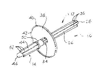
Figure 1 is an isometric view of a needle and sheath
` ~ ` ` ' `: ~: ` ` .
`
','` ` ' : ' ' ' ` '

2087362
assembly according to the present invention;
Figure 2 is a side elevation of the assembly of
Figure l;
Figure 3 is a side elevation of the assembly with the
cap removed;
Figure 4 is a longitudinal cross section of the
assembly; and
Figure 5 is an end view of the sheath from the needle
receiving end thereof.
DETAILED DESCRIPTION
~ .
Referring to the accompanying drawings there is
illustrated a needle and sheath assembly 10 that includes a
sheath 12 and a cap 14. These house a needle assembly 16
that is most clearly ill~strated in Figure 4.
The needle assembly includes a needle body 18 in the
form of a cap with a bore 20 at the outer end and threads 22
on the inside of the bore. The threads 22 are used to engage
the end of a conventional syringe. A needle 24 extends
through the body in the conventional way.
The sheath 12 of the needle and sheath assembly
includes a tube 26 with a closed end 28 and an open, needle
reGeiving end 30. At the needle receiving end the tube is
formed into a sleeve 32 that engages the needle body 18 and
holds it in place with the end of the needle 24 projecting
into the tube. Adjacent the sleeve 32 is a ring of ribs 34

20~73fi2
that surrounds the tube to provide stiffness at this point.
A further series of ribs 36 extend the 'ength of the tube,
between the ribs 34 and the closed end 2~. These serve both
to stiffen this end of the tube and also allow the firm
gripping of the tube so that it can be twisted off the needle
body 18 when the body is screwed onto a syringe.
Surrounding the sheath between the gripping portion
carrying the ribs 36 and the ribs 34 is a circular flange 38
concentric with the tube. The flange has a peripheral edge
40 carrying a lip 42 projecting towards the cap 14, that is
away from the gripping portion of the tube 26. The lip
serves to inhibit a needle engaging the flange from sliding
off the flange and accidently pricking the user.
The cap 14 includes a tube 44 with a closed end 46
and an open end 48. Adjacent the open end, the tube forms a
~leeve 50 for engagement over the sleeve 32 of the sheath 12.
With the cap installed, the needle assembly 16 is completely
enclosed by the sheath and the cap. A series of ribs 52
extend along the tube 44 and serves for stiffening and
gripping purposes.
The needle and sheath assembly are used in the same
way as the conventional disposable needle and sheath
assembly. That is, the cap 14 is removed from the assembly
so that the needle may be screwed onto the end of a syringe.
Once that has been accomplished, the sheath may be removed
and the needle used as desired. On completion of its use,

2V87.':~fi2
the needle 24 is reinserted into the tube 26 and the needle
body 18 is engaged in the sleeve 32. During this process,
the sheath is gripped from the gripping end behind the flange
38, which thus protects the hand of the user. Once the
needle body 18 has been inserted in the sleeve 32, the needle
may be unscrewed from a syringe and the cap reinstalled to
completely enclose the used needle for disposal.
While one embodiment of the present invention has
been described in the foregoing, it is to be understood that
other embodiments are possible within the scope of the
invention. It is, for example, possible to relocate the
flange 38 on the tube 26 provided its location is sufficient
to provide the necessary guarding function and provided that
it does not interfere with any other necessary function of
the needle and sheath assembly. It is therefore to be
understood that the invention is to be considered limited
solely by the scope of the appended claims.

Dessin représentatif
Une figure unique qui représente un dessin illustrant l'invention.
États administratifs

2024-08-01 : Dans le cadre de la transition vers les Brevets de nouvelle génération (BNG), la base de données sur les brevets canadiens (BDBC) contient désormais un Historique d'événement plus détaillé, qui reproduit le Journal des événements de notre nouvelle solution interne.

Veuillez noter que les événements débutant par « Inactive : » se réfèrent à des événements qui ne sont plus utilisés dans notre nouvelle solution interne.

Pour une meilleure compréhension de l'état de la demande ou brevet qui figure sur cette page, la rubrique Mise en garde , et les descriptions de Brevet , Historique d'événement , Taxes périodiques et Historique des paiements devraient être consultées.

Historique d'événement

Description Date
Inactive : CIB de MCD 2006-03-11
Inactive : Inventeur supprimé 2002-06-12
Le délai pour l'annulation est expiré 1995-07-15
Demande non rétablie avant l'échéance 1995-07-15
Réputée abandonnée - omission de répondre à un avis sur les taxes pour le maintien en état 1995-01-16
Inactive : Demande ad hoc documentée 1995-01-16
Demande publiée (accessible au public) 1994-07-16

Historique d'abandonnement

Date d'abandonnement Raison Date de rétablissement
1995-01-16
Titulaires au dossier

Les titulaires actuels et antérieures au dossier sont affichés en ordre alphabétique.

Titulaires actuels au dossier
DEREK A. GAUDES
Titulaires antérieures au dossier
S.O.
Les propriétaires antérieurs qui ne figurent pas dans la liste des « Propriétaires au dossier » apparaîtront dans d'autres documents au dossier.
Documents

Pour visionner les fichiers sélectionnés, entrer le code reCAPTCHA :


Pour visualiser une image, cliquer sur un lien dans la colonne description du document. Pour télécharger l'image (les images), cliquer l'une ou plusieurs cases à cocher dans la première colonne et ensuite cliquer sur le bouton "Télécharger sélection en format PDF (archive Zip)" ou le bouton "Télécharger sélection (en un fichier PDF fusionné)".

Liste des documents de brevet publiés et non publiés sur la BDBC .

Si vous avez des difficultés à accéder au contenu, veuillez communiquer avec le Centre de services à la clientèle au 1-866-997-1936, ou envoyer un courriel au Centre de service à la clientèle de l'OPIC.


Description du
Document 
Date
(aaaa-mm-jj) 
Nombre de pages   Taille de l'image (Ko) 
Page couverture 1994-07-16 1 30
Dessins 1994-07-16 2 44
Revendications 1994-07-16 2 83
Abrégé 1994-07-16 1 45
Description 1994-07-16 5 210
Dessin représentatif 1998-08-12 1 8
Courtoisie - Lettre du bureau 1993-03-08 1 51
Correspondance reliée au PCT 1993-07-26 1 23
Courtoisie - Lettre du bureau 1993-07-14 1 17