Language selection

Search

Patent 2087440 Summary

Third-party information liability

Some of the information on this Web page has been provided by external sources. The Government of Canada is not responsible for the accuracy, reliability or currency of the information supplied by external sources. Users wishing to rely upon this information should consult directly with the source of the information. Content provided by external sources is not subject to official languages, privacy and accessibility requirements.

Claims and Abstract availability

Any discrepancies in the text and image of the Claims and Abstract are due to differing posting times. Text of the Claims and Abstract are posted:

  • At the time the application is open to public inspection;
  • At the time of issue of the patent (grant).
(12) Patent: (11) CA 2087440
(54) English Title: INTERLOCKING PALLET
(54) French Title: PALETTE INTERVERROUILLABLE
Status: Expired and beyond the Period of Reversal
Bibliographic Data
(51) International Patent Classification (IPC):
  • B65D 19/06 (2006.01)
  • B65D 19/00 (2006.01)
  • B65D 19/44 (2006.01)
(72) Inventors :
  • REYNOLDS, WILLIAM BOYD (United States of America)
(73) Owners :
  • E. I. DU PONT DE NEMOURS AND COMPANY
(71) Applicants :
  • E. I. DU PONT DE NEMOURS AND COMPANY (United States of America)
(74) Agent: BENNETT JONES LLP
(74) Associate agent:
(45) Issued: 2001-09-11
(86) PCT Filing Date: 1991-07-17
(87) Open to Public Inspection: 1992-02-06
Examination requested: 1998-07-13
Availability of licence: N/A
Dedicated to the Public: N/A
(25) Language of filing: English

Patent Cooperation Treaty (PCT): Yes
(86) PCT Filing Number: PCT/US1991/004887
(87) International Publication Number: US1991004887
(85) National Entry: 1993-01-15

(30) Application Priority Data:
Application No. Country/Territory Date
07/554,474 (United States of America) 1990-07-19

Abstracts

English Abstract


A pallet (10) having at least two sections (12 14, 16, 18) has interlocking
means (36, 38) for joining the sections together,
the interlocking means comprising knuckles (36, 38) on sections which mate to
receive a releasable locking member (74).


Claims

Note: Claims are shown in the official language in which they were submitted.

-6-
CLAIMS
1. A pallet comprised of at least two
sections having releasable interlocking means for joining
said sections together, each section having a top load
supporting deck with an underlying supporting member, a
plurality of knuckles integral with and spaced along the
periphery of at least one side of said top load
supporting deck and a plurality of knuckles integral with
and spaced along the underlying supporting member on an
adjoining side of said deck, the knuckles on a first
section of said pallet being spaced apart to permit
mating with corresponding knuckles on a second section of
said pallet, said knuckles being adapted to receive a
releasable locking member when brought into mating
relationship, said sections being joined together to
provide a rigid integrated platform when said locking
member is inserted through the knuckles on said first and
second sections of said pallet.
2. The pallet of claim 1 wherein each
section of said pallet has a node centrally located
and projecting from the surface of said deck for
receiving a hollow core of a roll when said roll is
placed in a standing position on said deck.
3. The pallet of claim 1 wherein each
section has foot members contiguous with said
underlying members, said foot members being positioned
at each corner of said section.
4. The pallet of claim 1 wherein said
knuckles have eyes adapted to receive an elongated rod
for securing said sections in interlocking
relationship.

-7-
5. A pallet comprised of at least two
sections having releasable interlocking means for
joining said sections together, each section having a
top load supporting deck with foot members positioned
at each corner of said section, each section having a
first set of knuckles integral with and spaced along
the periphery of the surface of at least one side of
said deck and a second set of knuckles integral with a
spaced along a member underlying said first set of
knuckles, said first and second sets of knuckles being
spaced apart to permit mating with knuckles on a
second section of said pallet, said knuckles being
adapted to receive a releasable locking member when
brought into mating relationship said sections being
joined together to provide a rigid integrated platform
when said locking member is inserted through said
knuckles on said first and second sections on said
pallet.
6. The pallet of claim 5 wherein each
section of said pallet has at least one node
projecting from the surface of said deck for receiving
a hollow core of a roll when said roll is placed in an
upright position on said deck.
7. The pallet of claim 5 wherein said foot
members are contiguous with members underlying said
supporting deck.
8. The pallet of claim 5 wherein said
knuckles have eyes adapted to receive an elongated rod
for securing said sections in interlocking
relationship.

Description

Note: Descriptions are shown in the official language in which they were submitted.


WO 92/01607 ~ ~ ~ ~ ~ ~ ~ PCT/US91/04887
1
TITLE
INTERLOCKING PALLET
BACKGROUND OF THE INVENTION
This invention relates to a new interlocking
pallet comprised of at least two sections which can be
joined together.
Interlocking pallets which are formed by a
plurality of sections are known. These pallets are
useful for supporting loads to be moved by lift
trucks, particularly when only a portion of a load is
to be transported from place to place. Such a pallet
is disclosed in U.S. Pat. No. 3,650,224. While the
various sections of the pallet can be joined in a
releasable interlocking relationship, no positive
locking means is provided, and in lifting and moving
the pallet, the sections may come apart.
SUMMARY OF THE INVENTION
In accordance with the present invention
there is provided a pallet consisting of at least two
sections having releasable interlocking means for
positively joining the sections together. The locking
means effectively prevents separation of the sections
during both lateral and vertical movement of the
pallet.
Each section of the pallet has a top load
supporting deck with foot members positioned at each
corner of the section. The locking means comprises
knuckles on each section which can be brought into
mating relationship. The knuckles of a first section
are spaced apart along the periphery of at least one
side of the deck and along an underlying member on an
adjoining side of the deck. When similarly configured

WO 92/01607 ~ ~ ~ ~ ~ ~ PCT/US91/0488'
2
sections are in the mated position, the two sections
can be locked together by inserting a locking member
through openings in the mated knuckles.
In another embodiment of the pallet of this
invention, knuckles on a first section of the pallet
are spaced apart along the periphery of the surface of
at least one side of the deck and along a member
underlying the side of the deck. Knuckles on a second
section of the pallet are similarly spaced apart as
just described to permit mating with knuckles on the
first section of the pallet. When the knuckles of the
two sections are in the mated position, the sections
can be locked together by inserting a locking member
through openings in the mated knuckles.
BRIEF DESCRIPTION OF THE DRAWINGS
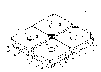
FIG. 1 is a perspective view of a pallet of
the present invention illustrated by four interlocked
sections;
FIG. 2 is a view of one section of the
pallet of FIG. 1;
FIG. 3 is view of the pallet shown in FIG. 1
in a partially broken down state:
FIG. 4 is a view of another embodiment of
the present invention illustrated by two interlocked
sections: and
FIG. 5 is a view of one section of the
pallet of FIG. 4.
DETAILED DESCRIPTION OF THE PREFERRED EMBODIMENT
Referring to Figure 1, pallet 10 is
comprised of four sections 12, 14, 16 and 18. Each of
the four sections is substantially identical having a
top load supporting deck 20, 22, 24 and 26 and foot

2087440
WO 92/01607 PCT/US91/04887
3
members 21, 23, 25, 28, 30, 32 and 34 at the corners
of each section.
Section 12 is shown in more detail in Figure
2. Knuckles 36, 36' and 36" are spaced apart along
the periphery of the surface of deck 20. Similar
knuckles 38, 38' and 38" are spaced apart along
stringer 40. The knuckles have eyes 42, 42', 42", 44,
44' and 44" for receiving locking members. Sections
14, 16 and 18 include similarly spaced knuckles and
eyes.
As shown in Figure 1, the sections have
openings 46, 48, 50 and 52 which are wide enough to
permit entry of the forks of a fork-lift or pallet
truck. Stingers 54, 56, 58 and 59 have beveled outer
and interior surfaces, preferably beveled at a 45
degree angle, to permit easy access and withdrawal of
the wheels of a pallet truck.
The embodiments shown in the Figures are
configured to transport large rolls of film. As shown
in Figure 1, nodes 60, 61, 62 and 64 protrude from the
surface of the sections. An open end of the core of a
roll in an upright position is placed over the node to
assist in retaining the roll on the pallet. The node
as well as the surface of the section should be
suitably reinforced for supporting heavy loads. Other
cc~figurations could be used to accommodate
di~ferently shaped loads.
As best shown in Figure 2, the surface 20 of
section 12 includes wells 66, 68 and 70 for receiving
corner posts. A triangular shaped post 72, a portion
of which is shown, or other configuration may be used.
The posts can support a cover plate, not shown, which
would include nodes for receiving the open end of the
core of a roll standing on the pallet. A cover plate
is necessary to protect the rolls on the pallet during

WO 92/01607
PCT/US91 /0488'
4
shipping and stacking. A stretch-wrap package can be
provided for encasing the pallet, rolls and the cover
plate using a suitable polymeric film.
Referring now to Figure 3, pallet 12 is
shown in a partially broken down state. Locking rod
74 is shown partially inserted through the knuckles of
adjoining sections 16 and 18. A second locking rod 76
is also shown partially inserted through knuckles on
sections 14 and 18. When rod 74 is fully inserted,
bent end 78 fits into groove 80 which is formed
between sections 16 and 18. A similar groove
accommodates the end of rod 76.
In another embodiment of the pallet of this
invention shown in Figure 4, sections 82 and 84 have
knuckles 86, 86', 86", 88, 88' and 88" spaced along
the periphery of decks 90 and 92. Rod 94 is shown in
the locking position securing the sections together.
Section 82 is shown in more detail in Figure
5. A second set of knuckles 98, 98' and 98" is shown
on underlying stringer 100. When two sections are
mated, locking rods can be inserted in both the upper
and lower sets of knuckles. The surface of the deck
102 of section 82 is configured with nodes 104, 106,
108, 110 and 112 to receive the hollow end of cores of
rolls of film.
The pallets of this invention may be
constructed from a variety of materials. They may be
molded from polymeric materials such as ABS resins,
high density polyethylene and polyesters. Recylcable
material are particularly suited for this purpose. In
molding the pallets the deck portions and the lower
portion which includes the stringers and foot members
can each be molded separately and joined together by
suitable fastening means. Preferably, the foot
members and stringers are molded simultaneously as

WO 92/01607 ~ ~ 3 ~ ~ ~ ~ PCT/US91 /04887
contiguous members. However, the sections of the
pallet may be molded as integral units. Various known
molding techniques can be used.
While particular embodiments of this
5 invention have been shown and described, it will be
apparent to those skilled in the art that various
changes and modifications may be made therein without
departing from the scope of the invention.
15
25
35

Representative Drawing
A single figure which represents the drawing illustrating the invention.
Administrative Status

2024-08-01:As part of the Next Generation Patents (NGP) transition, the Canadian Patents Database (CPD) now contains a more detailed Event History, which replicates the Event Log of our new back-office solution.

Please note that "Inactive:" events refers to events no longer in use in our new back-office solution.

For a clearer understanding of the status of the application/patent presented on this page, the site Disclaimer , as well as the definitions for Patent , Event History , Maintenance Fee  and Payment History  should be consulted.

Event History

Description Date
Time Limit for Reversal Expired 2010-07-19
Letter Sent 2009-07-17
Inactive: IPC from MCD 2006-03-11
Grant by Issuance 2001-09-11
Inactive: Cover page published 2001-09-10
Letter Sent 2001-05-17
Amendment After Allowance Requirements Determined Compliant 2001-05-17
Inactive: Final fee received 2001-04-18
Amendment After Allowance (AAA) Received 2001-04-18
Inactive: Amendment after Allowance Fee Processed 2001-04-18
Pre-grant 2001-04-18
Letter Sent 2001-01-05
Notice of Allowance is Issued 2001-01-05
Inactive: Approved for allowance (AFA) 2000-12-11
Inactive: Office letter 1999-02-26
Inactive: Application prosecuted on TS as of Log entry date 1998-08-07
Inactive: RFE acknowledged - Prior art enquiry 1998-08-07
Inactive: Status info is complete as of Log entry date 1998-08-07
All Requirements for Examination Determined Compliant 1998-07-13
Request for Examination Requirements Determined Compliant 1998-07-13
Application Published (Open to Public Inspection) 1992-02-06

Abandonment History

There is no abandonment history.

Maintenance Fee

The last payment was received on 2001-06-26

Note : If the full payment has not been received on or before the date indicated, a further fee may be required which may be one of the following

  • the reinstatement fee;
  • the late payment fee; or
  • additional fee to reverse deemed expiry.

Patent fees are adjusted on the 1st of January every year. The amounts above are the current amounts if received by December 31 of the current year.
Please refer to the CIPO Patent Fees web page to see all current fee amounts.

Fee History

Fee Type Anniversary Year Due Date Paid Date
MF (application, 6th anniv.) - standard 06 1997-07-17 1997-06-19
MF (application, 7th anniv.) - standard 07 1998-07-17 1998-06-17
Request for examination - standard 1998-07-13
MF (application, 8th anniv.) - standard 08 1999-07-19 1999-06-15
MF (application, 9th anniv.) - standard 09 2000-07-17 2000-06-23
2001-04-18
Final fee - standard 2001-04-18
MF (application, 10th anniv.) - standard 10 2001-07-17 2001-06-26
MF (patent, 11th anniv.) - standard 2002-07-17 2002-06-17
MF (patent, 12th anniv.) - standard 2003-07-17 2003-06-19
MF (patent, 13th anniv.) - standard 2004-07-19 2004-06-16
MF (patent, 14th anniv.) - standard 2005-07-18 2005-06-07
MF (patent, 15th anniv.) - standard 2006-07-17 2006-06-07
MF (patent, 16th anniv.) - standard 2007-07-17 2007-06-07
MF (patent, 17th anniv.) - standard 2008-07-17 2008-06-10
Owners on Record

Note: Records showing the ownership history in alphabetical order.

Current Owners on Record
E. I. DU PONT DE NEMOURS AND COMPANY
Past Owners on Record
WILLIAM BOYD REYNOLDS
Past Owners that do not appear in the "Owners on Record" listing will appear in other documentation within the application.
Documents

To view selected files, please enter reCAPTCHA code :


To view images, click a link in the Document Description column. To download the documents, select one or more checkboxes in the first column and then click the "Download Selected in PDF format (Zip Archive)" or the "Download Selected as Single PDF" button.

List of published and non-published patent-specific documents on the CPD .

If you have any difficulty accessing content, you can call the Client Service Centre at 1-866-997-1936 or send them an e-mail at CIPO Client Service Centre.


Document
Description 
Date
(yyyy-mm-dd) 
Number of pages   Size of Image (KB) 
Claims 1994-05-13 2 101
Claims 1998-09-07 2 80
Abstract 1995-08-16 1 49
Description 1994-05-13 5 178
Drawings 1994-05-13 3 73
Claims 2001-04-17 2 77
Representative drawing 1998-07-29 1 11
Representative drawing 2001-08-26 1 13
Reminder - Request for Examination 1998-03-17 1 118
Acknowledgement of Request for Examination 1998-08-06 1 177
Commissioner's Notice - Application Found Allowable 2001-01-04 1 165
Maintenance Fee Notice 2009-08-30 1 170
Correspondence 1998-12-07 32 1,385
Correspondence 1999-02-25 2 12
PCT 1993-01-14 16 425
Correspondence 2001-04-17 2 69
Fees 1994-02-06 1 19
Correspondence 2004-04-29 46 2,876
Correspondence 2004-06-15 1 22
Correspondence 2004-07-13 1 28
Fees 1994-01-13 1 39
Fees 1995-06-26 1 90
Fees 1996-06-03 1 97
Fees 1994-07-13 1 101