Sélection de la langue

Search

Sommaire du brevet 2087440 

Énoncé de désistement de responsabilité concernant l'information provenant de tiers

Une partie des informations de ce site Web a été fournie par des sources externes. Le gouvernement du Canada n'assume aucune responsabilité concernant la précision, l'actualité ou la fiabilité des informations fournies par les sources externes. Les utilisateurs qui désirent employer cette information devraient consulter directement la source des informations. Le contenu fourni par les sources externes n'est pas assujetti aux exigences sur les langues officielles, la protection des renseignements personnels et l'accessibilité.

Disponibilité de l'Abrégé et des Revendications

L'apparition de différences dans le texte et l'image des Revendications et de l'Abrégé dépend du moment auquel le document est publié. Les textes des Revendications et de l'Abrégé sont affichés :

  • lorsque la demande peut être examinée par le public;
  • lorsque le brevet est émis (délivrance).
(12) Brevet: (11) CA 2087440
(54) Titre français: PALETTE INTERVERROUILLABLE
(54) Titre anglais: INTERLOCKING PALLET
Statut: Périmé et au-delà du délai pour l’annulation
Données bibliographiques
(51) Classification internationale des brevets (CIB):
  • B65D 19/06 (2006.01)
  • B65D 19/00 (2006.01)
  • B65D 19/44 (2006.01)
(72) Inventeurs :
  • REYNOLDS, WILLIAM BOYD (Etats-Unis d'Amérique)
(73) Titulaires :
  • E. I. DU PONT DE NEMOURS AND COMPANY
(71) Demandeurs :
  • E. I. DU PONT DE NEMOURS AND COMPANY (Etats-Unis d'Amérique)
(74) Agent: BENNETT JONES LLP
(74) Co-agent:
(45) Délivré: 2001-09-11
(86) Date de dépôt PCT: 1991-07-17
(87) Mise à la disponibilité du public: 1992-02-06
Requête d'examen: 1998-07-13
Licence disponible: S.O.
Cédé au domaine public: S.O.
(25) Langue des documents déposés: Anglais

Traité de coopération en matière de brevets (PCT): Oui
(86) Numéro de la demande PCT: PCT/US1991/004887
(87) Numéro de publication internationale PCT: US1991004887
(85) Entrée nationale: 1993-01-15

(30) Données de priorité de la demande:
Numéro de la demande Pays / territoire Date
07/554,474 (Etats-Unis d'Amérique) 1990-07-19

Abrégés

Abrégé anglais


A pallet (10) having at least two sections (12 14, 16, 18) has interlocking
means (36, 38) for joining the sections together,
the interlocking means comprising knuckles (36, 38) on sections which mate to
receive a releasable locking member (74).

Revendications

Note : Les revendications sont présentées dans la langue officielle dans laquelle elles ont été soumises.


-6-
CLAIMS
1. A pallet comprised of at least two
sections having releasable interlocking means for joining
said sections together, each section having a top load
supporting deck with an underlying supporting member, a
plurality of knuckles integral with and spaced along the
periphery of at least one side of said top load
supporting deck and a plurality of knuckles integral with
and spaced along the underlying supporting member on an
adjoining side of said deck, the knuckles on a first
section of said pallet being spaced apart to permit
mating with corresponding knuckles on a second section of
said pallet, said knuckles being adapted to receive a
releasable locking member when brought into mating
relationship, said sections being joined together to
provide a rigid integrated platform when said locking
member is inserted through the knuckles on said first and
second sections of said pallet.
2. The pallet of claim 1 wherein each
section of said pallet has a node centrally located
and projecting from the surface of said deck for
receiving a hollow core of a roll when said roll is
placed in a standing position on said deck.
3. The pallet of claim 1 wherein each
section has foot members contiguous with said
underlying members, said foot members being positioned
at each corner of said section.
4. The pallet of claim 1 wherein said
knuckles have eyes adapted to receive an elongated rod
for securing said sections in interlocking
relationship.

-7-
5. A pallet comprised of at least two
sections having releasable interlocking means for
joining said sections together, each section having a
top load supporting deck with foot members positioned
at each corner of said section, each section having a
first set of knuckles integral with and spaced along
the periphery of the surface of at least one side of
said deck and a second set of knuckles integral with a
spaced along a member underlying said first set of
knuckles, said first and second sets of knuckles being
spaced apart to permit mating with knuckles on a
second section of said pallet, said knuckles being
adapted to receive a releasable locking member when
brought into mating relationship said sections being
joined together to provide a rigid integrated platform
when said locking member is inserted through said
knuckles on said first and second sections on said
pallet.
6. The pallet of claim 5 wherein each
section of said pallet has at least one node
projecting from the surface of said deck for receiving
a hollow core of a roll when said roll is placed in an
upright position on said deck.
7. The pallet of claim 5 wherein said foot
members are contiguous with members underlying said
supporting deck.
8. The pallet of claim 5 wherein said
knuckles have eyes adapted to receive an elongated rod
for securing said sections in interlocking
relationship.

Description

Note : Les descriptions sont présentées dans la langue officielle dans laquelle elles ont été soumises.

WO 92/01607 ~ ~ ~ ~ ~ ~ ~ PCT/US91/04887
1
TITLE
INTERLOCKING PALLET
BACKGROUND OF THE INVENTION
This invention relates to a new interlocking
pallet comprised of at least two sections which can be
joined together.
Interlocking pallets which are formed by a
plurality of sections are known. These pallets are
useful for supporting loads to be moved by lift
trucks, particularly when only a portion of a load is
to be transported from place to place. Such a pallet
is disclosed in U.S. Pat. No. 3,650,224. While the
various sections of the pallet can be joined in a
releasable interlocking relationship, no positive
locking means is provided, and in lifting and moving
the pallet, the sections may come apart.
SUMMARY OF THE INVENTION
In accordance with the present invention
there is provided a pallet consisting of at least two
sections having releasable interlocking means for
positively joining the sections together. The locking
means effectively prevents separation of the sections
during both lateral and vertical movement of the
pallet.
Each section of the pallet has a top load
supporting deck with foot members positioned at each
corner of the section. The locking means comprises
knuckles on each section which can be brought into
mating relationship. The knuckles of a first section
are spaced apart along the periphery of at least one
side of the deck and along an underlying member on an
adjoining side of the deck. When similarly configured

WO 92/01607 ~ ~ ~ ~ ~ ~ PCT/US91/0488'
2
sections are in the mated position, the two sections
can be locked together by inserting a locking member
through openings in the mated knuckles.
In another embodiment of the pallet of this
invention, knuckles on a first section of the pallet
are spaced apart along the periphery of the surface of
at least one side of the deck and along a member
underlying the side of the deck. Knuckles on a second
section of the pallet are similarly spaced apart as
just described to permit mating with knuckles on the
first section of the pallet. When the knuckles of the
two sections are in the mated position, the sections
can be locked together by inserting a locking member
through openings in the mated knuckles.
BRIEF DESCRIPTION OF THE DRAWINGS
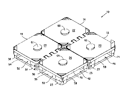
FIG. 1 is a perspective view of a pallet of
the present invention illustrated by four interlocked
sections;
FIG. 2 is a view of one section of the
pallet of FIG. 1;
FIG. 3 is view of the pallet shown in FIG. 1
in a partially broken down state:
FIG. 4 is a view of another embodiment of
the present invention illustrated by two interlocked
sections: and
FIG. 5 is a view of one section of the
pallet of FIG. 4.
DETAILED DESCRIPTION OF THE PREFERRED EMBODIMENT
Referring to Figure 1, pallet 10 is
comprised of four sections 12, 14, 16 and 18. Each of
the four sections is substantially identical having a
top load supporting deck 20, 22, 24 and 26 and foot

2087440
WO 92/01607 PCT/US91/04887
3
members 21, 23, 25, 28, 30, 32 and 34 at the corners
of each section.
Section 12 is shown in more detail in Figure
2. Knuckles 36, 36' and 36" are spaced apart along
the periphery of the surface of deck 20. Similar
knuckles 38, 38' and 38" are spaced apart along
stringer 40. The knuckles have eyes 42, 42', 42", 44,
44' and 44" for receiving locking members. Sections
14, 16 and 18 include similarly spaced knuckles and
eyes.
As shown in Figure 1, the sections have
openings 46, 48, 50 and 52 which are wide enough to
permit entry of the forks of a fork-lift or pallet
truck. Stingers 54, 56, 58 and 59 have beveled outer
and interior surfaces, preferably beveled at a 45
degree angle, to permit easy access and withdrawal of
the wheels of a pallet truck.
The embodiments shown in the Figures are
configured to transport large rolls of film. As shown
in Figure 1, nodes 60, 61, 62 and 64 protrude from the
surface of the sections. An open end of the core of a
roll in an upright position is placed over the node to
assist in retaining the roll on the pallet. The node
as well as the surface of the section should be
suitably reinforced for supporting heavy loads. Other
cc~figurations could be used to accommodate
di~ferently shaped loads.
As best shown in Figure 2, the surface 20 of
section 12 includes wells 66, 68 and 70 for receiving
corner posts. A triangular shaped post 72, a portion
of which is shown, or other configuration may be used.
The posts can support a cover plate, not shown, which
would include nodes for receiving the open end of the
core of a roll standing on the pallet. A cover plate
is necessary to protect the rolls on the pallet during

WO 92/01607
PCT/US91 /0488'
4
shipping and stacking. A stretch-wrap package can be
provided for encasing the pallet, rolls and the cover
plate using a suitable polymeric film.
Referring now to Figure 3, pallet 12 is
shown in a partially broken down state. Locking rod
74 is shown partially inserted through the knuckles of
adjoining sections 16 and 18. A second locking rod 76
is also shown partially inserted through knuckles on
sections 14 and 18. When rod 74 is fully inserted,
bent end 78 fits into groove 80 which is formed
between sections 16 and 18. A similar groove
accommodates the end of rod 76.
In another embodiment of the pallet of this
invention shown in Figure 4, sections 82 and 84 have
knuckles 86, 86', 86", 88, 88' and 88" spaced along
the periphery of decks 90 and 92. Rod 94 is shown in
the locking position securing the sections together.
Section 82 is shown in more detail in Figure
5. A second set of knuckles 98, 98' and 98" is shown
on underlying stringer 100. When two sections are
mated, locking rods can be inserted in both the upper
and lower sets of knuckles. The surface of the deck
102 of section 82 is configured with nodes 104, 106,
108, 110 and 112 to receive the hollow end of cores of
rolls of film.
The pallets of this invention may be
constructed from a variety of materials. They may be
molded from polymeric materials such as ABS resins,
high density polyethylene and polyesters. Recylcable
material are particularly suited for this purpose. In
molding the pallets the deck portions and the lower
portion which includes the stringers and foot members
can each be molded separately and joined together by
suitable fastening means. Preferably, the foot
members and stringers are molded simultaneously as

WO 92/01607 ~ ~ 3 ~ ~ ~ ~ PCT/US91 /04887
contiguous members. However, the sections of the
pallet may be molded as integral units. Various known
molding techniques can be used.
While particular embodiments of this
5 invention have been shown and described, it will be
apparent to those skilled in the art that various
changes and modifications may be made therein without
departing from the scope of the invention.
15
25
35

Dessin représentatif
Une figure unique qui représente un dessin illustrant l'invention.
États administratifs

2024-08-01 : Dans le cadre de la transition vers les Brevets de nouvelle génération (BNG), la base de données sur les brevets canadiens (BDBC) contient désormais un Historique d'événement plus détaillé, qui reproduit le Journal des événements de notre nouvelle solution interne.

Veuillez noter que les événements débutant par « Inactive : » se réfèrent à des événements qui ne sont plus utilisés dans notre nouvelle solution interne.

Pour une meilleure compréhension de l'état de la demande ou brevet qui figure sur cette page, la rubrique Mise en garde , et les descriptions de Brevet , Historique d'événement , Taxes périodiques et Historique des paiements devraient être consultées.

Historique d'événement

Description Date
Le délai pour l'annulation est expiré 2010-07-19
Lettre envoyée 2009-07-17
Inactive : CIB de MCD 2006-03-11
Accordé par délivrance 2001-09-11
Inactive : Page couverture publiée 2001-09-10
Lettre envoyée 2001-05-17
Exigences de modification après acceptation - jugée conforme 2001-05-17
Inactive : Taxe finale reçue 2001-04-18
Modification après acceptation reçue 2001-04-18
Inactive : Taxe de modif. après accept. traitée 2001-04-18
Préoctroi 2001-04-18
Lettre envoyée 2001-01-05
Un avis d'acceptation est envoyé 2001-01-05
Inactive : Approuvée aux fins d'acceptation (AFA) 2000-12-11
Inactive : Lettre officielle 1999-02-26
Inactive : Dem. traitée sur TS dès date d'ent. journal 1998-08-07
Inactive : Acc. réc. RE - Pas de dem. doc. d'antériorité 1998-08-07
Inactive : Renseign. sur l'état - Complets dès date d'ent. journ. 1998-08-07
Toutes les exigences pour l'examen - jugée conforme 1998-07-13
Exigences pour une requête d'examen - jugée conforme 1998-07-13
Demande publiée (accessible au public) 1992-02-06

Historique d'abandonnement

Il n'y a pas d'historique d'abandonnement

Taxes périodiques

Le dernier paiement a été reçu le 2001-06-26

Avis : Si le paiement en totalité n'a pas été reçu au plus tard à la date indiquée, une taxe supplémentaire peut être imposée, soit une des taxes suivantes :

  • taxe de rétablissement ;
  • taxe pour paiement en souffrance ; ou
  • taxe additionnelle pour le renversement d'une péremption réputée.

Les taxes sur les brevets sont ajustées au 1er janvier de chaque année. Les montants ci-dessus sont les montants actuels s'ils sont reçus au plus tard le 31 décembre de l'année en cours.
Veuillez vous référer à la page web des taxes sur les brevets de l'OPIC pour voir tous les montants actuels des taxes.

Historique des taxes

Type de taxes Anniversaire Échéance Date payée
TM (demande, 6e anniv.) - générale 06 1997-07-17 1997-06-19
TM (demande, 7e anniv.) - générale 07 1998-07-17 1998-06-17
Requête d'examen - générale 1998-07-13
TM (demande, 8e anniv.) - générale 08 1999-07-19 1999-06-15
TM (demande, 9e anniv.) - générale 09 2000-07-17 2000-06-23
2001-04-18
Taxe finale - générale 2001-04-18
TM (demande, 10e anniv.) - générale 10 2001-07-17 2001-06-26
TM (brevet, 11e anniv.) - générale 2002-07-17 2002-06-17
TM (brevet, 12e anniv.) - générale 2003-07-17 2003-06-19
TM (brevet, 13e anniv.) - générale 2004-07-19 2004-06-16
TM (brevet, 14e anniv.) - générale 2005-07-18 2005-06-07
TM (brevet, 15e anniv.) - générale 2006-07-17 2006-06-07
TM (brevet, 16e anniv.) - générale 2007-07-17 2007-06-07
TM (brevet, 17e anniv.) - générale 2008-07-17 2008-06-10
Titulaires au dossier

Les titulaires actuels et antérieures au dossier sont affichés en ordre alphabétique.

Titulaires actuels au dossier
E. I. DU PONT DE NEMOURS AND COMPANY
Titulaires antérieures au dossier
WILLIAM BOYD REYNOLDS
Les propriétaires antérieurs qui ne figurent pas dans la liste des « Propriétaires au dossier » apparaîtront dans d'autres documents au dossier.
Documents

Pour visionner les fichiers sélectionnés, entrer le code reCAPTCHA :


Pour visualiser une image, cliquer sur un lien dans la colonne description du document. Pour télécharger l'image (les images), cliquer l'une ou plusieurs cases à cocher dans la première colonne et ensuite cliquer sur le bouton "Télécharger sélection en format PDF (archive Zip)" ou le bouton "Télécharger sélection (en un fichier PDF fusionné)".

Liste des documents de brevet publiés et non publiés sur la BDBC .

Si vous avez des difficultés à accéder au contenu, veuillez communiquer avec le Centre de services à la clientèle au 1-866-997-1936, ou envoyer un courriel au Centre de service à la clientèle de l'OPIC.


Description du
Document 
Date
(aaaa-mm-jj) 
Nombre de pages   Taille de l'image (Ko) 
Revendications 1994-05-13 2 101
Revendications 1998-09-07 2 80
Abrégé 1995-08-16 1 49
Description 1994-05-13 5 178
Dessins 1994-05-13 3 73
Revendications 2001-04-17 2 77
Dessin représentatif 1998-07-29 1 11
Dessin représentatif 2001-08-26 1 13
Rappel - requête d'examen 1998-03-17 1 118
Accusé de réception de la requête d'examen 1998-08-06 1 177
Avis du commissaire - Demande jugée acceptable 2001-01-04 1 165
Avis concernant la taxe de maintien 2009-08-30 1 170
Correspondance 1998-12-07 32 1 385
Correspondance 1999-02-25 2 12
PCT 1993-01-14 16 425
Correspondance 2001-04-17 2 69
Taxes 1994-02-06 1 19
Correspondance 2004-04-29 46 2 876
Correspondance 2004-06-15 1 22
Correspondance 2004-07-13 1 28
Taxes 1994-01-13 1 39
Taxes 1995-06-26 1 90
Taxes 1996-06-03 1 97
Taxes 1994-07-13 1 101