Note: Descriptions are shown in the official language in which they were submitted.
6Y0 92/01964 PC?/US91/05094
-1-
'~~8'~~~9
DECORATIVE GLASS
Field of the Invention
The present invention relates to light-refracting glass, and more particularly
to sheets of decorative glass designed to refract incident light so as to form
an
artistic light pattern on a surface proximate to the glass.
Baek~round of the Invention ,
The use of decorative glass in houses and other structures is well known.
Such decorative glass includes stained or leaded glass windows of the type
comprising a plurality of tinted and clear pieces of glass arranged in an
artistic
pattern. In some cases, the peripheral edge of one or more of the pieces of
glass
is beveled. ,
Under certain light conditions, light rays intersecting the beveled portions
of
discrete glass nieces of a stained glass window will be refracted so as to
form
"light patterns" on a surface, e.g., a wall, positioned near the window. as
used
~ herein, "light patterns" refers to visually discernible patterns formed on a
surface
by a light-refracting device. Such patterns are often slightly darker than the
surface on which they are projected, and under certain circumstances such
patterns may have an intense, dazzling appearance. Under certain conditions,
the
light patterns formed by discrete glass pieces of a stained glass window may
include all or a portion of the visible color spectrum. Light patterns of the
type
formed by known stained glass windows typically lack any identifiable pattern
and
often include discrete light portions which are separated from one another.
Thus,
the overall effect of the light patterns formed by known stained glass windows
is
typically characterized by disarray and absence of recognizable shapes and
2 ~ patterns.
Glass and other sheets of transparent material have been used in window
openings, as well as in conjunction with artificial lighting fixtures, to
diffuse light
incident thereon or to refract and transmit incident light which would
otherwise
WO 92/01964 PCT/U591/05094
~~~g~ 5g~;~
-2-
be reflected. For instance, U.S. Patents Nos. 595,23, 1,277,065, and 1,669,663
disclose light-refracting sheet glass designed to refract, and transmit as
diffused
light, the light rays intersecting the outer surface of the glass. Such glass
includes a plurality of concave or convex sections arranged in a regular
geometric
pattern on one surface of the glass. In addition, the glass sheet disclosed in
U.S.
Patent No. 595,273 is apparently designed to provide such diffusion without
producing the dazzling effect which occurs when light. is refracted by a
conventional prism. U.S. Patent No. 2,859,334 discloses a transparent louver
designed for diffusing light emitted by a fluorescent lighting fixture. One
0 embodiment of the louver comprises a series of lour-sided pyramid-like
projections arranged in a regular geometric pattern, with each of the
projections
being surrounded by an upstanding cvall. To obtain satisfactory diffusion of
the
light generated by the associated fiuorescen: lighting fixture, each of the
projections is about 0.375-inch square. It is also known to provide corrugated
15 transparent sheet material for the purpose of refracting light incident on
one
surface thereof so that objects will apgear distorted when viewed through one
side
of the sheet of material, as disclosed in U.S. Patent No. 1,886,445.
Thus, known stained glass windows and known transparent sheets of material
for refracting light intersecting the material so as to diffuse the light are
not
20 designed for producing artistic light patterns comprising geometric shapes
arranged in discernible order on a surface proximate to the window or sheet.
Obiects and Summary of the Invention
One object of the present invention is to provide a sheet of decorative glass
designed to refract incident light so as to produce a light pattern comprising
25 regular geometric shapes on the surface of a wall proximate to the glass.
Another object of the present invention is to provide a sheet of decorative
glass for refracting light incident thereon so as to produce a plurality of
color
patterns arranged in regular geometric order on a wall positioned adjacent the
glass.
30 These and other objects are achieved by a sheet of decorative glass
comprising a smooth outer surface and a faceted opposite surface. The latter
includes a plurality of projecting sections arranged in regular geometric
order.
Each of the sections includes a plurality oplanar facets. The size and shape
of
each of the facets, as well as the angular inclination of the surface plane of
the
35 facets relative to the opposite, smooth surface of the sheet, are selected
so that
incident light transmitted through the glass will be refracted at the
interface of
each of the facets with the surrounding atmosphere so as to form a plurality
of
~ll~SylT'I~TE S~IEET
VVO 92/0196A PCT/1JB91/05094
-
geometric light patterns arranged in regular order on a surface such as a wall
near, but spaced from, the glass. When the incident light intersects the outer
surface of the glass at certain intensity levels and angular lnelination, the
geometric light patterns will include a color distribution comprising some or
all of
the visible light color spectrum.
Brief Description of the Drawings
FIGURE 1 is a perspective view of the faceted side of the decorative glass
sheet of the present invention;
FIGURE 2 is a plan view of the faceted side of the glass sheet shown in
FIGURE 1;
FIGURE 3 is a plan view of the opposite, smooth side of the glass sheet
illustrated in FIGURE 1;
FIGURE 4 is an end view of the decorative glass sheet shown in FIGURE 1;
and
1 5 FIGURE 5 is an idealized side elevational view of a geometric light
pattern
which will be transmitted by the decorative glass sheet of the present
invention
onto a surface proximate to the glass under certain lighting conditions. ,
Detailed Description of the Invention
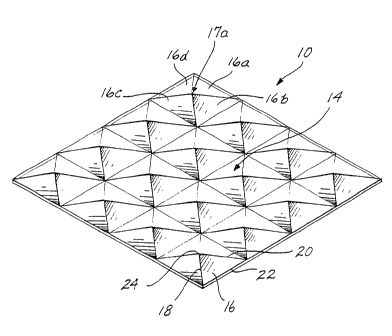
Referring to FIGURES 1-4, the present invention is a sheet 10 of decorative
glass for forming a plurality of geometric light and color patterns on a
surface
proximate to the glass. Sheet 10 comprises a smooth surface 12 and a faceted
opposite surface 14. Typically, sheet 10 is installed in an exterior window
opening
in a house or other structure, although under Certain circumstances it may be
desirable to install sheet 10 in a w inflow opening in an interior wall. Shee
t 10 is
typically installed in .a vertical mode. However, under certain conditions it
may
be desirable ~to install sheet 10 so that its outer surface 12 is positioned
at an
angle to the vertical, e.g., when sheet 10 is installed in a roof ,skylight.
To provide
a projection surface for the desired light patterns, the window opening in
which
sheet 10 is disposed should be positioned near, i.e., 5 to 20 feet away from,
a
surface such as a wall. Ideally, the projection surface should have a light
color,
extend parallel to surface 12 of sheet 10, and be smooth.. Preferably, sheet
10 is
installed so that surface 22 is on the outside, i.e., exposed to incident
light.
Decorative glass sheet 10 is preferably made from a sheet of glass having a
refractive index which is highly uniform throughout the entire sheet.
~5 Additionally, sheet 10 preferably has a relatively high refractive index,
e.g., a
refractive index ranging from 1.50 to _1.70. In this connection, leaded
crystal
optical glass or water white crown optical glass may be satisfactorily
employed as
WO 92/01964 PC1'/US91/OS094
'~,~~Yx ~~L~"
the starting material from which sheet 10 is fabricated. However, when it is
not
important that the light pattern formed by sheet 10 have a predictable
pattern, or
when it is not important that the light pattern include color, glass 10 may be
made
from a sheet of glass having a refractive index as low as 1.45, e.g.,
conventional
optical glass or even plate glass. Sheet 10 may also be made from a synthetic
polymer such as polycarbonate, although the light pattern produced by such a
sheet will typically not be as clearly defined as that produced when sheet 10
is
made from optical glass. Additionally, when sheet 10 is made from a synthetic
polymer, the sheet will often cloud with time as a consequence of the reaction
of
the synthetic polymer with light. Sheet 10, when made from glass, may be
fabricated using a conventional milling o~ grinding machine. Conventional
molding processes may be used to fabricate sheet 10 using synthetic polymers.
To achieve the desired light and color patte:ns, as discussed hereinafter, it
is
preferred that sheet 10 be at least 0.25 inch thick at its portions of
greatest
1 ~ thickness, i.e., those portions of faceted surface 14 spaced the greatest
distance
from smooth surface 12. However, sheet 10 may be somewhat thinner than
0.25 inch at its thickest portions when less than optimal light and color
patterns
are aceegtable. Sheet 10 may be significantly thicker than 0.25 inch at its
thickest portions, for instance, up to an inch or more in thickness, with the
upper
end of the thickness range being limited by cost and weight of the glass from
which sheet 10 is fabricated. To ensure sheet 10 has sufficient rigidity and
structural integrity, it. is important that the thinnest portion of the sheet
be
sufficiently thick. For instance, when sheet 10 is made from optical glass,
the
thinnest portions thereof should have a thickness of at least 0.175 inch.
Faceted surface 14 is deficied by a plurality of facets 16, each of which is .
associated with several other facets so as to form a projecting section I7.
For
instance, projecting section 17a includes facets 16a, 16b, 16c, and I6d (see
FIGURE 1). It is preferred that projecting sections 17 be positioned in
regular
geometric order across sheet 10, although under certain circumstances it may
be
desirable to position sections 17~ randomly across the sheet. As discussed
hereinafter, the specific size and configuration of projecting' sections 17
will vary
as a function of the size, configuration, and angular inclination of facets
16.
Each of the facets 16 is planar and defines an interface surface where
incident. light is refracted, as discussed in greater detail below. As viewed
in plan
(see FIGURES i and 2), facets 16 preferably have a triangular configuration,
although other polygonal configurations may also be employed. When facets 16
have a triangular configuration, the triangle defined by the facet may have an
SIJ~~'T1°~'~.1T~ ~~~E'f ,
dV0 92/01964 PCT/US91/05094
equilateral, isosceles, or other configuration. The number, relative length,
and
angular relation of the sides of facets 16 may vary depending upon the desired
light pattern to be produced by glass 10, as discussed in greater detail
hereinafter. The bottom edges of the facets, e.g., bottom edges 22 of the
triangular facets 16 shown in FIGURE 2, may extend either perpendicular or
parallel to the edges of sheet 10, as shown in FIGURE 2, or may extend
transversely to the side edges (not shown).
To achieve artistically satisfactory light patterns, it is important that the
surface area of each facet 16 be significantly larger than the surface area of
the
1C facets of known transparent sheets of material designed to diffuse light
intersecting the material. Thus, it is preferred that each facet 16 have a
planar
interface surface area of at least 0.45 square inch. Ideally, the surface area
of
facets 16 ranges from 1.'~ to 4 square inches, with even larger surface areas
,
being acceptable when sheet 10 is fabricated from relatively thick, i.e., more
than
1~ I-inch thick, glass sheet. In an exemplary embodiment of the present
invention,
each facet 16 has an equilateral triangle configuration, and each of the sides
of
the triangle is 2.875 inches long. Thus, the total surface area of such facets
16 is
about 3.565 inches.
The plane along which each facet 16 extends is inclined a predetermined
20 angle c (see FIGURE 4) relative to the plane along which smooth surface 12
extends. For instance, as shown in FIGURE 4, facet 16a extends along plane X
whic'n is inclined at an angle a relative to the plane Y along which smooth
surface 12 extends. Depending upon the angular inclination of facets 16
relative
to smooth surface 12, and the angular inclination of the light intersecting
2~ surface 12, either noncolored light patterns or colored light patterns, as
described
in greater detail hereinafter, will be projected by sheet IO onto an adjacent
surface. When it is desirable to form only Iight patterns without color, each
facet 16 may be formed so that the inclination angle 6 (see FIGURE 4) thereof
ranges from as little as 1° up to about 10°. When it is desired
that the light
30 patterns formed by sheet 10 have color disposed therein, the facets 16
should be
inclined so that angle 9 is at least 10°. Depending upon the original
thickness of
sheet 10 and the size of facets 16, the latter may be inclined so that angle 8
is as
great as about 20°. Of course, the surface area of facets 16 and the
inclination
angle 8 of facets 16 are limited by the thickness of the glass from which
sheet 10
3 ~ is fabricated. Consequently, a sheet 10 having relatively large facets,
i.e., facets
having a surface area greater than about 4 square inches, and a relatively
large
facet inclination angle e, i.e., greater than about 14°, must be
fabricated from
~~I d~3
WO 92!01954 PCr/US91/U5094
j~z-~a~ 5a~ _6_
relatively thick glass, e.g., glass having a thickness of 0.75 inch or more.
Preferably, all of the facets 16 in a given sheet 10 are inclined at identical
inclination angles 9. However, under certain circumstances it may be desirable
to
incline certain facets 16 in a given sheet 10 at one inclination angle 9 and
one or
more other groups of facets at different inclination angles.
The embodiment of glass sheet 10 shown in FIGURES 1-4 exemplifies one set
of facet design parameters encompassed by the present invention. The sheet 10
of
this exemplary embodiment was made from a sheet of water white crown optical
glass having a refractive index of 1.57. Prior to the formation of faceted
surface 14, sheet 10 had a thickness of 0.5 inch. Sheet 10 includes sixteen
projecting sections 17 which are arranged in 4x4 configuration. Each
projecting
section 17 comprises four facets 16, each of which has an equilateral triangle
configuration, with side edges 18 and 20 and bottom edge 22 of the facets each
being 2.875 inches in length. Thus, each sheet 10 includes 64 facets 16. Each
of
i5 the four facets 16 of each projecting section 17 has an inclination angle a
of 12°,
whereby each section 17 has a convex, fou~-sided pyramidal configuration.
Thus,
for each projecting pyramidal section 17, the facets 16 thereof are positioned
relative to one another so that the apexes 24 of the facets join one another,
and
the bottom edges 22 of the facets of the section 15 are arranged so as to
define a
square, when viewing the section 17 in plan, measuring 2.875 inches on a side.
In the embodiment of sheet 10 illustrated in FIGURES 1-4, the sheet has a
thickness of about O.I94 inch, as measured at the thinnest portion thereof
(e.g., at
the bottom edge 2Z of each of the facets 16), and the distance between the
apex
of the pyramidal sections 17 and smooth surface 12, as measured along an axis
extending perpendicular to smooth surface 12, is 0.306 inch. The bottom edges
22
of the facets 16 of one pyramidal section 1'r are contiguous with the bottom
edges
of adjacent pyramidal sections, or the edges of sheet 10, as the case may be,
and
the bottom edges of the facets extend either parallel or perpendicular to the
side
edges of sheet 10, as the case may be.
30 Referring now to FIGURES 1-5, the specific light and color pattern formed
by sheet 10 will vary significantly depending upon the number and arrangement
of
projecting sections 17, and the size, configuration, number, and inclination
angle r
of the facets 16 in the projecting sections,. and the intensity and angular
relation
of the .light intersecting surface 12 of sheet 10. However, by way of example,
3 ~ when the decorative glass sheet 10 illustrated in FIGURES.1-4 and
described
above is installed in the vertical position in an exterior window opening
positioned
about 10 feet away from a vertically extending wall, with the window opening
~l.l~~'t°I"1"lJ't~ SI-9~t"r
1~0 92/01964 PCT/US91/05094
being positioned to receive southern sun exposure, a light pattern 40 similar
to the
one illustrated in FIGURE 5 will be formed on the wall during certain times of
the
day. Light pattern 40 comprises a plurality of readily discernible triangular
shapes 42 which have an intense, dazzling appearance. Triangular shapes 42 are
7 arranged in groups of four in rows 44. )aach row 44 of triangular shapes 42
is
positioned in a group 46 comprising four rows of triangular shapes positioned
one
on top of the other. Light pattern 40 includes four groups 46, each of which
is
positioned in mutually orthogonal relation to adjacent groups. Thus, under
satisfactory light conditions, light pattern 40 includes 64 discrete
triangular
shapes 42, one for each of the facets 16 in sheet 10. The specific size of
triangular shapes 42 will vary depending upon the intensity and angular
inclination
of the light intersecting surface 12. However, under one set of light
conditions,
triangular shapes 42 had a substantially equilateral triangle configuration,
with
the sides of the triangular shape each measuring about 5 inches in length.
Depending upon the intensity and angular inclination of the incident light,
i.e., the light intersecting surface 12, facets 16 may disperse the incident
light so
that one or more of the triangular shapes 42 will include a color distribution
disposed within the periphery thereof comprising some or all of the visible
color
spectrum. Under optimal conditions, the entire visible color spectrum will be
present in each triangular shape, with the red end of the spectrum being
positioned adjacent the base 48 of the triangular shapes 42, the purple end of
the
spectrum being 'positioned adjacent the apexes 50 of the shapes 42, and the
intermediate colors being positioned in between. Under less than optimal light
conditions, none, or only a por tion, othe color spectrum will be present in
2 ~ triangular shapes 42.
As the intensity and angle of inclination of the incident light changes, one
or
more of the shapes 42, rows 44 of shapes 42, or even groups 46 of rows 44 may
disappear. Furthermore, rows 44 will move radially toward or away from one
another as a function of the intensity and angular inclination of incident
light. In
addition, the size of the discrete shapes 42 will change with changes in the
intensity and angular inclination of incident light.
Light pattern 40 is created by sheet 10 in accordance with well-known
optical principles. Thus, light intersecting smooth surface 12 at less than
the
critical angle is refracted at the interface (i.e., surface 12) between sheet
10 and
the surrounding atmosphere and transmitted through sheet 10 toward faceted
surf ace 14. As those of ordinary skill in the ar t will appreciate, the
critical angle
for a given sheet 10 will vary depending on the refractive indices of the
sheet and
~~~~T'~~~~ ~~iL~
!VO 92/01964 PCT/US91/05094
_8_
the surrounding atmosphere. Light rays which have been transmitted through
sheet 10 so as to intersect the facets 16 of surface 14 at less than the
critical
angle will be refracted at the facets, each of which constitutes a planar
interface
surface, and transmitted out of sheet 10 toward the wall or other surface
positioned nesr the sheet. Light rays intersecting interface facets 16 at
greater
than the critical angle will be reflected back into sheet 10 and ultimately
refracted at either surface 12 or 14 so as to pass out of sheet 10, or
absorbed by
the frame surrounding the edges of the sheet.
Sheet 10 will disperse the light intersecting surface 12, which light
typically
includes the entire color spectrum, into discrete colors as a function of the
wavelength of the light rays in the incident light. Such dispersion occurs as
a
consequence of the refraction described above, and will occur to a greater or
lesser extent depending upon the size and inclination angle 9 of facets 16,
and the
intensity and angle of inclination of light intersecting surface 12.
1~ An important advantage of the glass sheet 10 of the present invention, as
compared to transparent sheets of material designed to diffuse incident light
and
comprising a plurality of small facets (i.e., facets having a surface area of
less
than about 0.45 square inch), is that the light pattern formed by sheet 10
comprises readily discernible, relatively large, discrete light patterns which
have
an intense, dazzling appearance. The light patterns formed by known
transparent
sheets of material, on the other hand, generally have either a uniform,
diffused
appearance, or comprise discrete pinpoints of light lacking discernible
geometric
shapes and having a "busy," aesthetically unpleasing appearance.
Since certain changes may be made in shee t 10 without departing from the
2 ~ scope of the present invention, it is intended that all matter contained
in the
above description or shown in the accompanying drawings shall be interpreted
in
an illustrative and not in a limiting sense.
S1J~~°i"1"1'6,J"~~ ~I~E~T