Note: Descriptions are shown in the official language in which they were submitted.
`` - 2 - 20~7657
"MECHANISM FOR AUTOMATICALLY PREPARIN~ TO COVER THE
CORNERS OF FOLDERS, JACKETS AND THE LIKE FOR T~E PAPER,
BOARD AND ~OOKBINDING INDUSTRY"
DESCRIPTION
The invention re?ates to a method and a mechanism
for neatly covering - as defined more fully below - the
corners of a manufacture of board with the paper glued to
one face of this board and the borders of this paper
projecting from the edges of the board and cut across at
45 a short distance from each corner; after one border
has been folded down over the corresponding edge, the
portion of paper projecting from the two corners must be
tucked in; in this way when the adjacent edge is folded
down, internal folds form around the perimeter of the
board, while the corners are covered well and there is no
cut paper near the corners. This tucking-in operation has
hitherto been performed manually next to the two corners
at the ends of an edge which has just been covered. The
invention relates to a method and mechanism for automati-
cally performing a tucking-in operation to produce neatly
covered corners, as i9 required in certain bookbinding
and other types of work.
The first subject of the invention is a method
for neatly covering the corners of a manufacture of board
with the paper glued to one face of this board and the
borders of this paper projecting from the edges in order
to be folded down over these edges and cover them. In the
invention, as soon as one border has been folded down
over the front edge of the board, the advancing movement,
together with two tools positioned level with the thick-
ness of the board, is used to act on the paper at the
ends of the folded border, in the portions projecting
from the corners of the said edge and thereby create an
inward tuck and a fold, in order to prepare the manufac-
ture for the folding down of the adjacent edge so thatthe corner i9 neatly covered.
.
,,, ,,, , , . , , , ., , . . . .. . . . ~ .... . . . . . . . .. .. . .. . .
~ 3 ~ 2087657
Another subject of the invention is a mechanism
for carrying out this method. The said mechanism basi-
cally comprises two tools positioned level with the
thickness of the board and designed to act on the paper
a~ the ends of a border folded down first to cover the
corresponding edge of the board, in the portion project-
ing from the corners of the said edge; this creates an
inward tuck and a fold in order to prepare the manufac-
ture for the folding down of the adjacent border so that
the corner is neatly covered.
In practice each of the said tools is in the form
of a shaped, an~ularly movable arm forming part of a
rotary element which is stressed elastically to press
upon the corner and upon the edge parallel to the direc-
tion of advance of the board. In an advantageous embodi-
ment, each tool is moved away from the level of the
board, after rubbing along its edge, parallel to the
direction of advance; this removes the tool from the
operation once the inward tuck has been made.
In an advantageous embodiment the border ad~acent
~o the first folded border is drawn by low pressure in
the plane of the paper in order to offer some resistance
to the tucking and thereby make it neater. To this end,
at the corners to be covered, a continuous band may be
provided on whose surface suction is generated by an
underlying low-pressure chamber over which it runs; the
said continuous band is so driven that its upper active
side has a speed equal to the speed of advance of the
manufacture which is being processed. A pressure roller
acting on the manufacture may also be provided to pre~s
it onto the suction band, and thi~ may be raised when not
in use.
~ he invention will be made clearer by the
description and accompanying drawing, which latter shows
a practical, non-restricting embodiment of the said
invention. In the drawing:
Fig. 1 is a perspective view of stages in the
processing of a manufacture by a known machine described
. . . .. ... ... . . .. . . .. . . . . . . .. . . . . .. . . . . . . . . . .. . .. . . .
': ' ' ' .' :
2087~7
in an earlier patent;
Figs 2, 3 and 4 show, in plan with parts removed
and in the views and sections taken through the lines
III-III of Fig. 2 and IV-IV of Fig. 3, such a machine
improved by the invention;
Figs 5, 6 and 7 show an enlarged detail of Fig. 2
and the same detail as it reaches successive positions;
Figs 8 and 9 ~how local views through the lines
VIII-VIII of Fig. 5 and IX-IX of Fig. 7;
Figs 10 and 11 show in isolation a tool according
to the invention in a modified form, in plan and through
IX-IX of Fig. 10;
Figs 12 and 13; and 14 and 15 show in plan and in
side elevation a corner of a manufacture in two stages of
handling;
Fig. 16 shows a perspective view of the ~tage
seen in Figs 14 and 15 and a tool about to act;
Figs 17 and 18 show in a similar fashion to
Figs 12 and 13 or 14 and 15 at a ~ubsequent stage;
Figs 19 and 20 are perspective views of the
corner of the manufacture in the stage seen in Figs 17
and 18 and after co~ering has been completed;
Fig. 21 shows the said corner covered, in plan;
Fig. 22 shows a local section through XXII-XXII
of Fig. 3; and
Figs 23 ànd 24 show, similarly to Figs 5 and 8,
an alternative embodiment.
As shown in Fig. 1, a board S of a certain
thickness iR to be co~ered with a paper L, which is glued
to one face of a board S and has border~ Ll, L2, L3 and
L4 projecting from the edges of the board for the purpose
of covering the said edges by being folded down over the
edge and glued to the margin of the opposit~ face of the
board. Using a machine fitted with brush tools indicated
by 1 and 3, rotating in the directions of arrows fl and
f3, as already known per se - see prior Italian patents
9411 A/90 and FI9lA 63 (European Patent Application
91830220.3) and FI9lA 145 (European Patent Application
.
~ ~ .
- 5 - ~087657
92830315.5) - and with the manufacture advancing in the
direction of the arrow fA, the first border L1 is folded
down by the brush rotor 1 and then, with the manufacture
advancing in the opposite direction, i.e. in the direc-
tion of arrow fB and by means of the brush rotor 3rotating in the direction of arrow f3, the border L3 of
the paper is folded down.
The object of the invention is to ensure complete
covering of the corner A of the board S - which is
generally quite thick - so that the thick edge of the
board cannot be seen in the finished manufacture and also
in order to avoid the possibility of the paper covering
L being torn by the exposure of a cut edge of the said
paper at one of the corners of the manufacture, and also
to prevent portions of the paper from projecting, even if
folded.
Covering (Figs 12 to 21) is done as normal by
folding the border L1 through 180 to cover the edge B1
of the thickness S of board, th~ paper L being cut as
shown at LD at 45 and the board S being applied to the
paper such that its corner A is slightly removed from the
diagonal cut LD at this corner of the paper. In this way
- as seen in the sequence of Figs 12 to 21 - after the
border L1 has been folded down over the edge B1 of the
board S (Figs 14 to 16) an inward fold must be created in
the portion LX indicated in Figs 14 to 16 to obtain the
appearance of the corner as indicated in Figs 17, 18, 19,
after which the border L2 i9 folded down over the edge
B2, in such a way that the corner A of the board S is
3Q completely covered in a properly finished manne~, as
shown in Figs 20 and 21, with no gaps in the covering
around the corner A of the board S, no projecting pieces
of paper and no cut edges of paper L in the area around
the thickness of the board S, which are liable to become
damaged during use. As shown in Figs 20 and 21, the
portion LX (indicated in Figs 14 to 16) is pushed in as
indicated by LY (Figs 17 to 19) and the fold LZ is
formed; next, by folding the border L2, a complete
.... .
" .....
- 6 - 20876~7
covering of the corner A of the board is formed, with the
crease LZ of the border L2 which remains within the
perimeter of the manufacture; an optional further
covering LK (Fig. 20), applied to the opposite board face
to that covered with the paper L, completely covers the
cut parts of the borders L1 and L2.
The invention makes it possible automatically to
perform the inward fold indicated by LY of the portion ~X
(as indicated in Figs 14 to 19) and the fold LZ, in such
a way that subsequent folding down of the border L2 -
even if automatic - ensures that the thickness S is
covered neatly at the corner A with the crease LZ at a
distance ~rom the edges and corner of the board, as shown
in Figs 20 and 21.
The invention is embodied - according to the
example illustrated - by a machine which comprise~ the
brush rotors such as 1 and 3, and other components
described in more detail below in the detailed descrip-
tion of the machine, which machine i9 fitted with the
device of the invention for carrying out the folding and
the neat covering of the corner of the board S. Various
functional parts are shown from the conventional machine
in addition to the two brush rotors 1 and 3 mentioned
above. A continuous belt conveyor 5 passes round, among
other elements, a cylinder 7 and is supported by an
internal supporting bar 9, against which is a forwarding
cylinder 10 which is at a slight and adjustable distance
: from the active upper surface of the continuous conveyor
5, this distance bein~ dependent on the thickness of the
board S joined to the paper L and forwarded in the
direction of arrow fA by the conveyor 5 to be pinched
between the conveyor 5 lying on the bar 9 and the for-
warding cylinder 10. The supporting plane of the upper
active surface of the conveyor 5 interacts with the lower
portion of the flexible bristles of the brush rotor 1,
turning in the direction of arrow fl. 12 and 14 indicate
: the two cylinders of a pair of cylinders located down-
stream of the brush rotor 1 relative to the direction of
,, , . . , . , . . .. , ., .. . . . .. ...... ~ . . , . .. .. . . . .. . . , . .. .. , .. ..... ... . . _ . . . . . .. .. .
~" ... ..
_ 7 _ 2~87g~7
- advance fA of the manufacture being processed. The
bristles in the lower portion of the brush rotor 1 act on
the border Ll and fold it down over the edge Bl of the
board S as it passes under this brush rotor 1, and the
pair of cylinders 12, 14 compresses the border Ll onto
the board S face opposite that to which the paper cover-
ing L has been glued, the border Ll being provided with
glue with the same distribution as for the gluing of the
paper L against the board S. The manufacture undergoing
processing reaches a continuous air-permeable band 15
which passes round a cylinder 16 and small cylinders 16A;
the active upper side of said band 15 passes closely over
an underlying low-pressure chamber 17; a pressure roller
16C also acts on the band 15. The manufacture is then
discharged in the direction of arrow f16 until it drops
onto the upper active side of a second continuous con-
veyor 18 whose active upper surface moves in the direc-
tion of arrow fB for the folding down of the second
border L3; 20 indicates lateral guide plates for con-
trolling the free fall of the manufacture in the direc-
tion of arrow fl6 from the forwarding plane - defined by
~ the conveyor 5, the cylinders 12, 14, the band 15 and the
: roller 16A used in the first operation in which the
border Ll is folded and glued - onto the conveyor 18.
After falling in a controlled manner onto the continuous
conveyor 18, the manufacture is forwarded in the direc-
: tion of the arrow fB by the said conveyor under a
cylinder 22 similar to the cylinder 10 in order to reach
the brush rotor 3, which works like t~e rotor 1 against
the conveyor 18 which passes around a return cylinder 24,
until the manufacture has been forwarded between two
cylinders 26 and 28 (similar to 12 and 14) which compress
and stabilise the gluing of the border L3 folded down by
the brush rotor 3 onto the corresponding edge of the
board S. A subsequent air-permeable continuous band 29
passing around a cylinder 30 and small cylinders 30A, a
low-pressure chamber 31 and a pressure roller 30C are
f provided downstream o~ the cylinders 26 and 28 to guide
.~ .
~ - 8 - 2087~57
the subsequent path of the manufacture through the
subsequent processes, which may be the folding down of
the other two borders L2 and L4 in similar operations to
- those indicated above in relation to the folding of the
borders Ll and L3.
For the purpose of automatically carrying out,
during the movement of the manufacture inside the mechan-
isms described above for the folding of the borders Ll
and L3 over the corresponding edges of the board S, the
inward folds as indicated by LY of the portion LX of the
borders Ll, L2 and corresponding edges, and the folds LZ,
for the purposes already indicated, there is provided at
the sides of the board S and against each border parallel
to the direction of advance - as borders L2 and L4 - a
mechanism as described below, both after the passage
through the cylinders 12, 14 and after the passage
through the cylinders 26, 28.
Referring in the drawing to the second path which
the manufacture must follow in the direction of arrow fB
in the second passage as described with reference to Fig.
2 for the folding of the border L3, a device as described
below is applied to the machine on each side of the path
of the manufacture.
The device, which is located on the left-hand
side when viewing Fig. 4, comprises a block 32 in which
a through seat 34 (see also Fig. 8) is formed with a
vertical axis. Mounted in this seat on bearings 36 (shown
diagrammatically) is a small cylinder 38 capable of
angular movement, which small cylinder receiveq the
restoring force of a spring 40 which stresses this small
cylinder in the direction of arrow f38. Mounted on
further bearings 42 (also shown diagrammatically) in the
seat 34 is an angularly movable and axially slidable
spindle 44 belonging to a rotary element 46 to which
there also - and in particular - belongs a shaped arm 48;
this arm 48 is the tool for forming the inward fold LY
and the fold LZ in the portion LX in the two borders
meeting at a coxner A, such as the borders L1 and L2
2~87~7
shown in Figs 12 ff, for the purposes indicated. The
rotary element 46 o~ the spindle 44 and of the shaped arm
48 is axially slidable and angularly coupled - by means
of a tongue 50 - to the small cylinder 38 and is stressed
upwards by a spring 52. To oppose and control the upward
axial movements of the rotary element 46 (44 and 48), a
push element 54 is provided whic~ acts on the upper
transverse surface of the rotary element 46 in its axis
of rotation; the push element 54 is controlled by an
electromagnetic or fluid - especially pneumatic - servo-
control system indicated as a whole by 56 and capable,
via the push element 54, of lowering the rotary element
46 (44, 48) into the position shown in Fig. 8, where the
shaped arm 48 is generally level with the board S moving
lS in the direction of arrow fB, whereas when the servo-
control 56 allows the push element 54 to rise, the rotary
element 46 (44, 48), stressed by the spring 52, follows
(or causes) the rising of the push element 54 and moves
into a raised position as shown in Fig. 9. Pivoting at
57A on the servo-control body 56 is an arm or double arm
57 which carries the pressure roller 30C. A servo-control
58 acts on the arm 57 of the roller 30C simultaneously
with the command from the servo-control 56 on the push
element 54. A similar arrangement is provided for the
control of the roller 16C. Combined with the mechanism
described and in particular with the block 32 is an
optical photocell target indicated diagrammatically by
the components 59 and 60. Its ray R may be intercepted by
the manufacture advancing in the direction of arrow f~,
after the manufacture haq passed the cylinder 30. The
case of the Yervo-control 56 i8 supported by the block
32, for example on ar. upward extension 32A of thi~ ~lock.
On the side of the case of the servo control 56, on a
bra~ket 62, two wheels 64 and 66 are carried, the first
of which operates on the upper surface of the block 32
and the second on the cylinder 30 at the exit of the
folding unit; the said wheels 64 and 66 are designed to
guide the manufacture correctly even at the end of its
:
,
20`87~5`~
-- 10 --
path past the pair of cylinders 26 and 28.
Fixed to the case of the servo-control 56 is a
strip-type bracket 68 shaped as shown in the drawing to
present its section 68A (see also Fig. 22) in such a way
as to act on the bristles of the brush rotor 3 in the
lower portion of the trajectory of the said bristles; the
said terminal section 68A of the strip-type bracket 68 is
active in the path taken under the brush xotor 3 both of
the edge of the board S parallel to the direction of
advance (as directions fA and fB) and of the correspond-
ing border that runs parallel to the direction of advance
of the developing manufacture, such as borders L2 and L4.
In this way the brackets 68, 68A, which are arranged
against each of the lateral edges of the advancing board
S, prevent - as seen in Fig. 22 - the bristles of the
rotor from acting on the borders (as borders L2 and L4)
parallel to the direction of advance of the developing
manufacture and from deforming these borders and also
from becoming soiled with glue picked up from the border
on which the glue is spread; this also avoids the possi-
bility of detachment of the paper from the lower face of
the board S to whiah the paper is glued. The bracket 68
i9 provided on the block of the servo-control 56 against
each of the two borders parallel to the direction of
advance, as borders L2 and L4 mentioned above.
One of the two edges, parallel to the direction
of advance, of the board S of the developing manufacture
is advantageously in a fixed lateral position relative to
the front of the machine, which front extends across the
maximum dimension possible for the developing manufac-
tures Since there is a pair of mechanisms such as the
mechanism comprising a block 32, a servo-control 56 and
a bracket 68, 68A for both brushes 1 and 3, the position
of one of the blocks 32 (for example that on the left
when viewing Fig. 4) is kept fixed, together with its
associated bracket 68 at one of the two extremes of the
useful working front of the machine ~in the lower extreme
as seen in Fig. 2, i.e. the right-hand extreme in the
~' .
. ,
,
`20`87~
11
direction of advance of arrow fB) while the position of
the mechanism (comprising a blo~k such as block 32 and
its associated bracket such as bracket 68, 68A) can be
adjusted - according to the width of the manufacture being
formed - relative to the opposite extreme of the working
front, i.e. the upper extreme when viewing Fig. 2 and the
right-hand extreme when viewing Figs 3 and 4. In Figs 2
to 4, the number 332 indicates the two blocks, 356 the
servo-controls and 368 the two bracket~ associated with
this extreme; 3~9 indicates the continuous band symmetri-
cal to band 29 (the band symmetrical to band 15 is not
shown) which acts in combination with the complex 332,
356, 368; 330C indicates the roller symmetrical to roller
30C and carried by an arm 357 symmetrical to arm 57. 430
indicates a cylinder around which the band 329 runs; the
cylinder 430 is mounted on and driven on the extension
30Z of the cylinder 30, for the purposes indicated below.
The two blocks 332 with their related parts are ad~ust-
able along guide means parallel to the brushes, in ordere
to be movedl for example, from the extreme position 332
indicated by the solid line to a closer position for a
reduction of the front a~ denoted by the broken line at
332A (and the brackets in position 368A) in Fig. 2. The
setting must be equal for the two units 332, 368; ad~ust-
ment is accordingly by means of thrèaded bars 334 driven
simultaneously by a chain drive 336 (Figs 2 and 4)
operated via a handwheel 338 or via electric motors; the
two threaded bars 334 engage in threaded bushes in the
respective blockR 332 enabling them to be operated, these
block~ being guided both on the bars 334 and on bars 340
which guide the sliding movement. The strip-type
brackets, 368, 368A (corresponding to brackets 68) are
therefore ad~usted for position via the handwheel 338 to
adopt the position corre~ponding to the border parallel
to the direction of advance, to suit the transverse
dimension of the developing manufacture. It is thus
possible to ensure the efficiency of the shaped arm 48
relative tn the blocks 332 and the efficiency of the
- 12 - 20876~7
active part 368A o~ the brackets 368 corresponding to the
brackets 68A already described, whatever the dimension of
the developing manufacture transversely to its direction
of advance for the folding of the first two borders -
that is L1 and L3 - lying across its direction of advance
under the brush rotors 1 and 3.
The bands such as band 329 are moved transla-
tionally so as to follow the transverse position at which
the blocks such as block 332 are set, inasmuch as the
cylinder 430 around which the belt 329 runs is coupled in
rotation to and slidable on the narrower section 30Z of
the cylinder 30; the cylinder 430 is driven - in an
obvious way though not shown - by the block 332 during
setting; the rollers 330A are carried by the blo~k 33~.
Thus the bands 329 (and equivalents) are moved with the
setting of the working front width.
The bands 15 and 29 (and adjustable bands such as
329), owing to the suction produced by the low-pressure
chambers such as chambers 17 and 31, cause the longitudi-
nal borders (such as border~ L2 and L4) to stick to thesebands, which advance at the speed of the manufacture; the
action of the tools - such as tools 48 - which cause the
tucking-in of the portions LY and the folding LZ, is
thereby kept under control, though not obstructed, since
the suction exerts an efficient but gentle holding action
which the tools - such as tool 48 - can overcome on the
portion LX, as previously described.
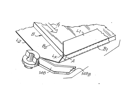
The shaped arm 48 of each mechanism can with
advantage be modified as shown in Figq 10 and 11 and
indicated by 148. It is shaped so as to have two sections
at an angle with each other, with a lower edge 148A and
a rounded end 148B, with which it is possible to carry
out the action on the portion LX of the paper folded down
as shown in Figs 14 to 16, so as to make the deformation
LY and the fold LZ, reaching the position shown in
Figs 17 to 19. The improved shape of the tool 148 effec-
tively ena~les it to act on a ~irtually complete range of
co~er papers.
,
- 13 - 20876~7
Through the action of the springs 40, the arms 48
or 148 of the rotary elements 46 are inclined in the rest
position as shown in Figs 2, 5 and 16, when the edge L3
is worked by the advance in the direction of arrow fB,
the border L3 having been folded down as shown in Figs 14
to 16. In the position shown in Figs 3, 5 and 8 the arm
48 or 148 is lowered by the action of the push element 54
and hence of the servo-control 56, in such a way that it
comes level with the thickness of the board S, but
slightly higher than the paper L and border L2 in a
position in which it will be struck by the corner A of
the board S covered by the border L3, or, in the position
shown in Figs 14, 15 and 16, by the border Ll. Advancing
from the position in Fig. 5 in the direction of arrow fB,
the corner 148A of the shaped arm 48 or 148 commences its
own action on the portion LX of the paper while the arm
148 is gradually moved by the corner A and by the thick-
ness of the advancing board S around the axis of the
spindle 44 in the opposition direction to arrow f38,
until it~ rounded end 148B is pressing against the edge
B2 of the board S as shown in Figs 6 and 17, having
yielded elastically by the yielding of the spring 40,
thus moving from the position shown in Fig. 5 to the
position in Fig. 6; it is during this passa~e that the
inward tuck LY and the fold LZ are formed as shown in
Figs 17, 18 and 19, thus preparing for the covering as
shown in Fig~ 20 and 21 by the subsequent folding of the
border L2. These operations are made smooth by the gentle
holding action of the vacuum produced along the longi-
tudinal borders L2 and L4 through the bands such as bands
15, 29 and 329, while the bands advance in company with
the manufacture. The pressure rollers such as pressure
rollers 30C and 330C - acting on the board joined to the
paper ~whose borders are folded down as they pass through
the machine) - hold the manufacture against the bands.
After the contact with the corner A, that is after the
position shown in Fig. 6 of the manufacture advancing in
the direction fB, has been passed, the push element 54
. ..... ..... ... ... .. .. . . . . . . ..... ., . . ., . . _ . .. . . . .
2~8765~
- 14 -
and 354 is permitted by the servo-control 56 and 356 to
rise so as to allow the rotary element 46 to rise under
the action of the spring 52, from the position shown in
Fig. 8 to the position shown in Fig. 9; the arm 48 or 148
is consequently free from pressing on the edge B2 o~ the
board S and as it lifts clear of thP plane of the board
the spring 4~ restores it to the inclined position shown
in Fig. 7 which corresponds to that in Fig. 5, i.e. ready
for a new operation of folding the paper from position LX
to position LY, LZ as described, under the action of the
servo-control 5S which lowers the rotary element 46 after
the manufacture has passed through~ Simultaneously with
the action of the servo-control S6 and 356, the servo-
controls such as 58 lower and raise the rollers such as
rollers 30C and 330C.
~ hen the edge L2 in turn is folded down by the
machine (either by reinsertion of the manufacture rotated
through 90 relative to its two previous passes through
the machine or by providing a machine which folds the
borders L2 and L4 after the folding of borders L1 and L3
in the manner described) this folding of the border L2
over the corresponding edge B2 of the board S results in
the manufacture being covered at the corner A, as shown
by the change from the conditions shown in Figs 17 to 19
to the conditions shown in Figs 20 and 21, that is with
the crease LZ slightly away from the corner A and from
the edges of the board and extending over the opposite
~ace to that covered by the paper L. In this way the edge
of the board is neatly covered at the corner A and
projection~ of part of cut or folded qheet in the por-
tions facing the perimeter of the manufacture are
avoided. With the optional cove~'ng of the oppoæite face
to that covered by the paper L, using a sheet LK as shown
in Fig. 20 of slightly smaller dimensions than the board,
a complete covering of the board S is achieved without
irregularities, as is required in certain kinds of high-
quality bookbinding work. The command to raise the push
elements such as push elements S4 and 354 and the rollers
'
-
l5 2~87657
such as rollers 30C and 330C, may be sent to the servo-
controls such as servo-controls 56, 356, 58, 358, by the
target represented by the ray R of the photoelectric cell
system 59, 60 already described, or by some other equiva-
lent system.
With the arrangement for the setting of the
blocks 332, strip-type brackets 368 and bands 329 in the
manner indicated, it is possible quickly to prepare the
machine for processing manufactures of different formats
as far as the dimension in the direction perpendicular to
that of advance indicated by arrows fA and fB in the
drawing in concerned.
~ igs 23 and 24 show an alternative embodiment
which relates to the system for controlling both vertical
and horizontal movements of the lever tools such as tools
48. The purpose of this embodiment is to simplify access
to the parts of the machine by moving to the top the
mechanism for producing vertical and horizontal movements
of the tools used to act on the corner covering paper. In
Figs 23 and 24 the numbers of parts corresponding to
tho~e from the previous example are simply increased by
500.
Under the bands such as band 529 and in a block
532 only one tensioning rotary element 601 is provided,
~5 which acts on one of the rollers 530A which is a tension
roller for the band 529. Above the area through which the
developing manufacture passes is a unit S56 which carries
the strip-type brackets 568 and forms a seat for bearings
603 on which is mounted a rotary element 605 that can be
moved on a vertical axis. This rotary element 605 carries
at its lower end an attached block 607 with a through
hole which is internally splined to turn a splined shaft
609 while allowing it to slide vertically; the bottom end
of the haft 609 carries the tool 548. The shaft bO9
; 35 receives an upward force from spring means 611; against
the action of these spring means 611 there acts a pneu-
matic control system with a pipe 613 leading into the
cavity 615 of a cylinder and piston system formed in the
.. . . . . . . . . . . . ................. .. ... . . . . . . ..
.
- 16 - 20876~7
rotary element 605 and comprising a piston fastened to
the top end of the shaft 609; pneumatic control thus
lowers the tool 548 into the active position. A spring
540 acts between the angularly mov~ble rotary element 605
and an anchor point 619 fastened to the unit 556; in this
way the said rotary element and hence the shaft 609 and
the tool 548 are stressed in the same way as the tool 48
was stressed by the spring 40 in the previous example,
performing the same function. Engaged on the unit 556 is
also an actuator 558 which is intend~d to operate the
support arm 557 for the roller 530C acting on the advanc-
ing manufacture to press it onto the active upper side of
the band 529.
The arrangement shown in Figs 23 and 24 transfers
everything relating to the driving of the tool 548 above
the tra~ectory of the developing manufacture, allowing
easier access for maintenance and the like.
It will be understood that the drawing shows only
an embodiment given purely as a practical demonstration
of the invention, it being possible for the said inven-
tion to vary as regards shapes and arrangements without
thereby departing from the scope of the concept underly-
ing the said invention. ~ny reference numbers in the
accompanying claims are for the purpose of facilitating
the reading of the claims with reference to the descrip-
tion and to the drawing, and do not limit the scope of
protection represented by the claims.
For example it is possible to have symmetrical
setting of the blocks 32 and 332 relative to the
longitudin~L mid plane of the muchine.
,, . . . ........ . .. .... ... ~..... . ..... ...... .
,.. .
- ~