Note: Descriptions are shown in the official language in which they were submitted.
2 ~ 76 77 4~134CAN6
ABRASIVE ARTICLE AND METHOD
TECHNICAL FIELD
This invention relates to an abrasive article
and a method for making the abrasive article.
Specifically, the invention involves a plurality of
abrasive sheet members that are connected in a row, which
row may be Z-folded to produce an abrasive article.
BACKGROVN~ OF THE INVENTION
Rotary and orbital tools are commonly used in
conjunction with an abrasive member to abrade material
from a workpiece. Most such tools include a motor, an
output shaft for transmitting the rotary motion of the
motor, and an abrasive member that is attached to the
output shaft. One common abrasive member includes a
single, circular abrasive disk that is mounted on a
backing pad, typically using pressure sensitive adhesive,
hook and loop fasteners, cooperating male and female
threaded members, or the like. After the backing pad and
abrasive member are connected to an output shaft, the
rotating abrasive disk may be urged against a workpiece to
abrade material from the workpiece.
Although single, circular abrasive disks are
popular for some applications, they tend to lack
flexibility near the edge of the disk, which limits their
efficacy under circumstances requiring a more flexible
abrasive. For example, contoured surfaces may be sanded
more effectively with an abrasive member having a flexible
edge than with one having a more rigid edge, so that the
workpiece is not marred or overcut due to edge cutting b~v
a standard circular disk. Edge cutting refers to excessive
abrasion of material from a workpiece due to a stiff
abrasive edge.
An improvement over the single, circular
abras~ve disk is an abrasive sheet member having a main
portion and two or more arm portions radially projecting
from the main portion. The individual abrasive sheet
208~677
-2-
members are typically of substantially identical geometric
configuration (e.q. a main portion and six arm portions,
as in Figure 1; a main portion and two arm portions, as in
Figure 3). As shown in Figure 1, each individual abrasive
sheet member 10 includes opposed major surfaces, one of
which includes an abrasivé coating 12, a body portion 14
and a plurality of arm portions 16 separated from each
other by a constant angle ~ with respect to center point
17. The individual arm portions add flexibility to the
periphery of individual sheet member 10. Further
flexibility may be obtained by forming a plurality of cuts
in each of the arm portions to form a plurality of finger
portions 20. Because the fincJer portions 20 are
collectively more fle~ible than the respective arm portion
would have been without the cuts therein, the abrasive
sheet members are particularly adapted to abrade contoured
profiles with a minimum of edge cutting. The cuts in arm
portions 16 are generally parallel to each other in each
of the arm portions, as shown in Figures 1 and 3.
The individual sheet members may be either a
coated abrasive or a nonwoven abrasive. The former
includes a backing (e.q. cloth, paper, vulcanized fiber,
or polymeric film) with abrasive grains bonded thereto by
one or more binder coats of phenolic resin,
urea-formaldehyde resin, acrylate ~esin, epoxy resin,
aminoplast resin, hyde ~lue, urethane resin, polyester
resin, or a combination thereof. Nonwoven abrasives
include a substrate, which may be a porous, fibrous,
nonwoven construction and an abrasive comprising
individual abrasive particles on one side of the
substrate. An example of such a nonwoven abrasive is U.S.
Patent No. 2,958,593 (Hoover et al.), the contents of
which are hereby incorporated by reference. The abrasive
particles may be made of materials such as fused aluminum
o~ide, ceramic aluminum oxide, heated treated aluminum
oxide, silicon carbide, alumina zirconia, diamond, ceria,
cubic boron nitride, garnet, and combinations thereof.
~87677
--3--
Abrasive sheet members are typically produced
individually in a batch die cut operation, which tends to
be a relatively slow method of production. In order to
produce an abrasive article of suitable size and
durability, a plurality of the abrasive sheet members must
typically be assembled. Each individual abrasive sheet
member has a hole 22 in the center of the main portion,
and several like individual abrasive sheet members may be
collected and thPir respective center holes axially
aligned. After alignment, wh~ch is usually performed
manually, each individual abrasive sheet member is
manually rotated, or fanned out such that the arm portions
of each individual abrasive sheet member are angularly
offset by angle ~, which equals 1/~ of angle ~, with
respect to the arm portions of each immediately adjacent
sheet member, as shown in Eigure 2.
After the individual sheet members have been
collected, aligned, and arranged, they may then be secured
together to form an abrasive article. One type of
releasable fastener that is often used to secure the
collection of individual sheet members includes an arbor
and retainer, as shown with reference to the present
invention in Figure 7. The arbor 190 usually includes a
shaft 192 and a retainer 198 that cooperates with backing
member 194 through the aligned holes to retain the
collection of individual sheet members. Shaft 192 is
adapted to be held by a source of rotary power, and shaft
192 transmits rotary power to the retained collection of
individual abrasive members for abrasive application to a
workpiece.
Alternatively, a permanent fastener (e.g. a
grommet) may be used to hold the individual sheet members
together to ~orm an abrasive article. The abrasiva article
is then retained by an arbor and retainer in much the same
manner as the collection of individual abrasive sheet
members described above. Examples of such abrasive
articles comprising individual abrasive sheet members are
2~87~77
-4-
available under model numbers 93245 and 93251 from
Dynabrade Incorporated of Clarence, New Yor~.
The described method of producing the abrasive
article is both time consuming and costly. The individual
abrasive sheet members must be collected, often by hand,
and their respective holes aligned. This process, in
addition to being a time consuming one, carries with it
the possibility that the holes may be misaligned, which
can render the abrasive article difficult to connect to an
arbor. Once the holes are aligned, each individual sheet
member must be angularly positioned with respect to each
adjacent sheet member to produce the desired abrasive
article. Becau~e the abrasive articles formad from
individual abrasive sheet members may include dozens or
even hundreds of individual sheets, this process is also
costly and tedious. If the individual sheet members are
collected and positioned at the production site, the
higher-cost is passed on to the consumer. However, if the
individual sheet members must be assembled on the job
site, the operator must halt the abrading task while
collecting, aligning, fanning, and securing the individual
sheet members. In view of the time and expense required to
form-an abrasive article according to the prior art, it is
desirable to provide an abrasive article that is easily
assembled and used, as well as a method for forming the
abrasive article.
SUMMARY OF THE INVENTION
According to the present invention, there is
provided an article for abrading a workpiece, comprising a
plurality of like abrasive sheet members. Each abrasive
sheet member includes (i) first and second opposed major
surfaces, at least one of the major surfaces having an
abrasive layer, (ii) a main portion having an aperture
formed therein and a center point, and (iii~ a plurality
of arm portions radially projecting from said main
portion, each respective arm portion perimetrically spaced
from each adjacent arm portion by a constant angle with
2~7~77
--5--
respect to the center point. Also provided are means for
joining each adjacent pair of abrasive sheet members
together in an aligned row, the joining means connecting
an arm portion of a first abrasive sheet member to an
adjacent pair of arm portions of a second abrasive sheet
member. The joining means enable the aligned row of sheet
members to be Z-folded with the respective apertures
substantially in register and with the arm portions of
each respective sheet member angularly offset about the
center point one-half of the constant angle with respect
to the arm portions of each immediately adjacent she~t
member to form the article.
The preferred embodiment of the abrasive article
includes an abrasive sheet member having six arm portions
radially projecting from the main portion, each respective
arm portion spaced from each adjacent arm portion at a 60
angle with respect to the center point. A pair of
foldable junctions enable an aligned row of sheet members
to be Z-folded with the respective apertures substantially
in register and with the arm portions of each respective
sheet member angularly offset about the center point 30
with respect to the arm portions of each immediately
adjacent sheet member to form the article.
In another embodiment, the present invention
provides for a tool for rotary abrasion of a workpiece,
comprising an abrasive article as described above, and
further including an arbor adapted for engagement with a
motive means, the arbor including means for retaining the
Z-folded row relative to thP arbor, the retaining means
including a member adapted for insertion through the
apertures.
A method is provided for making an abrasive
article, comprising the steps of: (a) providing a
continuous sheet of material having first and second major
surfaces, one of the surfaces having an abrasive thereon;
(b) cutting from the sheet an aligned row of connected
abrasive sheet members, the abrasive sheet members each
having a main portion, a center point, and a plurality of
2~876~7
--6--
arm portions radially projecting from the main portion,
each respective arm portion perimetrically spaced from
each adjacent arm portion by a constant angle with respect
to the center point, the abrasive sheet members connected
at two junctions joining one of the arm portions of each
respective sheet member to two adjacent arm portions of
each immediately adjacent sheet member; (c) forming an
aperture in each abrasive sheet member, the apertures of
each adjacent pair of abrasive sheet members equidistant
from the junctions joining the pair; and (d) Z-folding the
aligned row such that the apertures are substantially in
register and the arm portions of each respective sheet
member ara angularly offset one-half of the constant angle
with respect to the arm portions of each immediately
adjacent sheet member.
BRIEF DESCRIPTION OF THE DRAWINGS
The invention will be more readily understood
with reference to the accompanying drawings, wherein like
reference numerals refer to like components throughout the
several views, and wherein:
Figure 1 is a plan view of a single abrasive
sheet member of the prior art;
Figure 2 is a plan view of a plurality of
individual, stacked abrasive sheet members of the prior
art;
Figure 3 is a plan view of a single rectangular
abrasive sheet member of the prior art;
Figure 4 is a plan view of a plurality of
individual, stacked rectangular abrasive sheet members of
the prior art;
Figure 5 is a plan view of a plurality of
connected abrasive sheet members according to the present
invention;
Figure 6 is a perspective view of the connected
abrasive sheet members of the present invention being
Z-folded tv form an abrasive article;
2~7677
--7--
Figure 7 is a side sectional view of the
abrasive article of the present invention including a
cooperating arbor and retainer;
Figure 8 is a plan view of one embodiment of a
row of connected abrasive sheet members of the present
invention;
Figure 9 is a plan view of the row of connected
abrasive sheet members shown in Figure 8 after the row has
been Z-folded;
Figure 10 is a plan view of a second embodiment
of a row of connected abrasive sheet members of the
present invention;
Figure 11 is a plan view of the row of connected
abrasive sheet members shown in Figure 13 after the row
has been Z-folded;
Figure 12 is a plan view of a third embodiment
of a row of connected abrasive sheet members of the
present invention;
Figure 13 is a plan view of the row of connected
abrasive sheet members shown in Figure 12 after the row
has been Z-folded; and
Figure 14 is a perspective view of an apparatus
for making the connected abrasive shPet members according
to the method of the present invention.
DETAILED ~ESCRIPTION
The present invention provides a connected~
aligned row of abrasive sheet members that may be folded
to form an abrasive article. ~ach of the connected
abrasive sheet members includes a main portion and a
plurality of perimetrically spaced arm portions radially
projecting from the perimeter of the main portion. The
connected row is designed to enable the arm portions of
each abrasive sheet member to self-align with respe-ct to
the arm portions of each immediately adjacent sheet member
upon Z-folding. Furthermore, each abrasive sheet member
includes an aperture in the main portion thereof, and the
connected row is further designed to sel~-align the
2Q8~6~7
--8--
respective apertures of each abrasive sheet member upon
Z-folding. These features represent two of the advantages
of the present invention, and will be better understood
with reference to the appended figures.
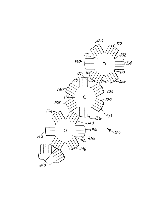
Referring now to Figura 5, there is shown a row
of connected abrasive shéet members generally designated
by reference numeral loO. The illustrated embodiment
includes a plurality of abrasive sheet members 102, 104,
and 106, each of which includes a substrate having a first
major surface 110 and a second opposed major sur~ace (not
shown). At least one major sur~ace has an abrasive layer
thereon, and in an alternate embodiment, both major
surfaces have an abrasive layer thereon.
As with the individual abrasive sheets of the
prior art, abrasive sheet members of the present invention
may be either a coated abrasive or a nonwoven abrasive.
The former includes a backing (e.y. cloth/ paper,
vulcanized fiber, or polymeric film) with abrasive
particles bonded thereto by one or more binder coats of
phenolic resin, urea-formaldehyde resin, acrylate resin,
epoxy resin, aminoplast resin, hyde glue, urethane resin,
polyester resin, or a combination thereof. Nonwoven
abrasives include a substrate, which may be a porous,
fibrous, nonwoven construction and an abrasive comprising
individual abrasive particles on one side of the
substrate. The particles may be made of materials such as
fused aluminum oxide, ceramic aluminum oxide, heated
treated aluminum oxide, silicon carbide, alumina zirconia;
diamond, ceria, cubic boron nitride, garnet, or any other
abrading means known in the art. For example, an abrasive
sheet member sold by Minnesota Mining and Manufacturing
Company of St. Paul, Minnesota under model number 33lD
includes a cloth substrate and aluminum oxide particles
bonded to the substrate using a resin binder may be used
in constructing the present invention.
Abrasive sheet members 102, 104, and 106 each
have a body portion 112, 114, and 116, respectively, and a
plurality of radially extending arm portions 120-154. The
2~7677
g
arm portions are spaced about the perimeter of the body
por~ion at an constant angle ~, as shown in Figure 1,
meaning that the angle between each of the adjacent pairs
of arm portions is substantially constant for that
abrasive sheet member. In the illustrated embodiment, for
example, the six arm portions 132-142 are spaced 60
apart. The desired spacing between arm portions may be
determinad by dividing 360 by the number of arm portions
that each abrasive sheet member has.
Although tha arm portions may be irregularly
spaced about the perimeter of the body portion, such a
configuration may be undesirable because the finished
abrading article may tend to be unbalanced and to abrade
material unevenly. Variations in the angular
configuration of the arm portions are within the scope of
the invention, althou~h the present invention is primarily
directed to abrasive sheet members having regularly
perimetrically spaced arm portions.
The present invention also provides means for
joining each adjacent pair of abrasive sheet members
together in an aligned row, such that the sheet members
may be Z-folded to provide the abrading articl~. As that
term is used herein, "Z-folding" refers to repeated
~olding of a connected row of abrasive sheet members at
foldable junctions between each adjacent pair of abrasive
sheet members, as shown in ~igure 6. A connected row that
has been Z-folded therefore includes a plurality of
connected abrasive sheet members 170, 172, 174, and 176 in
stacked relationship, which may be fastened to an arbor
and used to abrade a workpiece. Z-folding saves time and
expense when compared to manual collection, alignment, and
orientation of individual sheet members, because it
enables the abrasive sheet members of the present
invention to be self-aligned and oriented.
In the preferred embodiment, the joining means
(hareinafter "foldable junctions") are a pair of foldable
junctions between an arm portion of one abrasive sheet
member and two arm portions of an adjacent abrasive sheet
2~87677
--10--
member. As best shown in Figure 5, arm portion 12~ of
abrasive sheet member 102 is connected to arm portion 132
of abrasive sheet member 104 at foldable junction 160, and
to arm portion 142 of abrasive sheet member 104 at
foldable junction 162. In the preferred embodiment, as
illustrated in Figure 5, the foldable junctions are cut
from a sheet material at the same time as the remainder of
the abrasive sheet members, and the abrasive sheet members
therefore remain in a connected row throughout production.
The joining means could also include a pair of foldable
junctions that are bonded (e.g. by pressure sensitive
adhesive, thermal bonding) to each pair of abrasive sheet
members after each sheet member is individually formed.
For each respective pair of abrasive sheet
members, the single arm portion of the first sheet member
is centered between the two arm portions of the second
sheet member. In the preferred embodiment, the foldable
junctions are positioned at the outermost corners of the
arm portions of the first sheet member, and one outermost
corner of each of the two adjacent arm portions of the
second sheet member, as shown in Figures 5, 8, l~, and 12.
This orientation is central to an advantage of the present
invention described above. When the aligned row of
connected abrasive sheet members is Z-folded at the
foldable junctions between each pair of adjacent abrasive
sheet members, the arm portions of each sheet member are
angularly offset by angle ~, which is equal to 1/2 of
angle ~, measured with respect to center point 17, between
the arm portions of the immediately adjacent abrasive
sheet members, as illustrated with respect to the prior
art in Figure 2. Each arm portion thus overlies the space
between the arm portions of the abrasive sheet member
below it and the abrasive sheet member above it, providing
an abrasive article having the desired distribution of arm
portions throughout.
'rhis arrangement of the arm portions is
desirable hecause the abrasive sheet members self-align as
described above when the connected row is Z-folded, due to
20~7677
the relationship between each adjacent pair of abrasive
sheet members. Thus it is not required that a person
sequentially manually position each individual sheet
member with respect to the adjacent sheet members, as was
required of the individual sheet members of the prior art.
In addition, the self-alignment of the arm portions
provides flexible abrading surfaces throughout the
thickness of the abrasive article because there is less
overlap between adjacent abrasive sheet members than would
occur i~ the arm portions were otherwise aligned.
Although several possible embodiments of the
foldable junctions exist, se~eral design considerations
are common to each embodiment. The first involves the size
of the foldable junctions between each adjacent pair of
abrasive sheet members. In order to permit a user to tear
off a predetermined number of abrasive sheet members, the
foldable junctions are preferably easily manually torn,
particularly in response to the application of shear
forces. However, in the preferred embodiment of making the
abrasive article of the present invention, the abrasive
sheet members and the foldable junctions are cut from a
sheet material, and the connected row is wound onto a
take-up roller. Therefore, the foldable junctions must
also be strong enough to ~ithstand the tensile force
applied during the winding portion of the production
process, and unwinding during dispensation. Although the
design of the foldable junctions may vary depending on the
application and the materials that are used, it has been
shown that foldable junctions that tear under a tensile
load of approximately 10 lbs. have utility for some
applications.
A further design consideration relates to the
degree of~protrusion of the foldable junctions after the
connected row of abrasive members has been ~-folded. The
foldable junctions should not project substantially from
the arm portions, because any substantial projection will
tend to abrade a workpiece unevenly when the Z-folded
abrasive article is rotatively urged thereagainst. Thus
~7~7
-12-
the foldable junctions should be designed so as to
minimize any projection by the junctions after the article
has been Z-folded.
Although the embodiment shown in Figure 5 is
that of abrasive sheet members each having six arm
portions, the present invention is not so limited, and has
been shown to have utility with abrasive sheet members
having other geometric configurations~ For example, the
present invention is shown ~ith reference to abrasive
shee~ members having 3 arm portions (shown in a connected
row in Figure ~ and Z-folded in Fi~ure 9), 4 arm portions
(shown in a connected row in Figure 10 and Z-folded in
Figure 11), and 5 arm portions (shown in a connected row
in Figure 12 and Z-folded in Figure 13). An appropriately
designed abrasive sheet member having 2 arm portions or
more ihan 6 arm portions is also contemplated~ and
therefore it is preferred that the abrasive sheet members
have between 2 and 30 arm portions each, and most
preferred that the abrasive sheet members have between 3
and 10 arm portions. However, the present invention
expressly encompasses geometric configurations including
more arm portions than the embodiments specifically
described herein. The overall diameter of the abrasive
sheet members may, for example, range from 1 cm. to 100
cm., and is usually between 5 cm. and 20 cm.
The present invention also includes within its
scope a connected row of abrasive sheet members wherein
adjacent sheet members have different numbers of arm
portions. For example, alternating abrasive sheet members
having 4 arm portions with abrasive sheet m~mbers having 8
arm portions is also possible using the features of the
present invention. It should be noted that abrasive sheet
members having larger numbers of arm portions tend to
require that the arm portions be thinner, and therefore
less durable under the stresses applied during abrasion.
Durability is important because greater durability allows
an operator to work for longer periods of time, and thus
abrasive sheet members having the number of arm portions
2~7677
-13-
listed above, because the arm portions tend to be wider,
are desired. Furthermore, abrasive sheet members having
very few arm portions, such as the three armed abrasive
sheet members shown in Figures 8 and 9, tend to have more
pronounced corners when the row is Z-folded, as indicated
by reference numeral 180 in Figure 9. These corner
portions may abrade a workpiece unevenly, which mitigates
in favor of abrasive sheet members having greater numbers
of arm portions. The optimum number of arm portions for a
given application must be determined based on the material
to be abraded, the profile of the workpiece, and other
considerations. Alternately, the ends of Pach arm portion
may be rounded slightly about a constant radius, as shown
in Figures 1 and 2 with respect to the prior art, which
may help to eliminate the potential overcutting due to the
pronounced corners described above.
Formed in the body portions of each of the
abrasive sheet members is at least one aperture, which
apertures are substantially in register when the connected
row of abrasive sheet members is Z-folded. The preferred
embodiment, as shown in Figure 5, includes one aperture
formed at the center point of each abrasive sheet member.
Also contemplated are multiple apertures formed in the
body portions of each of the a~rasive sheet members, as
shown in Figures 8 and 9 (3 apertures regularly spaced at
a constant distance from the center), Figures 10 and 11 (2
apertures; one in the center, and one spaced from the
center), and Figures 12 and 13 (2 apertures, each spaced
from the center~, so long as each aperture of aach
abrasive sheet member is substantially in register with
the corresponding apertures of the other sheet members
when the sheet members are Z-folded. Furthermore, the
aperture or apertures may be hexagonal, triangular, or
otherwise shaped to fit a shaft or pin inserted
therethrou~h to retain the abrasive article.
The importance of the apertures being
substantially in register lies in part in the method used
to retain a group of Z-folded abrasive sheet members. An
2V87~7~
-14-
abrasive article according to the present inven~ion may
include very few sheet members (e.a. 2) or very many (e.q.
1000), but most preferahly contains between 10 and 50
abrasive sheet member~. ~fter a predeterminsd number of
abrasive sheet members have been separated from a supply
of connected abrasive sheet members and Z-folded to form
the abrasive article, an arbor and a retainer
cooperatively sngage through the apertures to retain the
abrasive article with respect to the arbor. The arbor may
then be attached to a source of rotary power to rotate th~
article, which may be urged against a workpiece to abrade
the workpiece. Because the apertures of the abrasive sheet
members are self-aligned when the row is Z-folded, the
step of manually aligning the apertures of numerous
individual sheet members, as taught by the prior art, is
reduced or eliminated.
In the preferred embodiment, as shown in Figure
7, the arbor 190 includes a shaft portion 192 and a
backing m~mber 194, including a threaded chamber 195
adapted for receipt of a cooperative threaded male
retainer 198. Retainer 198 and arbor cooperate through the
aligned apertures of the retained abrasive article 100' to
retain the article with respect to shaft portion 192.
Shaft portion 192 is adapted to be held by a source of
rotar~ power, and transmits the rotary power to abrasive
article 100', which may then be urged against a workpiece
to abrade the workpiece. An exemplary arbor and retainer
for use with the abrasive article of the present invention
is sold by the 3~ Company of St. Paul, Minnesota under the
trademark Roloc Plus~. Alternate embodiments of arbor 190
and retainer 198 include an arbor with a portion that
passes through the aligned apertures, a single piece
arbor/retainer wherein arbor/retainer is passed through
the aligned apertures until the abrasive article is
retained within an annular groove near the base of the
arbor/retainer, and the like.
The present invention may also be used in
conjunction with a backing pad, in order to provide extra
2~87S~7
-15-
support to the abrasive article. If a backing pad is used,
the backing pad is preferably smaller than the diameter of
the abrasive article, and is preferably constructed of
rubber, metal, plastic, or reinforced plastics. If rubber
is used, it should have a hardness between 20 and 95 Shore
A durometer, preferably between 70 and 75 Shore A
durometer.
In order to reduce the possibility of edge
cutting and to permit the abrasive article to be used to
abrade contoured surfaces, the preferred embodiment of the
present invention includes arm portions that are slashed.
The preferred embodiment is shown in Figure 5, wherein
each arm portion of each abrasive sheet member includes a
plurality of spaced parallel cuts through the material
comprising the arm portions, thereby adding flexibility to
the outer edges of the arm portions. The slashed edges
could also include cuts in a radial direction, non-linear
cuts or other similar variations.
Also provided is a method of making an abrasive
article according to the present invention. Generally, the
method involves providing a continuous shest of material
having an abrasive on one surface to a cutting apparatus.
The apparatus cuts an aligned row of connected abrasive
members from the sheet of material, and collects the row
of connected abrasive sheet members for shipment or
packaging. The row of connected abrasive sheet members may
also be divided into smaller units (~g~ 500 sheet
members) and packaged for convenient dispensation and use.
As shown in Figure 14, a continuous supply of
sheet material 200 is provided having first and second
major surfaces 202 and 204, respectively, at least one of
which comprises an abrasive layer. The sheet material and
abrasive layer (or layers, if each major surface is coated
with an abrasive) are the same as those described above
with reference to the abrasive sheet members. Sheet
material 200 is supplied to a cutting apparatus 210, which
includes die cutter 212, support frame 214, and power
source 216. Sheet material 200 may be sized to permit a
20~7~77
-16-
single, continuous row of connected abrasive sheet
members, or may be sized to permit the production of
multiple rows of connected abrasive sheet members, as
indicated at 220 ~he dimensions of die cutter 212 may be
- 5 designed to match the width of the sheet material.
Die cutter 212 is shown as a continuous rotary
die cutter, meaning that the die will cut the connected
abrasive sheet members from the sheet material
continuously, as opposed to cutting the connected abrasive
sheet members in a batch cutting operation. Although the
connected, aligned row of abrasive sheet members could be
die cut in long rows te-q- 40 sheet members per batch),
continuous rotary die cutting is the preferred embodiment
for manufacturing purposes. In the preferred embodiment
1~ the die cuts the abrasive sheet members and the foldable
junctions simultaneously, as well as the aperture or
apertures in the body portions of each of the abrasive
sheet members. The die may also be adapted to form cuts in
the arm portions to produce the desired slashed edges.
After the connected abrasive sheet members 222
are cut from the sheat material 200, weed 224 is separated
from the sheet members and discarded. The connected
a~rasive sheet members are then rotatively collected on
roller 226 for shipping and/or dispensation. As noted
~5 previously, the required design strength of the foldable
junctions depends in part on the force with which roller
226 withdraws the connected abrasive sheet members from
cutting apparatus 210.
As described briefly above, large rolls of
connected abrasive sheet members could easily be divided
into several smaller rolls, to aid in packaging,
dispensation, and use. The connected abrasive sheet
members of the present invention may be dispensed for use
from a container having a continuous roll of connected
abrasive sheet members therein. The connected sheet
members may be manually torn from the roll, or
alternately, means for severing a predetermined number of
the sheet members from the roll could be provided. An
2~87677
-17-
appaxatus that may be useful in this regard is disclosed
in U.S. Patent No. 3,849,949 (Steinhauser et al.), the
disclosure of which is hereby incorporated by reference.
Alternatively, a roll of the connected sheet members could
be rotatively mounted, and a predetermined number of sheet
members torn off for Z-folding and use.
The present invention has now been described
with reference to several embodiments thereof. It will be
apparent to those skilled in the art that many changes can
be made in the embodiments described without departing
from the scope of the invention. Thus, the scope of the
present invention should not be limited to the structures
described herein, but only by structures described by the
language of the claims and the equivalents of those
structures.
82841011P~SPC