Note: Descriptions are shown in the official language in which they were submitted.
~087990
A PROCESS AND APPARATUS FOR FORMIN~ SELVAGE OF sEpARAsLE
FASTENER
BACKGROUND OF THE INVENTION
Field of the invention
The present invention relates to a process and
apparatus for forming sel~ages that constitutes a part to be
stitched together with clothin~, on the surface of a
separable fastener.
Separable fasteners comprise a substitute and, provided
by weaving or knitting on the surface thereof, loop-like or
hook-like fastening elements and are used for engaging two
ltems with each other, in place of buttons and the like.
FIGURE 3 shows an example of such separable fasteners.
In FIGURE 3 (a), a separable fastener 1 isr for exam-
ple, a female separable fastener and comprises a substrate
11 and, projecting on the surface 1a thereof, a multiplicity
of loop-like fastening elements 12. On the back surface lb
of the separable fastener 1/ there is providad a coating
layer (not shown) to prevent the fastening elements 12 from
dropping off from the substrate 11. These substrate 11,
fastening elements 12 and coating layer generally comprise
Z5 thermoplastic resins such as polyester and polyurethane.
The separable fastenex 1 is provided, in the longitudinal
direction A, with selvages that constitute a joining part to
be stitched with a wear or like items. The separable
-1-
20879'i~
fastener 1 is obtained by slitting a wider one as shown inFIGURE 3 (b) along its length A and at the middle of flat
parts 14, which parts form, aftar the slitting, the sel-
vages. A known process for forming the selvage 13 comprises
slitting a wide separable fastener 1 into a plurality of
narrow shapes and then, with circular cutters 50 provided on
both sides of the narrow separable fastener 1B, forming
selvages 13 on both edges of the separable fastener 1B, as
shown in FIGURE 4 (see for example ~apanese Patent Applica-
tion Laid-open No. 46114/1972). Also known is a process
which comprises, as shown in FIGURE 5, contacting the knives
52 of an electric hair clipper 51 on the surface of a wide
separable fastener lA to remove the fastening elements and
then slitting with a cutter 53 the separable fastener 1A
into narrow separable fasteners 1B (see for example Japanese
Patent Application Laid-open No. 14438/1975).
The substrate 11 of separable fasteners 1A and 1B
generally have, however, wavy-pattern projections or an
irregular surface. As a result, with the above known
processes, there sometimes remains root part of some of
fastening elements, so that the selvage 13 cannot always be
sufficiently flattened.
Further with separable fasteners having loop-like
fastening elements, i.e. female separable fasteners, the
flexible fastening elements renders it difficult to cut the
elements at the roots. In this case either, a sufficiently
fla-t selvage 13 cannot be formed.
.. . .
'- . , ' " ' . ` `, ' ' , . . ~ .
2087990
Japanese Patent Application Laid open No. 14438/1975
discloses, to solve the above problem, a process which
comprises removing fastening elements 12 with an electric
hair clipper 51 and, thereafter, flattening the roughened
surface, where the elements have been removed, by electric
fusion. This process, however, requires an additional step
-for flattening, which is uneconomical.
Japanese Patent Application Laid-open No. 194802/1987
discloses a process which comprises contacting a rotating
grinding wheel 54 onto the surface 1a of a separable
fastener 1A, as shown in FIGUR3 6, to remove the fastening
elements at the roots. This process, however, causes
clogging on the surface of the grinding wheel 54 due to fine
chips of the removed fastening elements 12, although most of
the chips are removed through a suction duct 55. Then, a
continuous operation becomes difficult to maintain.
Accordingly, an object of the present invention is to
solve the above problems and provide a process and apparatus
that can form sufficiently flat selvages 13 on the surface
of separable fasteners continuously.
Thus, the present invention provides a process for
forming selvages, which comprises, while conveying a
separable fastener in the longitudinal direction, internally
heating the separable fastener along the conveying path A
and, at the same time, fusing the fastening elements 12 with
the substrate 1'I by pressing the fastening elements 12 onto
the substrate 1l to form flat parts 14 that will constitute
-3-
20~7~90
selvages 13, with a plurality of press rolls 4 provided in a
spaced relationship with each other in the widthwi~e direc-
tion of the separable fastener (hereinafter this process is
referred to as "flat part-forming process").
On this occasion, there may be employed a process which
comprises, at the same time with or after the above
formation of flat parts, slitting the middle part of each of
the flat parts along the conveying path, thereby forming
selvages along the cut edges (hereinafter this process is
referred to as "slitting process").
The present invention also provides an apparatus for
forming selvages, which comprises:
a conveying device for conveying a separable fastener
in the longitudinal direction,
an internal heating device, provided near the conveying
path of the separable fastener, for heating the separable
fastener from its inside and along the conveying path A,
a support that contacts the back surface of the heated
separable fastener and
a press rolI that contacts the surface of the separable
fastener and presses the separable fastener between the
above support and fuses the f.astening elements onto the
: substrate, to form on the separable fastener a flat part 14
that will constitute selvages 13.
BRXEF DESCRIPTION OF THE DRAWINGS
A more complete appreciation of the invention and many
.. . . . . .
20~7990
of the attendant advantages thereof will be readily obtained
as the same become better understood by reference to the
following detailed description when considered in connection
with the accompanying drawings, wherein:
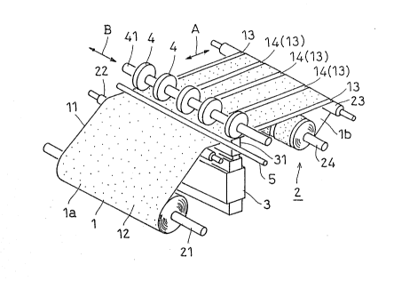
FIGURE 1 is a perspective view showing an example of
the apparatus for forming selvages of separable faster
according to the present invention;
FIGURE 2 is a side view showing the essential part of
the apparatus for forming selvages according to the present
invention;
FI~,URE 3 .is a perspective view showing an example of
separable fastener;
FIGURE 4 is a plan showing a first example of
conventional apparatuses;
FIGURE 5 is a side view showing a second example of
conventional apparatuses; and
FIGURE 6 is a cross-sectional view showing a third
example of conventional apparatuses.
DETAILED DESCRIPTION OF PREFERRED EMBODIMENTS
In FIGURE 1, a separable fastener 1 comprising a
substrate 11 and, on its surface 1a, fastening elements 12
has been wound on an unwinding roll 21. The separable
fastener 1 is guided through guide rolls 22 and 23 and taken
up on a winding roll 24. These rolls 21 through 24
constitute the conveying device 2 c~ntained in the apparatus
oE the present invention. The conveying device 2 is to
'''i:' .'~. , ''' , , ''`'~ ~,
:~' .: ' ' ''' :. ~ ` :.
:~ ~.: : ... : ~ . - : , : . '' .. :
2~87990
unwind the separable fastener 1 and convey it in the
longitudinal direction A.
At a position in the conveying path for the separable
fastener 1, an internal heating device 3 is provided in such
a condition as to contact the back surface 1b of the sepa-
rahle fastener 1. The internal heating devic0 3 comprises,
for example an ultrasonic oscillator or high-frequency
oscillator and oscillates supersonic wave or high-frequency
oscillation from the horn 31 (support) at the top and
internally heats the separ.able fastener I in the conveying
direction A to elevate its temperature. In this embodiment,
the top surface of the horn 31 contacts, as shown in FIGURE
2, with the back surface 1b of the separable fastener 1.
The horn 31 may be made of titanium alloy capable of forming
highly flat selvages 13~ It is advisable to cover with
- Teflon the surf.ace of the horn 31 that contacts the back
surface 1b of the separable fastener 1.
On the surface 1a of the separable fastener 1 and oppo-
site to the position of the horn 31, a plurali.ty of pressrolls 4 that contact with the surface 1a of the separable
fastener 1. The press rolls 4 press the .separable fastener
1 against the horn 31 and fuse or weld the heated fastening
elements 12 onto the substrate 11, to form, as shown in FI-
GURE 1, flat parts 14 on the separable fastener 1 that willform selvages 13 later on. The press rolls 4 are mounted~
- in a plural number and in a spaced relationship with each
other in the widthwise direction B of the separaole fastener
', 'i ' ' ' ', "'.'' '';~' " ~ '', ' ''' " '. ' ', ' ' ' '':, . ' . ' .
2~87990
1, on a rotating shaft 41 driven by a motor. The roll width
of the press rolls ~ is nearly the same as the width of the
flat parts 14 to be formed, and the pitch of the press rolls
4 is the same as the pitch of the flat parts 14. While the
press rolls 4 are made of stainless steel, their surface
that contacts the surface 1a of the separable fastener may
be covered with Teflon to increase releasability.
At a position in the downstream side of the press rolls
4, a cooling pipe 5 is mounted in the widthwise direction B
of the separable fastener. The cooling pipe 5 is, as shown
in FIGU~E 2, provided in the above widthwise direction B
with a multiplicity (for instance at least the number of the
flat parts 14 to be formed of the separable fastener) of
nozzles 5a (for instance, circular diffusers having a dia-
meter of 5 to 10 mm) that blow out air C cooled by adiabatic
expansion of compressed air or like methods (for instance,
at a temperature of -20 to 0C and at a speed of 3 to lO
m/sec~. It is desirable to cool locally the flat parts and
their vicinity just after heating and pressing, and hence it
is preferable to provide the nozzles 5a for every flat part
14, i.e. for every press roll 4. The positions of the
nozzles 5a may, for cooling devices that comprise a cooling
pipe 5 and, connected thereto through flexible tubes or
movable pipes, the nozzles 5a, be changed conforming to the
intended positions of the flat parts 14 or depending on the
type of the separable fastener.
The process for forming selvages of the present
. .
20~79go
invention is described next.
The separable fastener 1 is, while being conveyed in
the conveying direction A from an unwind roll 21 to take-up
roll 24 through the conveying devic~ 2 shown in FIGURE 1,
internally heated with an internal heating device 3. At the
.same time with the separable fastener 1 being heated to an
elevated temperature, the fastening elements 12 are pressed
with press rolls 4 against the substrate 11, thereby
integrally fusing with the substrate 11. As a result, flat
parts 14 that will become selvages 13 are formed on the
surface 1a of the separable fastener 1.
It is desirable that the clearance between the press
rolls 4 and the horn 31 is in a range of from (the thickness
of the substrate 11 before pressing + 0.2 mm) to (the
thickness of the substrate 11 before pressing - 0.2 mm).
i .
This range assures good fusibility of the fastening elements
with substrate 11, thereby providing flat parts 14 having
good smooth surface. The clearance is more preferably in a
range of from (the thickness of the substrate 11 before
pressing + 0.2 mm) to (the thickness of the substrate 11
before pressing - 0.1 mm).
There may be provided, together with the above device
for forming flat parts and in a suitable position, a cutter,
high frequency fusing cutter or ultrasonic fusing cutter.
By using this cutter, the middle of each of the flat parts
14 is, at the same time with or after their formation, slit
in the conveying direction A, whereby narrow sepaxable
2~7~0
fasteners 1B having selvages 13 on both sides thereof are
produced, as shown in FIGURE 3(a).
In the above embodiment, the fastening elements 12 are
fused with the substrate 11 in such a manner, as shown in
FIGURE 2, that the heated separable fastener 1 is flattened
between the horn 31 and the press rolls 4. This process
therefore is capable of forming sufficiently flat selvages
13 by pushing down fastening elements 12, even when the
substrate has wavy-pattern projections or irregular surface
or when the fastening elements 12 are flexible loop-like
elements~
Since the process of the invention comprises fusing the
fastening elements 12 with the substrate 11, there occurs no
troubles such as clogging of grinding wheel with chips and
it is possible to carry out continuous operation.
The process provides another advantage of causing no
loosening of fastening elements 12 upon stitching, since,
then, the selvage including a coating layer on its back
surface lb has once fused.
One may consider heating the separable fastener 1 by
external heating, not by internal heating. External
heating, howeverf has the drawbacks such as temperature ele-
vation of fastening elements 12 alone that has large surface
area and small heat capacity. On the other hand, the
present invention employs internal heating, which realizes
integral and comparatively uniform temperature elevation
free from the above drawback.
, . ~
2 0 ~ 0
After the above press1ng and fusing steps, there may
occur the following troubles.
The fastening elements 12 may, because of its small
heat capacity, elevate its temperature to an extent unneces-
sary or break upon.contact with press rolls 4 at an elevatedtemperature. Wavy-pattern projections or warping may
generate in the flat parts 14 or wide separable fastener 1
(1A) itself due to variation in the conveying speed among a
plurality of portions (that will, after slitting, become
narrow separable fasteners.1B) containing rows of fas~ening
elements and sandwiched by adjacent flat parts 14. This is
because that the wide separable fastener 1 (1A) is under
tension in the conveyin-g direction A, which is not always
uniform in the widthwise direction B; and that, when the
wide separable fastener 1 is heated and pressed bet~,e~.-n the
press rolls 4 and horn 31, the flattened parts 14 of the
substrate 11 will soften. Such wavy pattern or warping
forms more readily, the longer the flat parts 14 being in a
softened condition. This phenomena may hinder the formation
of narrow separable fasteners 1B with selvages having neat
appearance.
To solve the above problem, this embodiment of the
present invention provides blow-out nozzles 5a that blow
cool air C against the flat parts 14 just after contact of
the press rolls 4 and the separable fastener 1. The cooling
prevents the fastening elements 12 from being damaged by
heat and also the flat parts 14 from genarating the above
-~o-
.. . . .
20~79~0
wavy pattern or warping upon continuous ~ormation of
selvages 13.
While in the above embodiment the separable fastener 1
is pressed at the same time with internal heating, in the
present invention the separable fastener may be pressed just
after internal heating.
The process of the present invention is also applicable
to male separable fasteners having hook-like or mushroom
type fastening elements. For male separable fasteners
having hook-like fastening elements comprising synthetic
monofilament, in the present invention, the hook formation
process can be combined with the above flat part-forming
process and slitting process, whereby narrow separable
(male) fasteners lB having selvages on both sides thereof
can be continuously produced.
In the above continuous process, while the hook forma-
tion process can be provided before the above flat part-
forming process, it is preferably provided after the flat
part-forming process. The superiority of the latter
combination is because the uniformity of the pushing down
directions of fastening elements differs depending cn the
shape of the fastening elements and that loop-like fastening
elements (precursor of hooks before cutting) are pushed down
more uniformly by heat pressing than hook-like fastening
elements (after cutting of loops), which have only one leg,
so that the hoo]c formation after flat part-forming process
can give selvages having more uniform appearance. The
20~7~90
. .
latter combination further has the advantage of assuring
good smoothness of the flat parts. This is because that the
fastening elements to be pushed clown and flattened by heat
pressing are of loop shape and hence fuslon of onl~ part of
each loop to the substrate 11 fixes the entire loop, laying
flat, on the substrate surface. On the other hand, the
above former combination must, in order to complete pushing
down, fuse 2 pieces of monofllament projections remaining
after cutting off of part of the side of a loop comprising a
monofilament.
The hook formation process may be, after flat part-
forming process, provided either before or after the
slitting process, but it is preferable to provide it before
slitting, which assures integral, compact provision of the
loop-cutting device.
In the above hook formation process, loops comprising
monofilament are, as the separable fastener is conveyed in
the direction A, permitted to pass through needle-like sta-
Z0 tionary knives provided in the widthwise direction B of theseparable fastener in a number corresponding to the number
of the rows of the loops and in positions each contacting
the point on one side of a loop to be cut, to form hooks.
In this embodiment, the above needle-like stationary knife
is employed as cutting means for cutting loops comprising
monofilament into hooks, because this system realizes high
conveying speed, i.e. high productivity, utilizing the
feature of the present invention capable of continuously
-12-
2087~90
forming a plurality of narrow separable fasteners hav.ing
smooth selvages on both sides thereof. Other processes may,
however, also be used, such as one using a hair clipper (see
~or example Japanese Patent Publication No. 13511/1967) and
one comprising combination of a vibrating knife emitting
ultrasonic fine vibration and a stationary knife (see for
example Japanese Patent Publication No. 12603/1982).
- According to the present lnvention, separable fasteners
with various sizes can be produced by changing the mounting
pitch and/or roll width of the press rolls 4 shown in FIGURE
1.
It is needless to sa~, in the present invention, that
the temperature of the separable fastener 1 should be
maintained within a range that assures fusibility of the
materials of the separable fastener and no melt down of the
substrate l1 to rigid shape.
Obviously, numerous modifications and variations of the
present invention are possible in light of the above
teachings. It is therefore to be understood that within the
scope of the appended claims, the invention ma~ be practiced
otherwise than as specifically described herein.
-13-