Note: Descriptions are shown in the official language in which they were submitted.
20~7~96
APPARATUS FOP~ COLD DRYING OF GAS
The invention relates to apparatus for the cold drying
of gas, in particular of compressed air, including a
heat exchange means and a drying means in an integral
unit, through which a cold-carrying medium flows to
cool the gas to such a temperature that the moisture
present in the gas is precipitated as a condensate.
Generally speaking moisture, as a rule water vapour, is
contained in gases under atmospheric conditions, but
there may also be quantities of other substances which
are volatile at elevated temperatures. This applies in
particular to gases which are under pressure.
For drying gases, in particular compressed air, above
0C cold dryers are employed and below a temperature of
0C and below the pressure dew point adsorption or
absorption dryers are employed.
In the cooling or cold condensing of gases such as air
this takes place - in so far as drying is necessary -
in a separate step, after which it is then cooled down
to the desired value. Accordingly two independent and
separate units are required.
Accordingly, the cold drying of gases results in
problems both from the energy point of view as well as
from the structural aspect.
Apparatus having favourable energy consumption for the
cold drying of gases is known from ~E-A-39 41 713.
This employs two heat exchangers, the main heat
exchanger employed for the cooling having a pre-heat
exchanger connected ahead of it, in which the incoming
gas is cooled by the already dried emerging gas. In
2087996
order to prevent icing-up, which can lead to failure of
the equipment, heat transfer is restricted so that
undisturbed operation is achieved. This requires
special measures to be taken in cons-truction, and a
substantial outlay in control equipment.
It is the aim of the invention to provide apparatus of
simple construction and effective operation for the
cold drying of gases, in which the danger of icing-up
.is eliminated.
According to the invention, apparatus for the cold
drying or cold condensing of gas comprises an integral
heat exchange means and drying means, said heat
exchange means and drying means having an inlet for
said gas, said inlet leading to first passage means
through which said gas flows to be cooled and dried and
an outlet for said cooled and dried gas, and second
passage means for flow of a cold-carrying medium from a
supply to cool and dry said gas, such that moisture
contained in said gas condenses out, forms frost,
freezes out and/or liquefies, said apparatus
incorporating at least one discharge pipe for draining
said liquid condensate, said frosted condensate, said
frozen condensate and/or said liquid separately from
said gas outlet.
In the invention cooling and drying are now combined,
even in the case of cooling below 0C. The liquid
condensate is removed as it occurs, through a discharge~
pipe mounted at a suitable point, thus avoiding an
excess of moisture which could lead to the apparatus
icing up in the case of cooling to low temperatures.
Preferably, the apparatus has at least two heat
exchange zones, of which at least one can be cooled to
2~879~
a temperature greater than 0C. A discharge pipe for
condensate can then be provided at least at the end of
this cooling zone, and also in its initial section
where experience has shown that a large part of the
liquid condensate occurs.
Alternatively, the apparatus may have at least two heat
exchange zones, of which at least one can be cooled to
a temperature below 0C. Here the freezing out takes
place in the form of coarse deposits of frost on
specially shaped surfaces of cooling surfaces. Also
there can be provided in this zone a discharge pipe for
condensate in order to separate out liquid components.
An apparatus for cooling in stages can be constructed,
in which each of the heat exchange zones is provided
with a separate supply of cold-carrying medium. In
this way the individual heat exchange zones can be
brought to different temperatures independently of one
another.
The cold-carrying medium can be in the form of a cold
medium coming from refrigerating equipment, to effect a
regulation of the temperature, in particular above the
pressure of the cold medium. E~ternally regulated
cold-carrying media such as brine or deep-cooled
liquids may also be used. In any case one can operate
with several different temperature levels, which is
particularly important when there is also pre-cooling
above 0C. In this case it is not necessary for there`
to be interchange between liquid and solid phases in
the condition of the condensate.
In a further embodiment, the second passage means is
provided around the first passage means, the gas
2087~96
emerging from the first passage means being fed back
into the second passage means, the heat exchange zones
being followed by a device for relieving the pressure
of the gas.
The invention will be further explained by way of
example in conjunction with the accompanying drawings,
in which:
ig. 1 shows a first embodiment by way of example of
apparatus according to the present invention
in which a continuous heat exchanger is
provided with a drying function for
temperatures both higher and also lower than
OC,
ig. 2 shows a second embodiment of apparatus
according to the present invention in which a
first heat exchange zone is provided with a
drying function for temperatures greater than
0C and a second heat exchange zone, separate
from the first, is provided with a drying
function for temperatures lower than 0C.
ig. 3 shows a third embodiment of apparatus
according to the present invention in which a
first and a second heat exchange zone is
provided with a drying function for
temperatures greater than 0C and a third and
a fouxth heat exchange zone with a drying
function for temperatures below 0C, the
zones each being separate,
ig. 4 shows a fourth embodiment of apparatus
according to the present invention, in which
a continuous hea~ exchanger is provided with
2~7~
a drying function as well as with a cooling
counter-current flow produced by a reduction
in pressure,
ig. 5 shows a fifth embodiment of apparatus
according to the present invention which is
of similar construction to the apparatus of
Fig. 4 but in which the gas flow is
de-pressurised under control to regulate the
fall in gas temperature.
ig. 6 shows a sixth embodiment of apparatus
according to the present invention, in which
two separate heat exchange zones of the kind
shown in Fig. 4 and ~ and Fig. 2 and 3 are
connected together, and
ig. 7. shows a seven~h embodiment of apparatus
according to the present invention, in which
two mutually separate heat exchange zones of
the kind shown in Fig. 2 are provided side by
side in an upstanding arrangement.
.
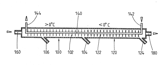
Fig. 1 shows a first embodiment by way o~ example
according to which a continuous heat exchanyer lO0~ 120
is provided in the form of a longitudinally extending
cylindrical tube which has a pipe 140 arranged
centrally within it and extending over substantially
its entire length, a cold-carrying medium being
conducted through the pipe. At one end of the heat-
exchanger 100, 120 there is a gas inlet 160 through
which the gas to be dried is introduced into the heat
exchanger 100, 120 and the gas outlet 180 for the dried
gas is provided at the other end.
.
2~87~g~
The heat exchanger is divided into two adjacent zones,
and in the heat exchange zone 100 adjacent to the gas
inlet 160 a temperature higher than 0C prevails,
whereas in the zone nearer the gas outlet 180 the
temperature is less than 0C, the temperatures being
reduced respectively by the continuous cold-carrying
medium flowing through the pipe 140. In this
arrangement an inlet 142 for the cold-carrying medium
is led through the wall of the heat exchanger in the
neighbourhood of the gas outlet 180 and an outlet 144
for the cold-carrying medium is in the neighbourhood of
the gas inlet 160, the medium being progressively
warmed up on its path through the pipe 140 and through
the heat exchange zones 100, 120.
In this arrangement the degree of heating can be
controlled for example by its velocity of flow or by
its pressure and/or the quantity flowing through.
Cooling surfaces 102, 122 are arranged on the outside
of the pipe 140, shaped specially for each heat
exchange zone 100, 120 so that they can fulfil their
cooling and drying function in an optimum manner.
Thus, the cooling surfaces 122 in the heat exchange
zone 120 which is operated at temperatures below 0C
are arranged so that they favour the deposition of
frost or ice. On the underside of the heat exchanger
discharge pipes 104, 106, 124 are led out and in fact
in the heat exchange region 100 there is respectively a
discharge pipe 104 for liquid condensate in the
neighbourhood of the transition point to the heat
exchange zone 120 and a discharge pipe 106 for liquid
condensate about one third of the way along the cooling
stretch, that is to say, lying nearer the ~as inlet
160, and in the heat exchange zone 120 at the end of
the cooling stretch, that is to say about in the region
2~7~9~
of the inlet 142 for the cold-carrying medium, there is
a discharge pipe 124 for so-called ice-condensate or
liquefied gas.
Gas introduced into the apparatus through the gas inlet
160 is cooled by the action of the cold-carrying
medium, and at first a temperature greater than 0C is
maintained so that condensate precipitates out in the
liquid phase and is conducted away through the
discharge pipe 106 and also the discharge pipe 104.
Using this arrangement for discharying liquid
condensate the formation of massive ice deposits in the
heat exchange zone 120 is obviated.
The cooled and partially dried gas then passes into the
heat exchange zone 120, of which the cooling surfaces
122 have an increased surface area compared to those in
the heat exchange zone 100 and favour the precipitation
of the condensate as fine ice which adheres to the
cooling surfaces 122.
To free the deposits of frost or fine ice the gas flow
is advantageously interrupted and the deposit is
removed by impact or by thawing. In cases where the
gas flow is not to be interrupted, one can switch over
to another heat exchanger or another apparatus of the
same construction so that alternate operation can be
undertaken.
In Fig. 2 is illustrated a second embodiment by way of
example, in which a first heat exchange zone 200 with a
drying function is provided for temperatures greater
than 0C and a separate second heat exchange zone 220
with a drying function is provided for temperatures
below 0C. The two heat e~change zones 200, 220, which
form a longitudinally extending unit, communicate
2~799~
through a connecting pipe 270 which is connected to two
adjacent opposing faces of the heat exchange zones 200,
220, which are formed as substantially closed tubes,
and in which prevails a temperature of about 0C or
slightly above. At the other end face of the heat
exchange zone 200 there is an inlet 260 through which
the gas to be dried is introduced into the heat
exchange zone 200. At the other end face of the heat
exchange 220 there is the gas outlet 280 for the dried
and cooled gas.
For each heat exchange zone 200, 220 there is a
separate pipe 240, 250 for cold-carrying medium,
arranged substantially centrally over the entire length
of the respective heat exchange zone 200, 220, the pipe
240, 250 being supplied with a cold-carrying medium in
such a way that the temperature profile described above
is maintained. Again each pipe carries cooling
surfaces 202, 222 which are shaped according to the
specific cooling requirement. Inlet 252, 242, and
outlet 254, 244 are arranged as in the embodiment
described in Fig. 1, but now in each of the heat
exchange zones 200, 220.
Furthermore in each of the heat exchange zones 200, 220
there is provided on the underside a discharge pipe
204, 224 for condensate, each at the end of the cooling
stretch of the corresponding zone. In this arrangement
the discharge pipe 204 serves for discharging liquid
condensate precipitated in the heat exchange zone 200
before the gas enters the connecting pipe 270, which is
narrower than the heat exchange æones 200, 2~0. The
deposition in the form of ice condensate or liquified
gas again takes place in the lower temperature heat
exchange zone 220.
2~7~9~
The cooling and drying can also take place in several
temperature stages. Thus, Fig. 3 shows a third
embodiment in which a first and a second heat exchange
zone 300, 310 are provided for the drying function for
temperatures greater than 0C and a third and a fourth
heat exchange zone 320, 330 with a drying function for
temperatures below 0C, the zones each being separate
so that a different temperature can be set in each Gf
them.
The gas which is to be dried and cooled is introduced
through a gas inlet 360 at the end face of the first
heat exchange zone 300, and there it is cooled in a
first stage, the condensate which is precipitated in
liquid form being conducted away through the discharge
pipe 304; it then passes through a connecting pipe 372
of reduced cross-section into the second heat exchange
zone 310 where a lower temperature prevails than in the
first zone, but the temperature still lies a~ove 0C.
Again condensate can be removed from the heat exchange
zone through a discharge pipe 314. The gas then passes
through a connecting pipe 370 corresponding to the
connecting pipe 270 of Fig. 2 into the third heat
exchange zone 320 in which the temperature is now set
lower than 0C, and from there through a connecting
pipe 374 into the fourth heat exchange zone 330 where
the lowest temperature in the entire apparatus
prevails, until finally it is removed through the gas
outlet 380. The heat exchange zones 320 and 330 are
each likewise also provided with a discharge pipe 324
and 334 respectively at the end of the cooling stretch
in order to allow the precipitated condensate to escape.
Each heat exchange zone 300, 310, 320, 330 has a pipe
358, 350, 348, 340 passing through it, with an inlet
356, 352, 346, 342 for the cold-carrying medium at the
2~799~
low-temperature end of the respective heat exchange
zone and an outlet 362, 354, 376, 344 leading out at
the high-temperature end, and fed in a manner known in
itself from a refrigerating apparatus. Again cooling
surfaces 302, 312, 322, 332 of an appropriate form are
arranged on the pipes 358, 350, 348, 340. In this
arrangement they are arranged at a closer mutual
spacing in the first heat exchange zone 300 than in the
second.
The heat exchange zones can have different lengths
where this appears to be necessary for an optimum
cooling function. For example the fourth heat exchange
zone 330 is made substantially shorter than the
remainder.
In the embodiments described so far the cooling takes
place through a cold-carrying medium such as a cooling
medium from one or more refrigerating e~uipments.
However, i~ is also possible to make use of a
counter-current cooling layout using the cooled gas, as
will now be described in conjunction with Fig. 4.
According to Fig. 4, cooling surfaces 402, 422, of the
desired form are arranged on the inner walls in a heat
exchanger 400, 420 having two heat exchange zones which
are in the form o~ a cylindrical pipe. In this
arrangement the cooling surfaces 402 in the heat
exchange zone 400 correspond to those for temperatures
above 0C and the cooling surfaces 422 in the heat
exchange zone 420 those for temperatures below 0C.
The heat exchanger 400, 420 is surrounded over
substantially its entire length by a cooling tube 472
which communicates through a pipe loop 470 with the
heat exchanger 400, 420 and it has a gas outle~ 480 at
208~9~
its other end. Gas introduced through a gas inlet 460
into the heat exchanger 400, 420 is thus fed back and
employed as a cold-carrying medium. The further
cooling of the gas necessary for this takes place
within the pipe loop 470 in which, downstream of a
discharge pipe 424 for condensate, there is provided a
restriction 426, for example in the form of a venturi
nozzle The gas expands downstream of the restriction
426 and thereby is cooled.
Using such an arrangement low temperatures can be
achieved after a short time, the moisture being
condensed out of the gas, treated in this way, to a
progressively increasing extent. At the same time
using such a self-generating process it is very easy to
obtain gas liquefaction at defined pressure/temperature
relationships. The liquefied gas can however, like the
condensate, be conducted away out of the heat exchanger.
The embodiment according to Fig. 5 is similar to the
embodiment of the apparatus described in conjunction
with Fig. 4. Again there is a counter-current cooling
using the already-cooled gas itself. The heat
exchanger 500 in the form of a cylindrical tube has two
heat exchange zones 510 and 520, with the flow of gas
taking place through an inner tube 505 which is
enclosed in an outer tube 572, which can be described
as the cold tube. The outer tube 572 extends over the
great part of the length of the inner tube 505.
Radially inwardly projecting cooling surfaces 502 and
522, which could also be described as heat exchange
surfaces, are arranged inside the inner tube 505. The
cooling surfaces 502 provided in the heat exchange zone
510 are provided for temperatures above 0C and the
cooling surfaces 522 in the heat exchange zone S20 are
2~7~96
for temperatures below 0C. In the drawing these
cooling surfaces are diagrammatically illustrated as
beinq the same, but in a practical version of the
apparatus they could also be of different form.
The upper end 560 of the inner tube 505 where it
projects out of the outer tube 572 serves as the gas
inlet, whllst the opposite end 565 is connected through
a pipe loop 570 to the lower end of the outer tube
572. Gas introduced into the inner tube 505, and
thereby into the heat exchanger 500, through the upper
end 560 serving as the gas inlet is therefore fed back
from bottom to top from the inner tube and in its
reverse flow through the outer tube 572 is employed as
the cold-carrying medium. The further cooling of the
gas which is necessary for this takes place within the
tube loop 570 in which, downstream of a discharge pipe
524 for condensate, there is arranged a throttle 526
which can be a venturi nozzle or also an ad~ustable
throttle.
The gas conducted through the inner tube 505 expands
downstream of the throttle 526 and thereby is cooled
before it reaches the outer tube 572 and flows through
this from bottom to top in the direction of the arrow
after which it leaves the heat exchanger 500 through an
outlet 580.
Also with such an arrangement low temperatures can be
reached after a certain running time, moisture
contained in the gas passing through being
progressively more condensed out. With de~ined
pressure/temperature relationships and using such a
self-generating process, one can very easily achieve
liquefaction of the gas. ._
2087~9~ -
The heat exchanger 600 illustrated in Fig. 6 combines
two heat exchange æones 610 and 620 of the designs
shown in Fig. 4 and 5 and 2 and 3.
The heat exchange zone 610 contains an inner tube 605
in which are arranged approximately radially inwardly
projecting cooling surfaces 602 or heat exchange
surfaces. This inner tube 605 is enclosed over almost
its entire length in an outer tube 672 which can also
be described as the cold tube, so that the gas entering
through the projecting upper end 660 can flow back from
the inner tube 605 from bottom to top in the direction
of the arrow to an outlet 680, acting so to speak as a
cooling medium, where it leaves the heat exchanger.
Near the lower end of the inner tube 605 there is
arranged a stub-shaped discharge pipe 604 through which
condensate being precipitated in the inner tube 605 can
be conducted out of the heat exchanger in a manner not
described further.
The second heat exchange zone 620 is connected through
a connecting pipe 614 extending co-axially with respect
to the inner tube 605 and has a tubular housing 621,
near the lower end of which there is arranged a
stub-shaped discharge pipe 624 by which condensate
precipitate~ in the second heat exchange zone 620 can
be conducted away in a manner not illustrated further.
A pipe 640 for a cold-carrying medium is arranged
co-axially in the tubular housing 621 of the second
heat exchange zone 620 and the cooling medium ~lows in
through an inlet 642 present at its lower end, escaping
again through an outlet 644 provided at the upper end
of the heat exchange zone 620. Radially projecting
2~8799~
14
cooling surfaces 622 or heat exchange surfaces are
provided on the pipe 640 within the housing 621.
Connected to the lower end 665 of the housing 621 there
is a pipe loop 670 in which is present a throttle 626,
for example a venturi nozzle, which may be variable.
This pipe loop 670 connects the lower end of the second
heat exchange zone 660 to the lower end of the outer
tube 672 of the upper heat exchange zone 610, so that
the gas flowing through the two heat exchange zones 610
and 620 can be fed back to the first heat exchange zone
610 with inter-cooling taking place in the pipe loop
670 so that there as already described above in a
different connection it acts as a cold-carrying or
cooling medium.
Thus, the manner of operation o~ the heat exchanger 600
is similar to that described in conjunction with the
previously described embodiments.
The heat exchanger 700 illustrated in Fig. 7 has two
heat exchange zones 710 and 720 which are constructed
in a similar manner to the two heat exchange zones of
the embodiment of Fig. 2 and connected in series, but
they stand upright side-by-side. The heat exchange
zone 710 in this arrangement is for temperatures above
0C and the heat exchange zone 720 is designed for
temperatures below 0C. In a pipe 770 which connects
the two heat exchange zones 710 and 720 at their lower
ends the temperature is about 0C.
The heat exchange zone 710 has an upstanding tubular
housing 711, on the upper end of which is mounted a
stub 760 serving as an inlet for the gas to be
treated. Within the tubular housing 711 there extends
co-axially a tubular pipe 750 for the passage of a
2~7~9~
cold-carrying medium which enters through an inlet 752
near the lower end of the housing 711 and leaves the
heat exchange zone 710 near the upper end of the
housing 711 through an outlet 754.
Radially extending cooling surfaces 702 are arranged on
the tubular pipe 750 inside the housing 711 and can be
described as heat exchanye surfaces, serving for
improving the heat exchange between the gas flowing
from top to bottom and the cold-carrying medium or
cooling medium flowing in the opposite direction.
A stub-like discharge pipe 704 for conducting away the
condensate precipitated in the housing 711 is provided
on the lower end of the housing 711.
The heat exchange zone 720 has an upstanding tubular
housing 721, at the lower end of which there is
arranged a stub-like discharge 724 for conducting away
condensate arising in the housing 721, this condensate
generally being precipitated in the form of ice or
frost. A stub 780 is present at the upper end of the
tubular housing 721 to serve as an outlet for the gas
under treatment.
Provided within ~he housing 721 of the heat exchange
zone 720 i5 a co-axially extending tubular pipe 740 for
ths passage of a further cold-carrying medium which
enters near the upper end of the housing 721 through a
stub-like inlet 742 and leaves the heat exchange zone
720 again through a stub-like outlet 744 present near
the lower end of the housing 721.
Radially extending cooling surfaces 722 are arranged on
the tubular pipe 740 within the housing 721 and serve
to improve the heat exchange between the gas under
20~7~9~
16
treatment flowing from bottom to top through the
housing and the cold-carrying medium flowing through
the tubular pipe 740 in ~he opposite direction.
The heat exchanger 700 illustrated in Fig. 7 operates
substantially as described in connection with the
previously explained embodiments by way of example.
Generally speaking all the heat exchangers and
gas-conducting containers of Fig. 1 to 6 could be
arranged horizontally or vertically. In this
connection the arrangement of the discharge connections
or condensate pipes would differ in layout.