Note: Descriptions are shown in the official language in which they were submitted.
20~80~ 3
~ vr~C~T ~ PAVING 8TONB FOR
CLO8ED AND OPEN DRAINAGB PATTERN8
The present invention relates to paving
stone slab elements for covering horizontal areas
- 5 such as the ground and, more particularly, to
paving stones of the interlocking type.
B~c~ o~d of the Invention:
Paving stones of the type to which the
present invention relates are manufactured slab
elements usually molded of ceramic material, most
commonly concrete, into predetermined shapes which,
when arranged in a pattern, form a covering for the
y-oulld or other surface area which is generally
int n~e~ to bear pedestrian or vehicular traffic.
Bricks, cut stones and slab elements of
various types have been used in the past to cover
roads and walkways to form a pavement or ground
cover arrangement. In forming the ground cover
pattern, the elements are often laid adjacent each
other in an array to fully cover the area being
- paved. The most common shape of element used
historically is the rectangular brick like shape
which can easily be arranged to fully cover the
~L
'~
208~0 1 3
ground without resort to combinations of stones of
different sizes or shapes to do so. Such elements
are laid with or without grout or mortar joints
which rigidly join one element with another.
A type of ground cover finding
increasing use is that formed of the paving stones
laid without mortar or grout, usually with joints
filled with particulate material such as sand. The
advantages which such ground covers present are an
ability to tolerate movement and deformation
without exhibiting the cracking and breaking which
may result with ground covers in which rigid grout
or mortar joints are employed.
One disadvantage of most of the paving
lS stones of the prior art, when laid without mortar
or grout filling the joints, is that the drainage
area between adjacent stones is narrow, typically
3/8" or less, the width of a typical mortar joint.
This small spacing is necessary to that the
adjacent faces of adjacent stones provide
structural support to each other, to hold the
stones in place and level. For certain
applications, such spacing is inadequate to provide
the necessary drainage that the site requires.
A further disadvantage of the stones of
the prior art is that the spacing between the
- stones, and thus the relative portion of the
20~80 1 3
surface area that will accommodate drainage, is
fixed for stones of a given shape. Frequently,
different sites have different drainage
requirements, calling for different portions of the
paved surface area to be open for drainage.
- Another disadvantage found with some
paving stones of the prior art, as for example the
simple rectangular elements such as bricks and
rectangular stones, is that, when used with sand or
other loose fill joint material, surface water
flowing on the pavement area formed of such a
ground cover has a tendency to wash the joint
material from between the elements. A further
disadvantage of many such elements is that they
have a tendency to tilt or yield under locally
heavy loads.
one solution to both the problem of the
washing of joint material from between the elements
and to the problem of movement under load has been
the introduction of mortarless or groutless paving
stones of the interlocking type. Such interlocking
paving stones are for example those disclosed in
the U.S. Patents of Hair Nos. 4,544,30S and
4,973,192 and of Barth Nos. 4,128,357. and
2S 4,834,S75.
An objective in the design of
interlocking paving stones, as seen in the Hair and
- 208~01 3
Barth patents, is the creation of shapes which will
interlock in such a way as to fully cover the area
being paved with a minimum of different stone
shapes. It is highly desirable that stones of a
single size and shape be capable of forming an
interlocking pattern which fully covers the ground
without the need for filler stones of different
shapes. Such a characteristic reduces the number
of costly molds and the need for distributors and
installers to maintain inventories of different
stones.
It has also been an objective, difficult
in many cases to achieve, to shape the stones in a
way that they will not only interlock
satisfactorily and form a pattern which fully
covers the area being paved, but which will do so
with shapes which present boundaries which
contribute to a particular aesthetic pattern. By
the very nature of the stones, the boundaries which
define their shapes make the primary contribution
to the overall appearance of the patterns.
Unfortunately, not all aesthetically desirable
sh~pes are easily made to interlock effectively.
The desire to provide certain shapes in paving
stones makes it difficult to design stones which
interlock effectively. Thus, the desire to form
patterns which yield certain aesthetic effects
20~80 1 3
imposes a constraint on the stone characteristics
which preclude the utilitarian properties for which
the interlocking stones are desired.
In addition, many paving stones of the
prior art have, when attempting to achieve the
aesthetic and interlocking pattern forming
objectives, failed to produce a stone that is
capable of bearing heavy loads and resisting
breakage.
Accordingly, there has existed a need for
an interlocking paving stone with sides angled and
shaped to fully cover the ground with stones of a
single size and shape, which are sufficiently
strong to gear heavy loads, which can be laid to
- 15 provide adequate drainage for the requirements of
the site, and which can be laid so as to provide a
variety of drainage area ratios with a stone of a
single shape.
8ummarY of the Invention:
It is a primary objective of the present
invention to provide a paving stone having a shape
defined by faces and angles that make up its side
surfaces, and which can be laid to form a ground
cover that presents adequate open areas for
drainage. It is a more particular objective of the
present invention to provide a paving stone of a
single shape and size, which can be assembled into
20880 1 3
- 6 -
a p1urality of interlocking ground cover patterns
to provide a plurality of different ratios of
drainage area to covered area. It is an additional
objective of the present invention to provide such
a paving stone that is structurally strong.
According to the principles of the
present invention, there is provided a paving stone
having a plurality of multifaced step ~h~pe~ side
surfaces formed of a plurality of faces connected
lo at alternate interior and exterior angles. The
stones can be interlocked with some faces of
adjacent stones close to each other, and with a
predetermined amount of drainage area formed
between them.
Further in accordance with principles of
the present invention, there is provided a paving
stone which, if made in a single size and shape,
can be laid with different combinations or pairs of
faces of adjacent stones adjacent each other to
form a plurality of different patterns, each of
which presents a paved surface with a different
ratio of drainage area to the ground surface
covered.
According to the preferred embodiment of
- the present invention, there is provided a paving
stone with four identical multi-faced sides or side
surfaces, each having an odd number of faces, for
20880 ~ 3
exa~ple, five. Each of the faces is joined to the
next adjacent face at an angle that is preferably
90, although angles that are larger or smaller
than 90 degrees are acceptable. In any event, the
corner angles, that is those joining the side
surfaces, which join the opposite ends of each of
the side surfaces to adjacent side surfaces are
supplementary angles, that is, total 180 degrees.
20880 1 3
The faces that make up the side surfaces
of the stone are preferably planar, although
irregular faces that will either interloc~
completely with faces of adjacent stones or which
present voids when laid against a face of an
adjacent stone, are acceptable. Such non planar
faces can nonetheless be described as lying a plane
for purposes of describing their general
orientation.
Each of the side surfaces of the stone
are formed of an odd numbered plurality of N faces,
which may be said to include faces I, numbered
consecutively from 1 to N, from one end of a side
surface to the other. The faces are joined to
adjacent faces within the side surface at
- alternating equal interior and exterior angles, to
thereby form a step-shaped side surface with the
odd numbered faces parallel to each other and the
even numbered faces parallel to each other. As
such, the end faces and the odd number internal
faces, or central faces, will lie generally along
parallel planes, for each side surface. The even
numbered faces, or interconnecting faces, will lie
. generally along parallel planes that intersect
25 those of the even numbered faces, will be one in
- numbèr less than the odd numbered faces and one in
20~80 1 3
number greater than the number of central, or
internal even numbered, faces.
For the stones to interlock completely to
be able to form a totally closed pattern in which
the entire ground surface is covered, the side
surfaces should be mirror images of each other,
with the I-th face of each side being equal in
length to the (N+l-I)-th face of the opposite side.
(The term "length" of a face is used refer to the
dimension of a face parallel to that of the top and
bottom horizontal surfaces of the stone.)
Preferably, the opposite sides are symmetrical
about their centers, with the I-th and (N+l-I)-th
faces of each side surface equal to each other. In
this way, the stones can be laid in one of two
directions to produce the same pattern. Preferably
still, all of the sides will be identical, with the
I-th and the (N+l-I)-th faces of all of the stones
being equal. As such, the stones will be capable
of being placed in any one of four orientations to
produce the same pattern.
The faces of the side surfaces are
preferably vertical, being perpendicular to the top
and bottom surfaces of the stone. However, some
deviation from the vertical could be employed.
.
20~0 1 3
-- 10 --
In the more preferred embodiments of the
invention, the faces of the sides, and preferably
the odd numbered faces of the sides, are of at
least two lengths to produce more desirable
drainage areas when the stones are laid in open
patterns. In the preferred and illustrated
embodiment, the faces are of two lengths, with each
side having two parallel end faces of a major
length separated by three internal faces of a minor
length, two of which are interconnecting faces
perpendicular to and adjacent the major faces while
the other of which is a control face that lies
parallel to the major faces and lies in a plane
spaced halfway between parallel plains that contain
the two major end faces, to which the control face
is joined by the two interconnecting faces.
The ratio of the lengths of the major to
the minor faces may be any practical ratio,
preferably within the range of from 1:1 to 20:1,
although a ratio of 8:1 or less is preferable, with
ratios of from 2:1 to 5:1 most preferred. The
preferred ratio of major to minor faces of each of
the side surfaces is about 3:1, which is the ratio
illustrated in the drawings.
The stones of the preferred embodiment of
the invention can be laid with each of the four
sides of each stone adjacent a full side of another
2 0 1~ 8 0 1 3
stone, leaving no additional drainage space, other
than the standard joint width, between them. This
is what is referred to herein as a "closed
pattern". With the present invention, a stone of a
single size and shape can completely cover the
ground with a closed pattern.
The stones of the present invention can
- each be laid in a variety of open patterns, each
with different combinations of faces of adjacent
stones lying adjacent each other, in an offset
fashion. The offset may be either in a transverse
direction, in a longitudinal direction, or in both
directions. Different combinations of faces of
adjacent stones may lie adjacent each other in the
longitll~inal and transverse directions to produce
an increased variety of patterns.
As a result of the present invention,
paving stones of a single size and shape can be
used to form a variety of interlocking patterns,
either to fully cover the ground in a closed
pattern, or to cover the ground in any one of a
plurality of open patterns, each presenting a fixed
percentage of drainage space. Each of the patterns
interlocks to some degree, and the patterns that
interlock the most are preferred. Each of the
patterns produced presents a unique aesthetic
appearance, and provides resistance to loads
-
20~0 1 3
- 12 -
wit~out damage. According to the invention, stones
having the properties provided are capable of being
manufactured from a single mold.
These and other objectives and advantages
of the present invention will be more readily
apparent from the following detailed description of
the drawings in which:
Descri~tion of the Drawings:
Fig. 1 is a perspective view of a paving
lo stone for covering the ground and the like,
according to one embodiment of the present
invention.
Fig. 2 is a top plan view of the paving
stone of Fig. 1.
Fig. 3 is a plan view of a closed ground
- cover pattern using the paving stone of Figs. 1-2.
Fig. 4 is a plan view similar to Fig. 3
illustrating the same paving stone of Figs. 1-2
laid in one of the variety of open, drainage
facilitating patterns.
Figs. S-9 are each plan views similar to
Fig. 4 illustrating the same paving stone of Figs.
1-2 laid in different ones of the variety of open,
drainage facilitating patterns provided by the
invention, each of the patterns capable of
presenting a different percentage of drainage area
on the paved surface.
20~801 3
- 13 -
. Fig. 10 is a plan view of an alternative
embodiment of the present invention.
Detailed Description of the Drawing~:
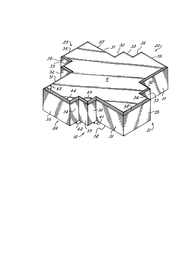
Referring to Figs. 1 and 2, a paving
stone 10 according to one preferred embodiment of
the present invention is illustrated. The stone 10
has parallel planar top and bottom surfaces 11 and
12, respectively, that are polygonal in shape, each
having four multi-faced sides which define upper
and lower edges of respective side surfaces 21-24
of the stone 10. Each of the side surfaces 21-24
has five faces 31-35, two end ones of which, 31 and
35, are longer or major faces, and three interior
ones of which, 32-34, are shorter or minor faces.
In this preferred and illustrated
embodiment, the two major faces of each side
sulrface, 31 and 35, are identical in length and
parallel to each other. The major faces 31 and 35
of opposite side surfaces, 21 and 23, and of the
opposite side surfaces 22 and 24, are also parallel
to each other, with the major faces of side
surfaces 21 and 23 being perpendicular to those of
side surfaces 22 and 24.
The minor face 33 of each side is a
central internal face parallel to the major faces
- 31 and 35 of the respective side surface, and lies
between and is adjacent to the two minor
20 8~0 ~ 3
- 14 -
interconnecting interior faces 32 and 34 of such
side surface. The interconnecting faces 32 and 34
of this embodiment are perpendicular to the minor
face 33 and thus also the major faces 31 and 35 of
the corresponding side.
Angle 41 between the major face 31 and
the minor face 32, and angle 42 between the minor
face 34 and the major face 35, are internal right
angles, in the preferred and illustrated
embodiment, while all other angles, including angle
43 between the minor faces 32 and 33, angle 44
between the minor face 34 and major face 35, and
corner angle 45 between major faces 35 and 31 of
adjacent sides, are external right angles.
In the preferred and illustrated
embodiment, the ratio of the lengths of the major
faces to the lengths of the minor faces is 3:1, but
any practical ratio is beneficial. The preferred
limits of the practical range of ratios is from 1:1
to 20:1, however, ratios in the range of from 2:1
to 8:1 are preferred.
Each of the faces 31-35 of each of the
side surfaces 21-24 may have a beveled edge 50
between the face 31-35 and the top surface 11 of
the stone 10 to emphasize the overall shape of the
stone 10 in the formation of patterns.
Additionally, internal and false edges may be
?08801 3
provided by V-grooves or similar features in the
top surface 11 to provide an aesthetic effect in
the pattern that is different from that provided by
the shape of the stone 10 alone.
The paving stone 10 of Figs. 1 and 2 is
preferably generally square in dimension with all
of the four side surfaces 21-24 being equal. It is
not necessary, however, that all of the sides 21-24
be equal but only that the opposite sides 21 and
23, 22 and 24 be equal and mirror images of each
other, though they are preferably also symmetrical
about their centers and thus identical. Similarly,
the major faces 31 and 3S are preferably of equal
length for all side surfaces, and the minor faces
- 15 32-34 are preferably are of equal length for all
- side surfaces.
The overall dimensions of the stone
should be such that a workman can handle stones in
one hand without tiring. Preferably, the stones
are approximately the size and weight of a standard
brick or are slightly larger, preferably 7-10
inches in maximum dimension, and preferably 1/5 to
2/5 of the overall dimension in thickness, the
thickness being the distance between the upper and
lower faces 11 and 12.
Referring to Fig~ 3, a plurality of
paving stones 10 are illustrated arranged in a
20880 1 3
- 16 -
closed pattern. In the pattern of Fig. 3,-the
sides 21 and 23 of adjacent stones are adjacent and
the sides 22 and 24 of adjacent stones are
adjacent. So arranged, each of the sides has major
faces 31 adjacent a major face 35 of an adjacent
stone, minor faces 32 and 34 are adjacent the minor
faces 34 and 32, respectively, of an adjacent
~ stone, and minor face 33 adjacent a minor face 33
of the adjacent stone. The pattern of Fig. 3
provides minimal drainage, only to the extent of
that presented in the nominal spacing between
adjacent faces of the adjacent stones.
Fig. 4 illustrates the paving stones 10
laid in an open pattern which provides open areas
Sl which constitute approximately 9 1/2% of the
area covered by stone 10, the area 51 is filled
with loose a~,egdte such as sand for drainage. In
the pattern of Fig. 4, the sides 21-24 of the
stones lOa-lOd are oriented as with the pattern of
Fig. 3, except that, as seen with respect to stone
lOb, for example, only a portion 52 of the face 35
of side 21 is adjacent face 33 of side 23 of
adjacent stone lOd, while face 34 of side 21 of
stone lOb is adjacent face 34 of side 23 of
2S - adjacent stone lOd. Further, face 32 of side 21
of, for example, stone lOa, and face 32 of slde 23
of stone lOd are each bounding a small side of the
208~0 1 3
rectangular space 51, with a portion of face 35 of
side 21 of stone lOb and face 31 of side 21 of
stone lOa bounding one long side of a space 51,
with face 31 of side 23 of stone lOd and a portion
of face 35 of side 23 of stone lOc bounding the
opposite long side of space 51. Sides 22 and 24 of
adjacent stones, in the pattern of Fig. 4, have
their faces adjacent the same corresponding faces
as with the pattern of Fig. 3.
Referring to Fig. 5, another open pattern
of the stones 10 is illustrated. In the pattern of
Fig. 5, the stones 10 are offset in both the
longitudinal and transverse directions such that
the faces of adjacent stones, sides 21 and 23, as
well as those on the sides of 22 and 24, abut each
other as the sides 21 and 23 of the stones abut in
Fig. ~. In the pattern of Fig. 5, a cross-shaped
space 55 is formed which is filled with loose
material such as sand, to present a drainage area
of about 23% of the area covered by the stones 10.
Fig. 6 illustrates another opened pattern
formed by a plurality of the paving stones 10. In
the pattern of Fig. 6, the face 33 of side 22 of
stone lOa abuts a portion 61 of face 31 of side 24
of adjacent stone lOb, while a portion 62 of a face
35 of side 22 of stone lOa abuts face 34 of side 23
of adjacent stone ~Oc. The remainder of the face
2~)880 1 3
- 18 -
35 of side 22 of stone lOa abuts a square drainage
space 63 representing a drainage area of a little
more than 7 l/2% of the surface area covered by the
stones 10, while the remainder of the faces 31 of
sides 22 of stones lOa and lOb, as well as faces 32
thereof, bound a rectangular drainage space 64
which represent a little less than 4% of the area
covered by the stones 10. The combined area of
spaces 63 and 64 representing somewhat more than
11% of the area covered by the stones. In the
pattern of Fig. 6, the stones are offset in a
similar fashion in both the longitu~in~l and
transverse directions.
Referring to Fig. 7, an additional open
pattern formed by the paving stones 10 is
illustrated. In the pattern of Fig. 7, pairs of
the~ stones 10 are arranged with sides 21 and 23
adjacent in the closed arrangement described in
connection with Fig. 3. In Fig. 7, these pairs
are, for example, pairs 90a-9Oe, each made up of a
stone lOa and a stone lOb. The pairs of stones lOa
and lOb are arranged, for example, with the face 35
of side 21 of stone lOb of pair 90d adjacent of
face 35 of side 23 of stone lOa of pair 90b, and
face 31 of side 21 of stone lOb of pair 90d
adjacent face 31 of side 23 of stone lOa of a pair
9oa. This arrangement is continued for the other
- 208801 3
_ ~9 _
pairs of stones lOa and lOb. The pattern that is
formed leaves one elongated drainage area 67 for
each pair of stones. The drainage areas 67 make up
approximately 21% of the area covered by the stones
s in the pattern. Each drainage area 67 is bounded,
for example, by faces 34 and 33 of side 21 of stone
lOb of pair 90d, a portion of face 35, face 34,
face 33, face 32 and face 31 of side 24 of stone
lOa of pair 90a, all of the faces of side 24 of
stone lOb of pair 90a, faces 34 and 33 of side 23
of stone lOa of pair 9oe, a portion of face 35,
face 34, face 33, face 32 and face 31 of side 22
stone lOb of pair 90b, and all of the faces of side
22 of side 22 of stone lOa of pair 90b.
Referring to Fig. 8, a further open
pattern formed by the stones 10 is illustrated. In
the pattern of Fig. 8, the sides of the stone, both
in the longitudinal and transverse directions, are
arranged such that the faces 35 of adjacent sides
of adjacent stones are adjacent. With this
pattern, the faces 31, 32, 33, and 34 of each of
the stones bound a drainage area 69 that is in
excess of 60~ of the area covered by the stones 10.
The stones of this do not effectively interlock, in
that no outside corner of one stone fits lnto an
inside corner of another. Thus, this type of
208~01 3
- 20 -
pattern is preferred only for limited load
applications.
Referring to Fig. 9, a further open
pattern formed by stones 10 is illustrated. In the
pattern of Fig. 9, the stones 10 are arranged in a
similar manner in both the longitudinal and
transverse directions, with only a portion 71 of
the faces 35 of adjacent sides of adjacent stones
in contact. With the pattern of Fig. 9, the stones
10 do not effectively interlock, but can be
arranged such that the portion 71 of the faces 35
that is in contact with an adjacent face 35 of an
adjacent stone is any amount of the face 35 and
will form a pattern with a drainage area 74 which
is in excess of 50% of the area covered by the
stones 10.
It is important that the sides of the
stones 10 have at least one step therein with at
least one interconnecting face separating two end
faces of the side. While some patterns can be
formed with stones having sides of a single step,
it is much preferred that the sides or at least one
set of opposite sides have a plurality of steps
therein for better interlocking of the adjacent
stones, more positive setting of the drainage
spaces as with the patterns of Figs. 4, 5 and 6,
and greater variety in the number of different
20~01 3
patterns with different drainage ratios that can be
formed. A provision of more steps in the sides of
the stones 10 will provide a greater number or
different configurations of positive spacings of
the drainage areas and a greater variety of easy to
lay discreet interlocking patterns, each of which
has a specifically ascertainable drainage area
ratio.
Principles of the present invention can
be applied in alternative embodiments to those
described above, as for example, with the stone 100
of Fig. 10. As shown in Fig. 10, a stone 100 is
provide having a pair of opposite and identical
lateral side surfaces 101 and 103, and a pair of
opposite and identical longitudinal surfaces 102
and 104. The faces of the side surfaces 101 and
103 are similar to those of the figures described
above, are placed, in the pattern shown, adjacent
side surfaces of adjacent stones in a manner
similar to that of Fig. 3. In this embodiment,
some of the faces on the sides 101 and 103 are not
planar, as represented by the notches 105 in the
faces 106, although the faces, including the notch,
lie generally in a plane. The notches 105 may
- cooperate with notches in adjacent faces, or an
adjacent planar surface, to produce an additional
drainage space. In addition, the side surfaces 102
20880 1 3
- 22 -
and 104 have both outward and inward steps, that
is, do not have the interior and exterior angles
alternating across the width of the side surface,
producing upward and downward steps at 107 and 108,
for example. In this embodiment, the angles are
not right angles, but those on the lateral side
surfaces 101 and 103 are acute angles. On the
longitudinal side surfaces 102 and 104, where the
steps formed are not all in the same direction, the
angles joining the interconnecting faces, as for
example faces 111 and 112, are equal to the corner
angle that those interconnecting faces generally
face. For example, the angles joining the face 111
equal the corner angle 113, while those joining the
face 112 equal the corner angle 114. The obtuse
angles so formed are supplementary to the acute
angles. In the pattern shown in Fig. 10, drainage
spaces 120 are formed. other arrangements of the
stone 100 will yield drainage spaces of different
shapes and sizes.
It can be further seen that stones may be
formed, in accordance with certain principles of
the present invention, by combining two stones into
stones of one piece, as, for example, by joining
two stones lO into one stone 125 in Figs. 3, 4, and
- 7, or by joining s~ones lOa and lOc in Fig. 4 or
two stones lO in Fig. 5 to form a stone 126, or by
208~0 1 3
joining two stones to form stone 127 (with or
without the drainage space 64a) in Fig. 6, or by
joining two stones, lOb and lOa of different pairs
90 to form the stone 128, by joining two stones 10
to form the stone 129 in Fig. 8, or by joining
other combinations of two or more stones 10 (Figs.
1-9), stones 100 (Fig. 10), or other stones
according to the invention.
While the preferred embodiments of the
invention are described in detail above, it will be
apparent to those skilled in the art that
modifications and variations of the paving stone
may be made without departing from the principles
of the present invention. Accordingly, what is
. claimed is: