Note: Descriptions are shown in the official language in which they were submitted.
~'~
- 1 - CFO 8g57
1 Scan Interval Control in
Ink Jet Recording Apparatus
BACKGROUND OE ~HE INVENTION
Field of the Invention
The present invention relates to an ink jet
recording apparatus for per~orming recording by
ejecting ink droplets onto a recording medium using a
recording head having a plurality of ejection portions.
Related Backqround Art
In recent years, OA equipment such as computers,
wordprocessors, copying machines, and the like have
been widely spread, and many recording methods of
recording apparatuses therefor have been developed. Of
these recording apparatuses, an ink jet recording
apparatus has excellent features, i.e., allows easy
high-definition, high-speed, and low-noise recording at
low cost as compared to other recording methods.
Meanwhilej needs for color recordin~ have also been
increasing, and a large number of color ink jet
recording apparatuses have been developed, too. An ink
jet recording apparatus forms an image in such a manner
that an ink ejected from nozzles is attached to a
recording sheet. In order to increase the recording
speed, a head obtained by integrating a plurality of
ink ejection orifices as ink ejection portions and
nozzles is used as a recording head (to be referred to
..
,~ . .. - - - ' ':
': ~
~'
~8~
l as a mul-ti-head hereinafter) obtained by integrating
and arranging a plurality of recording elements, and a
plurality of multi-heads are normally used to achieve
color recording.
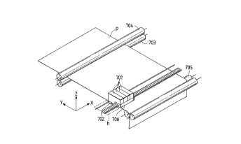
Fig. 1 shows an arrangement of a printer unik when
a print operation is performecl on a sheet surface using
the multi-head. Referring ~o Fig. 1, each of ink
cartridges 701 is constituted by an ink tank filled
with a corresponding one of four color inks, i.e.,
black, cyan, magenta, and yellow inks, and a multi-head
702. Fig. 2 shows the state o~ multi-nozzles 801 aligned
on the multi-head from the ~-direction. In Fig. 2, n
multi-nozzles are aligned on the multi~head 702.
Referring back to Fig. l, a paper feed roller 703 is
rotated together with an auxiliary roller 704 in a
direction of an arrow in Fig. 1, while pressing a print
sheet P, thereby feeding the print sheet P in the
y-direction. A paper supply roller 705 i8 used for
supplying a print sheet, and also serves to press the
prlnt sheet P as in the rollers 703 and 704. A
carriage 706 supports the ~our ink cartridges, and
moves these cartridges according to a print operation.
When the print operation is not performed, or when a
recovery operation of the multi-head is performed, the
carriage 706 stands by at a home position (h) indicated
by a dotted line in Fig. 1.
, "-,
,~
-- 3
2 ~
1 Upon reception of a print s-tart co~nd, the
carriage (706), which is located at the illustrated
position (home position) before the prlnt operation is
started, performs a print operation by a width L on a
sheet surface using n multi.-noz:zles (801) on -the rnul-ti-head
(702), while being moved in the x-direction. When the
carriage completes the data pri.nt operation up to the
sheet surface end portion, it returns to the home
position, and performs the print operation in the
x-direction again. During this interval after the
first print operation is ended and before the second
print operation is started, the paper feed roller (703)
is rotated in the direction of the arrow to feed the
print sheet by the width L in the y-direction. In this
manner, the prin~ operation and the paper feed
operation are repeated by the width ~ of the multi-head
for eac~ scan of the carriage, thus achieving the data
print operation on one sheet surface.
However, when a monochrome printer pxints an
image, various factors such as color development
characteristics, gradation characteristics, evenness,
and the like are required unlike in a printer for
printing only characters. In particular, as for the
evenness, a small variation in units o~ nozzles, which
may have occurred in a multi-head manu~acturing
process, influences the ejection amount and ejection
direction of the inks from the nozzles, and finally
, ~ ,
- ~ -
1 causes density unevenness of a printed image, thus
deteriorating image quality.
An example of density unevenness will be described
below with reference to Figs. 3A to 4C. In -this
example, a monochrome recording head is used for the
sake of simplicity. In Fig. 3C, a multi-head 91 is the
same as that shown in Fig. 1, and is assumed to be
constituted by eight multi-nozzles (92) for the sake of
simplicity. Ink droplets 93 are ejected from the
multi-nozzles 92. In general, it is ideal that the ink
droplets g3 are ejected in uniform ejection quantities
in the same direction, as shown in Fig. 3C. If such an
ejection is per~ormed, do~s having the same size land
on a sheet surface, as shown in Fig. 3B, and a uniform
image free from density unevenness is obtained
(Fig. 3A).
However, in practice, each nozzle suffers from a
variation, and when-the print operation is performed in
the same manner as described above, ink droplets
ejected from the nozzles have various sizes and
directions, and land on ~he sheet surface, as shown in
Fig. 4C. As shown in Fig. 4B, blank portions which do
not satisfy an area factor of 100%, portions where dots
unnecessarily overlap each other, and a white stripe
pattern (e.g., a pattern at the center of Fig. 4B)
periodically appear in the main scan direction of the
head. A group of dots which land in such a state have
1 a density dist~ibu~ion shown in Fig. 4A with respect to
the aligning direction of the nozzles, and
consequently, these phenomena are visually ~ensed as
density unevenness. In addition, a stripe patkern
caused by a variation in paper feed amount may
sometimes become conspicuous.
As a countermeasure against this density
unevenness-connection stripe, Japanese Laid-Open Patent
Application No. 60-107975 discloses the following
method for a monochxome ink jet recording apparatus.
The method will be briefly described below wlth
reference to Figs. 5A to 6C. According to this method,
the multi-head 91 is scanned three times to complete a
print area shown in Figs. 3A to 4C (Fig. 5C). However,
an area in units of four pixels, i.e., an area half a
print area is completed by two passes. In this case,
eight nozzles of the multi-head are divided into two
groups, i.e., upper four nozzles and lower four
nozzles. Dots printed by a single nozzle in a single
scan correspond to a pattern obtained by t.h;nning out
predatermined image data to about half according to a
predetermined image data arrangement. In the second
scan, dots are printed for the r~;ning half image
data, thus achieving the print operation of an area in
units of four pixels. The above-mentioned recording
method will be referred to as a divisional recording
method hereinafter.
-- 6
1 Using such a recording method, even when a head
equivalent to the multi~head shown in Fig. 4C is used,
since tho influences o~ the noz~les on a printed image
are halved, a printed image shown in Fig. 5B is
obtained, and black and white s~ripe patterns in
Fig. 4B do not become conspicuous. Irherefore/ density
unevenness is greatly reduced, as shown in Fig. 5A, as
compared to Fig. 4A.
Upon execution of such recording, in the first and
second scans, image data is divided into complementary
patterns according to a predetermined arrangemenk. As
the image data arrangement (thin-out pattern), as shown
in Fig. 6A, dots are printed at every other position in
the vertical and horizontal directions, i.e., a checker
pattern i5 most popularly used. Therefore, in a unit
print area (constituted by four pixels in this case),
the print operation is achieved by the first scan for
printing a checker pattern, and the second scan for
printing a reverse checker pattern. Figs.~6A, 6B, and
6C are views for expl~ining how to achieve a recording
operation of a predetermined area using checker and
reverse checker patterns and the multi-head having
eight nozzles like in Figs. 3A to 5C.
In the first scan, a checker pattern is recorded
using lower four nozzles (Fig. 6A). In the second
scan, a recording sheet is fed by a width corresponding
to four pixels (1/2 the head length), and a reverse
,
1 checker pa-ttern is recorded ( Fig . 6B ) . In the third
scan, the recordin~ shee-t is fed by another width
corresponding to four pixels (1/2 the head length)
again, and a checker pattern is recorded again
(Fig. 6C). In this manner, when the paper feed
operation in units of four pixels, and recording
operations of the checker and :reverse checker patterns
are alternately executed, a recording area in units of
four pixels is completed in each scan. As described
above, since a single print area is comple~ed by two
different groups of nozzles, a high-quality image free
from density unevenness can be obtained.
As another technical problem of the ink jet
recording apparatus, malformation and unexpected
coupling of dots which are formed upon landing of ink
droplets are known in association with absorption
characteristics and evaporation characteristics of the
ink on a recording sheet. Furthermore, in a color ink
jet recording apparatus for sequentially l~n~ i ng a
plurality of different color inks at overlapping or
adjacent dot positions, suppression of deterioration of
image quality caused by unexpected blurring or mixing
of the inks is known. The above-mentioned conventional
recording method is also effective for solving these
problems since the ink quantity ejected per record scan
is set to be small. A so-called multi-pass recording
method for ~inning out data by simply dividing a
~: ' ' ' :, ' ' . " '
' '' - . ~
.
3 ~
1 single image area into a plurality of xecord scans
without executing special paper feed control unlike in
the conventional recording method, and for executing
color-sequential recording is also proposed as a
countermeasure against the above-mentioned problems.
The conventional method can eliminate density
unevenness caused by landing precision (e.g., a
variation in nozzle positions) and the ejection
quantity, and can also solve image problems caused by
malformation of landing dots.
However, since an image is completed by a
plurality of number of times of record scans for a
single image area, the interval between adjacent record
scans may vary according to a time required for
recovery processing of a recording head, which
processing is performad during such interval between
adjacent record scans, or a time required for image
processing or transfer of image data to be recorded.
As a result, the landing times of adjacent dots on a
recording sheet vary in units of divided image areas,
and density unevenness caused by different
penetration-fixing states of the ink on the recording
sheet may occur. '
Figs. 7A to 7D show the landing-fixing state of
the ink on a recording sheet. Figs. 7A to 7D reveal
that the degree of fixing of a previously landed ink
influences the fixing state of an ink which lands on a
.
. .
1 recording sheet next. More specifically, when the
previously landed ink is sufficiently fixed, it always
presents a s~ate similar to a black-painted ink
portion. However, when the previously landed ink is
not sufficiently fixed, the next landed ink reaches
slightly under the previously landed ink, as indicated
by a hatched portion in Fig. 7D, resulting in a
different fixing state.
Such scan interval density unevenness is further
outstanding in color recording. When a solid prin~
operation of an intermediate color formed by printing
different color inks at proper overlapping or adjacent
dot posi~ions is performed, considerable color shading
occurs.
Color development, which is important in color
recording, will be described in detail below. When a
dot is printed to overlap a previously recorded dot,
the dot recorded latex tends to penetrate deeper in the
direction of depth of the sheet than the previously
recorded dot, and tends to blur around the previously
recorded dot. The same applies to a case wherein a new
dot is printed adjacent to a previously recorded dot.
Figs. 7A to 7D are sectional views illustrating the
spread of the ink when a new dot is printed adjacent to
a previously recorded dot.
The above-mentioned tendency appears for the
following reason. That is, a coloring material such as
.~........ ,
: ' .
-- 10 --
~8~
1 a dye in the e~ected ink is physically and chemically
coupled to a recording medium. At this time, since
coupling b~tween the recording medium and the coloring
material is limited, coupling between the previously
ejected ink coloring material and the recording medium
has priority as long as there is no large difference in
coupling force depending on thle types of coloring
materials. For this reason, the previously ejected ink
coloring material remains in a large quantity in the
surface portion of the recording medium, and the ink
coloring material printed next is difficult to couple
in the surface portion of the recording medium, and
penetrates in the direction of depth of the sheet and
is fixed. This is because a difference in dot form
associated with color development between a new dot
which lands on an image area where an ad~acent dot has
been pre-recorded, and a dot which lands on an image
area where no dot is recorded appears as a difference
in color tone between image areas since the number of
landing dots per scan varies in units of image areas.
As described above, in a conventional L/n paper
feed print method, since the number of l~n~ing dots per
record scan varies when a print operation for a single
image area is achieved by a plurality of number of
times of record scans, undesirable color shading occurs
in a mixed-color recorded portion, resulting in
deterioration of a color recorded image. In the
~ .
ll -
2 ~
1 conven-tional L/n paper feed print method, in order -to
eliminate d~nsity unevenness caused by a variation in
noz~les, the required number of times of record scans
must be almost doubled, resulti.ng in a decrease in
recording speed.
In order to increase the recordin~ speed,
back-and-forth scan recording ~lay be proposed. In this
case, as a problem inherent to color ink jet record:ing,
a technical problem, i.e., a difference in color tone
caused by a back-and-forth difference in landing order
of inks is posed. More specifically, back-and-forth
scan recording has already been put into practical
applications in a monochrome ink jet recording
apparatus. However, when color recording is performed,
since the landing order of color inks is reversed in
forward and backward scans, a difference in color tone
between image areas occurs like in the above-mentioned
case, and this method has not often been put into a
practical application. This is because the ink which
lands later spreads around and in the direction of
depth of the previously landed dot, as described above.
A recording method for reducing a difference in
color tone in the back-and-forth recording is disclosed
in Japanese Laid-Open Patent Application No. 58-194541.
This method is effective for a so-called solid image in
which color dots are recorded in a predetermined area
at high density. However, in halftone image data,
- 12 -
1 which req~l.ires area-g.rad~-tion r~cording, since an image
itself to be recorded is orig.inally thinned out
according to a predetermined g:radation pattern so as to
achieve gradation expression, the gradation pattern
interferes with a thin-out pattern for each
back-and-forth record scan, thus causing the
above-mentioned color shading. Although two, i.e.,
back and forth record scans are performed for a
predetermined image area, densi-ty unevenness caused by
a variation in nozzles cannot be removed, and a simple
application of this method is difficult to achieve.
For this reason, the recording method is not put into a
practical application yet.
SUMM~RY OF ~HE lNV~NllON
The present invention has bPen made to solve the
above-mentioned problems, and has as its object to
provide an ink jet recording apparatus, which can
prevent generation of scan interval density unevenness,
and can satisfactorily perform image recording in a
recording method such as a divisional recording method
in which a recording operation for a single image area
is achieved by a plurality of numbex of times of record
scans.
It is another object of the present invention to
provide an ink jet recording apparatus, which can
prevent generation of scan interval density unevenness,
and can satisfactorily perform image recording in color
,. ~ .
- 13 -
1 recording, especi~lly in back-and-Eo:r~h color recording
as well.
It is still another object of the present
invention to provide an ink jet recording apparatus,
which can prevent generation of scan interval density
unevenness, and can satisfactorily perform image
recording even when recovery processing is performed
during recording.
In order to achieve the above objects, according
to the present invention, there is provided an ink jet
recording apparatus for performing recording using a
recording head having a plurality of ink ejection
portions, comprising: image forming means for
completing image formation by complementarily
performing a plurality of number of times of record
scans for an image area, the image area corresponding
to each of sections obtained by dividing a recording
section of the recording head; and scan interval
management means for controlling an interval between
adjacent record scans of the recording head~ the scan
interval management means controlling scan intervals,
so that a difference between scan intervals of
continuous record scans of the plurality of number of
times of record scans for a single image area by the
image forming means falls within a predetermined time
range.
~z ~
1 There is also p:rovi.ded an ink jet recording method
for performlng recording using a recording head having
a plurality of ink ejection portions, comprising the
steps of: performing first recording on an image area
by scanning the recording head, the image area
corresponding to each of sections obtained by dividing
a recording section of the recording head; causing the
recording head to wait for a predetermined period of
time after the first recording step; performing second
recording on the image area by scanning the recording
head after the waiting step, the recording in the
second recording step complementing the recording in
the first recording step; and repeating the second
recording step and the waiting step to complete an
image on the image area, wherein the waiting step
includes the step of causing the recording head to wait
for the predetermined period of time, so that a
difference between scan intervals of the continuous
recording steps of the recording steps for the image
area falls within a predetermined time range.
Furthermore, there is provided an ink jet
recording apparatus comprising: a recording head,
having a recording section (L), for ejecting an ink
from a plurality of ink ejection portions; image
forming means for completing image formation on n image
areas divided in correspondence with the recording
section (L) of the recording head by executing
,
_ 15 -
1 recording in a plurality of number of times of record
scans of the recording head using a plurality of
complementary ~hin-out patterns, and se~uentially
executing a paper feed operation by an L/n width; and
scan interval management means for limiting a variation
in scan intervals of the plurality of number of times
of record scans for a singl~ image area by the image
forming means to fall within a predetermined time
range.
BRIEF DESCRIPTION OF T~IE DRAWINGS
Fig. 1 is a schematic perspective view for
explaining an ink jet recording apparatus to which the
present invention can be applied;
Fig. 2 is a partial explanatory view of a
recording head to which the present invention can be
applied;
Figs. 3A to 3C are views showing an ideal print
state of an ink jet printer;
Figs. 4A to 4C are views showing a print state of
an ink jet printer suffering from density unevenness;
Figs. 5A to 5C are views for expl~i n; ~g
elimination of density unevenness by an L/n paper feed
print method;
Figs. 6A to 6C are views for explaining
elimination of density unevenness by the L/n paper feed
print method;
- 16 --
~88~
I Figs. 7A to 7D are sectional views of a recording
medium for explaining an overlapping state of dots;
Fig. 8 is a schematic explanatory view of a
recording method according to the first embodiment of
the present inventLon;
Figs. 9 to 11 are views showing dot formation
states in the first to third scans in the first
embodiment;
Fig. 12 is a view showing an example of image
data;
Fig. 13 is an explanatory view of a thin-out
method of the first embodiment;
Fig. 14 is a table showing estimation results of
scan interval density unevenness in color recording;
Fig. 15 is a block diagram showing a control
arrangement of an ink jet recording apparatus of the
first embodiment;
Fig. 16 is a flow chart showing scan interval
management in the first embodiment;
Figs. 17 and 18 are explanatory views of record
scans in a wiping mode in the first and fourth
embodiments;
Fig. 13 is an explanatory view of record scans in
a normal mode in the first and fourth embodiments;
Fig. 20 is a table showing record scan intervals
in a pre-ejection mode in the first embodiment;
.
,~.
. .
- :
: . .. ~ ,;
- ]7 -
2 ~
1 Fig. 21 is an explanatory view of another thin-out
method of -the first embodiment;
Fig. 22 is a table sho~ing astimation results of
scan interval density unevenness in monochrome
recording in the first embodiment;
Fig. 23 is an explanatory view of a thin-out
method of the second embodimerlt;
Figs. 24 to 29 are schematic explanatory views of
recording methods according to the second and fifth
embodiments of the present invention;
Figs. 30 to 38 are explanatory views of record
scans in a recording interruption mode for a long
period of time in the second and fifth embodiments;
Fig. 39 is an explanatory view of record scans in
a normal mode for a long period o~ time in the second
and fifth embodiments;
Fig. 40 is a flow chart showing scan interval
management using a scan interval timer in the third and
sixth embodiments;
Figs. 41 to 43 are views showing dot formation
states in the first to third scans in the fourth
embodiment;
Fig. 44 is a table showing estimation results of
scan interval density unevenness in color recording;
Fig. 45 is a table showing record scan intervals
in a pre-ejection mode in the fourth embodiment; and
~ ' ,
:'
' .
0 2 1
1 Fig. 46 is a -table showing estimation results of
scan interval density unevenness in monochrome
recording of the fourth embodiment.
: DESCRIPTION OF THE PREFERRED EMBODIMENTS
The preferred embodiment of the present invention
will be described in de~ail he:reinafter with reference
to the accompanying drawings. In this emhodiment, a
black ink (to be abbreviated as Bk hereinafter), a cyan
ink (to be abbreviated as Cy hereinafter), a magenta
ink (to be abbreviated as M hereinafter), and a yellow
ink (to be abbreviated as Y hereinafter) are used like
in four ink jet cartridges mounted on the carriage 706
shown in Fig. 1 above, and the inks are overlaid in
this order. An intermediate color can be reali~ed by
properly overlapping Cy, M, and Y ink dots. In
general, black can be realized by overlapping three
colors, i.e., Cy, M, and Y. However, at this time,
black formed in thLs manner has poor color development,
and a chromatic edge is formed since it is difficult to
overlap the three ink dots with high precision. In
addition, the ink ejection density per unik time
becomes too high. For these reasons, only black is
separately printed (the black ink is used).
Fig. 8 shows the outline of the recording method
~f this embodiment. In this embodiment, color
recording is performed. Since scans are performed, as
indicated by a head scan direction (a) of Fig. 8, the
.
- ~ . -
. ,,; ~, :
:
,
:
:~ ;
- 19 -
1 ink prin~ order of in each record scan is Bk - Cy ~ M -
Y.
On the first image area, do~s are printed in a
pattern obtained by thinning out original image data in
a checker pattern using lower :half nozzles in recording
sections (1) of recording heads in the first scan
(Fig. 9). Then, a recording sheet is fed by an L/2
width. In the second scan, the recording heads print
dots in a pattern obtained by thinning out the image
data in a reverse checker pattern which complements the
checker pattern in the first scan, using upper half
nozzles in the recording section (1) and lower half
nozzles in the recording section (2). At this time, on
the first image area, dots are printed on recording
pixels, which are not printed in the first scan,
according to image data t.h; nnetl out to the reverse
checker pattern, thus completing image data recording.
The dots recorded on the first image area are printed
on recording pixels in the checker pattern, and are
then printed on recording pixels in the reverse checker
pattern, which complements the checker pattern
(Fig. 10).
The recording sheet is then fed by another L/2
width. Thereafter, in the third scan, image data is
thinned out to a checker pattern like in the first
scan, and dots are printed on a second image area using
the upper half no~les and on a third image area using
,
.
- 20 -
2 ~
1 the lower half nozzles. The recordinq operation on the
second image area is completed in the third scan. The
dots printed on the second image area are printed on
recording pixels in the reverse checker pattern, and
are then printed in the landing order on recording
pixels in the checker pattern, which complements the
reverse checker pattern (Fig. 11). When the same
operations are repeated, image areas divided in
correspondence with the 1/2 width (L/2 width) of the
recording heads are sequentially subjected to
recording, and the recording operation of all the image
data is completed. In Fig. 8, data in the parentheses
indicate previously printed portions.
In this embodiment, in order to uniform the number
of landing dots in each record scan, as shown in
Fig. 12 (head scan direction (a)), an inX jet recording
head having a recording density twice that of image
data is used, and one pixel of image data is recorded
while being divided into four recording pixels
subjected to the same recording operation. Using the
recording head having the recording density twice tha~
of image data like in this embodiment, when image data
is complemented using simple checker and reverse
checker thin-out patterns shown in Fig. 13 (head scan
direction (a)) in thin-out recording using the
recording head, the number of landing dots in each
record scan in each image area can be uniformed
- ,. . .
.
~ 21 -
2~8~
1 regardless of image data to be recorded. For this
reason, no density difference-color tone difference
between image areas caused by a difference in the
number of landing dots will occur.
In this embodiment, density unevenness caused by
landing precision (e.g., a var:iation in nozzle
positions) or the ejection quantity can be eliminated,
and an image problem caused by mal~ormation o~ landing
dots can also be solved.
However, since an image is completed by a
plurality of number of times of record scans for a
single image area, the interval between adjacent record
scans may vary according to a time required for
recovery processing of a recording head, which
processing is performed during the interval between
adjacent record scans, or a time required for image
processing or trans~er of image data to be recorded.
As a result, the landing times of adjacent dots on a
recording sheet vary in units of divided image areas,
and density unevenness caused by different
penetration.fixing states of the ink on the recording
sheet may occur. Such scan interval density unevenness
is further outstanding in color recording of this
embodiment. When a solid print operation of an
intermediate color formed by printing different color
inks at proper overlapping or adjacent dot positions is
performed, considerable color shading occurs.
- 22 -
1 In this embodimen-t, the recording section (L) of
the recording head is divided into n sections, ~nd the
recording operation is achieved by a plurality of
numher of times of record scans of the recording head
for each of image areas obtained by dividing the entire
image area in units of L/n widths, while a recording
sheet is sequentially fed by the L/n width. In
addition, a scan interval mana~ement means for limiting
variations of scan intervals of the plurality of number
of times of record scans for a single image area to
fall within a predetermined time range is arranged to
suppress scan interval density unevennes~. More
specifically, as the scan interval management means, an
image memory for the entire image area to ~e subjected
to divisional recording is provided, and the record
scan timing including a paper feed time and a recovery
processing time of the recording head is set in
advance.
(First Embodiment)
The scan interval management of this embodiment
will be described in detail below. Fig. 14 shows
visual discrimination results of a density
difference-color tone difference when adjacent image
areas are subjected to recording in various
combinations of scan interval time differences, i.e.,
time differences between scan times for checker and
reverse checker print operations on the image areas
- 23 -
~8~s~
1 upon color recording. In this table, O represents a
case wherein no density difference.color tone
difference is observed at all, ~ represents a case
wherein no problem is posed in actual use although a
slight density dif~erence.color tone difference is
notified if a printed image is observed carefully, and
x represents a case wherein a density difference-color
tone difference is obvious~ and a printed image is
unfit for actual use. In Fig. 1~, when scan intervals
for the checker and re~erse checker print operations
are equal to each other, no problem about the density
difference.color tone difference is posed. However, as
another problem, when the absolute value of the scan
interval becomes large, a stripe pattern having a
relatively high density may often be observed at a
connection part between adjacent scans. For this
reason, it is preferable that the scan interval is not
increased too much. However, as the absolute value of
the scan interval becomes larger, an allowable range of
the density difference.color tone difference with
respect to a scan interval difference tends to widen,
and a long scan interval i5 advantageous in this
respect.
The control arrangement of this embodiment will be
described below with reference to Fig. 15. A color ink
jet recording apparatus 501 of this embodiment
comprises an image data memory 503 for storing image
'
~ 2~ -
~80~
1 data for one A~-size page, which data is supplied from
a host apparatus 502. A CPU 504 can check all image
data before recording is started. When the
above-mentioned print mode for sequentially completing
an image by the plurality of number of times of scans
is desi~nated, the CPU 504 d~termines in advance an
ejection condition of a recording head 505 on the basis
of image data, and sets an optimal timing of recovery
processing (e.g. r pre-ejection and wiping) of a
recovery system 506 according to the ejection
condition. Thereafter, the CPU 504 sets in advance
record scan timings as well as recovery processing
timings and paper feed timings with reference to
Fig. 14 so as not to cause scan interval density
unevenness, and then starts recording. The record scan
timings are managed by controlling the driving start
timings of a head driver 508 by a scan interval manager
unit 507, and image data for one scan is supplied from
a print data register 509 to the head driver 508.
In this embodiment, the paper feed time is fixed,
and the time required for each record scan is also
fixed since all the areas are subjected to recording at
the same recording speed. In addition, image data is
stored in advance in the image data memory 503 after it
is subjected to image processing to have a format
suitable for recording. Therefore, the scan interval
mainly varies according to the recovery processing
,
- 25 -
~8~
l timing. of course, as a modification of this
embodiment, when a variable paper feed speed can be set
or a variable scan area can be set according to image
data, or when the record scan timings are set on the
S basis of image data transferred from a host apparatus
in consideration of an image p;rocessing time in
addition to the recovery processing time, and the image
processing can be sequentially performed while
executing recording, the record scan timings may be set
in consideration of the times requires for these
operations.
In this embodiment, the record scan timings are
set after the recovery processing timings are set. In
this embodiment, as recovery processing during a print
operation, pre-ejection, which is performed as needed
between adjacent record scans according to the number
of recording dots and the recording time, and requires
0.5 sec, and wiping, which is performed as needed
between adjacent record scans according to the number
of recording dots, and requires 2.5 sec, are normally
performed. A timing required for wiping is longer than
that required for pre-ejection, and pre-ejection for
preventing color mixing by wiping is performed afker
the wiping. For this reason, in the record scan timing
setting flow shown in Fig. 16, the wiping timing is set
first.
'' ' . ' : '
.. ~
.
.. . . .
26
2 ~
1 In this ~rnbodiment, when a-t least one of four
color recording heads (360 DPI, 64 nozzles) has ejected
five million dots or more, -the wipiny is simultaneously
performed for all the four color recording heads before
the next record scan. More specifically, every time
dots in a single color are formed on pixels half those
for one A4-size page, wiping is executed. Ther~fore,
no wiping may be performed within one page depending on
image data, and conversely wiping may be performed a
10 m~ of twice within one page. In this embodiment,
in processing for converting image data transferred
from the host apparatus 502 in step S11 into data
suitable for recording in step S12, the numbers of dots
in units of recording heads 505 are counted by an
electrical hardware circuit, and wiping timings are set
(step S13).
When non-recording pixels continue for forty
thousand dots or more in units of nozzles of at least
one of the recording heads 505, pre-ejection from all
the nozzles of all the four color recording heads is
performed onto a pre-ejection pad in units of 16 dots.
More specifically, if a color recording head, which has
no recording dots corresponding to an area about l/5
one A4-size page is found, it is set to execute
pre-ejection (step S14). When a monochrome mode is set
as the recording mode, or when some recording heads
record no dot within one page, these recording heads
.
. .
, ~. - : . :
' ' ' : ~ :
.
~: ' ' . .
1 may be excluded from the setting operation of ~he
pre-ejection timings. Since the number of dots in
pre-ejection including the pre--ejection (in units o~
100 dots for each nozzle) after wiping is considerably
smaller than the number of dots for setting the wiping
timing, the wiping timing is not re-corrected according
to the number of times of pre-ejections in this
embodiment. However, the wiping timing ma~ be
corrected in consideration of parameters including the
wiping timing.
The setting operation of the record scan timings
in step S15 will be described below. In this
embodiment, the unit record scan time including the
paper feed time and excluding the recovery processing
time is constant, i.e., 1.2 sec. Therefore, when the
pre-ejection (required time = 0.5 sec) is performed
after a given scan, the record scan time requires 1.7
sec (1.2 ~ 0.5); when the wiping is performed, it
requires 3.7 sec (1.2 -~ 2.5). There~ore, as shown in
Fig. 14, scan interval density unevenness occurs in
this state, and image quality is considerably
deteriorated.
In this embodiment, the record scan timings are
set so as not to deteriorate image quality before
recording is started. In this embodiment, different
record scan timing correction methods are selected with
reference to the degree of image deterioration in
' ' '' "
.' "
' . ~
- 28 -
8 1~ 2 1
1 Fig. 14 in correspondence with the pre-ejection mode
and the wiping mode, respectively.
In the wiping mode, since the time difference from
the normal scan time becomes large, the density
difference.color tone di~ference becomes conspicuous.
For this reason, an image in an image area associated
with the wiping timing is form~ed before wiping, and
after the end of wiping, recor~ing on the next image
area is started. The following description will be
made with reference to Figs. 17 to 19 as in the above
description of the recording method. The head scan
direction is indicated by (a) in Figs. 17 to 19.
For example, when wiping is planned upon
completion of the 48th scan for performing image
formation on the 47th and 48 h image areas, no
recording is performed on the 48th image area in the
48th scan, and an image in the 47th image area is
completed using the upper half nozzles in the recording
section (2), as shown in Fig. 17. Upon completion of
the 48th scan, wiping is executed, and recording is
performed on the 48th image area by the recording
section tl) using the lower half nozzles in the 49th
scan, as shown in Fig. 18. During this interval, no
paper feed operation (L/2 width) is performed, and upon
completion of the 49th scan, a paper feed operation
(L/2 width) :is performed. Thereafter, in the 50th
scan, an image in the 48th image area is comple-ted, and
; : .
, , :, :
.
.. . .
.
,
.
29 --
~ ~ ~ ?3 ~
I new recording Ls performed on the ~9-th image area.
Therefore, in this ernbodiment, the number of times of
record scans is increased by one when the wiping is
executed. Note that Fig. 19 shows a recording state in
the ~8th scan when no wiping i8 executed.
Since the scan interval upon execution of
pre-ejection has a relatively small time difference
from the normal scan interval, the density
di~ference-color tona difference is not conspicuous.
In addition, the frequency of pre-ejection is higher
than that of wiping. For these reasons, in order to
eliminate the density di~ferenceocolor tone difference
without increasing the number of times of scans, the
scan intervals are gradually increased toward a record
scan corresponding to the execution timing of
pre-ejection according to the table shown in Fig. 14,
and the scan intervals after execution of pre-ejection
are gradually decreased. For example, as shown in
Fig. 20, when pre-ejection is prearranged after
completion of the 32nd scan, a wait time of 0.1 sec is
sequentially added to the basic scan time (1.2 sec)
from the 28th scan, so that a total wait time of 0.4
sec is added to set the scan time of 1.6 sec in the
31st scan. Contrary to this, the wait time is
gradually subtracted from the scan time by 0.1 sec from
the 33rd scan, so as t~ restore the normal scan
interval (1.2 sec) from the 37th scan. As described
- 30 -
2~g~
1 above, since the ~ecord scan intervals before and after
the scan i~terval (1.7 sec) upon execution of
pre-ejection are caused to gradually approach the
target scan in-terval, any diff~erence between adjacent
image areas where the density difference-color tone
difference i6 particularly conspicuous can be
decreased. Therefore, an image free from such a
problem can be formed.
In order to set a constant scan interval, each
record scan may be performed to have the longest scan
interval, i e., the scan interval (1.7 sec) upon
execution of pre-ejection, so that scan interval
density unevenness can be prevented. However, since
the recording time is increased with this method, the
method of this embodiment is more advantageous.
Note that Japanese Laid-Open Patent Application
No. 63-312155 discloses a technique for providing a
predetermined time difference to scan intervals so as
to prevent dots from being mixed. ~owever, this patent
application gives no suggestion about density
unevenness caused by variations of scan intervals.
In this embodiment, as described above, different
timing correction methods are adopted in correspondence
with the wiping mode and the pre-ejection mode,
respectively. However, in an ink jet recording
apparatus in which the degree of scan interval density
unevenness or the time required for recovery processing
: . :
.
.
' ~ :
,
- 31 -
~802~
l varies according to ink characteristics or absorption
characteristics of a recording sheet, either one of the
methods may be adopted. Furthermore, one of these
methods may be selected accord:ing to the recording
sheet or the print mode. In the above-mentioned case,
when no wiping is executed, and only pre-e~ection is
executed, constant scan intervals equal to or slightly
shorter than the scan interval upon execution o~
pre-ejection may be set so as not to cause a
conspicuous density difference.color tone difference.
As described above, in this embodiment, color
image recording can be satis~actorily realized without
causing scan interval densi~y unevenness, which tends
to occur upon printing of a solid image in mixed color,
in such a manner that different color inks are printed
at proper overlapping and adjacent positions, while
utilizing the feature of the Lin paper ~eed print
method, which can el; in~te density unevenness caused
by landing precision (e.g., a variation in nozzle
positions) and the ejection quantity. Therefore, image
quality can be improved.
In this embodiment, the print operation is
performed based on image data thinned out to a simple
checker pattern such as checker and reverse checker
patterns. However, the thin-out pattern is not limited
to the checker pattern since image data need only be
thinned out to obtain almost uniform numbers of dots in
2~8~
1 units of record scans in the present invention. More
specifically, the recording sections (1) and (2) need
only have a complementary relationship therebetween,
and the numbers of dots upon execution of divisional
recording of image data need only be almost equal to
each other.
In this embodiment, the thin-out ratio in each
recording section of each recording head is set to be
50~, and an image to be recorded is completed by two
scans. When the ink ejection quantity is to be
increased to increase the print density, the thin~out
print ratio in each section may be set to be 75% to
achieve a ratio o~ 150% by two scans although the
thinned-out image data in this case do not become
faithful to original image data. Contrary to this,
when the ink ejection quantity ifi decreased to
eliminate blurring at a boundary of inks, the thin-out
print ratio may be set to be, e.g., 40~, so that the
ejection quantity may be suppressed to 80% by two
scans. For example, the ink ejection quantity is
decreased by th; nn i ng out recording pixels without
adversely affecting image data, as shown in Fig. 21,
and the numbers of dots in units of record scans can be .
uniformed.
In this embodiment, since the recording head
having the recording density twice that of image data
is used, the number of recording dots in each scan is
: :
- 33 -
~ ~ 8 '~ J
1 the same. In contras-t to this, thin-out multi-pass
recordin~ may be performed while the thin~out method is
set, so that the number of recording dots in each scan
are the same after pixel density conversion for
decreasing the pixel density of image data to l/2 or
less in at least one direction is executed. In this
case, the pixel density conversion and generation of
thinned-out image data may be performed by the ink jet
recording apparatus main body, or may be performed by a
host apparatus such as a personal computer for
transmitting image data in correspondence with the ink
jek recording apparatus.
Furthermore, this embodiment exemplifies the
divisional recording method with the L/2 paper feed
operation. However, the present invention can also be
applied to a multi-pass recording method wherein a
single image area is subjected to a plurality of number
of times of scans without executing the paper feed
operation. In this case, scan interval density
unevenness between adjacent image areas can be
eliminated.
Fig. 22 shows visual discrimination results of a
density difference when adjacent image areas are
subjected to recording in various combinations of scan
interval time differences, i.e., time differences
between checker and reverse checker print operations on
the image areas upon monochrome recording. In Fig. 22,
-
- 3~
1 the discrimination results are expressed by the same
estimation criterions as -those in Fig. 14. In the case
of monochrome recording, the allowable range of -the
scan interval difference associated with the density
di~ference is relatively wider than that in the color
recording. Therefore, the record scan timing
correction in the above embodiment can be relatively
simplified. For example, correction upon execution of
the pre-ejection may be omitted. More specifically,
different scan interval management methods may be
selected in correspondence with the color recording
mode and the monochrome recording mode, respectively.
In this embodiment, the ink jet recording
apparatus having the image memory for one A4-size page
has been exemplified. When the capacity o~ the image
memory is smaller than one A4-size page, the record
scan intervals may be set for each recording image area
according to the capacity of the image memory, and
thereafter, the print operation may be sequentially
executed. In this case, the recovery timings are set
by accumulating information associated with recovery
processing, and the same record scan as that in the
wiping mode is executed at the final line of the
recording image area according to the capacity of the
image memoryr thereby eliminating scan interval density
unevenness caused by the data transfer wait time or the
image processing time.
': : , '' :
' :
- 35 -
'2 ~
1 (Second Embodiment)
Fig. 23 and Figs. 24 to 2g show a recording method
according to the second embodiment of the present
invention.
In this method, a recording section (L) of each
recording head is divided into four sections. Each
recording head records recording pixels thinned out to
25% in the first scan, and thereafter, a recording
sheet is fed by an I,/4 width. In the second scan, each
recording head prints another 25% recording pixels
using different nozzles, and the recording sheet is fed
by another L/4 width. In the third scan, each
recording head prints still another 25% recording
pixels, and the recording sheet is fed by another L/4
width. In the fourth scan, each recording head prints
the L.. '; n ing 25% recording pixels, thus completing the
print operation.
Fig. 23 shows an example of a 25% thin-out method
in this embodiment, and illustrates 4 x 8 recording
pixel thin-out patte.rns in units of scans. In Figs. 24
to 29, ejection orifice arrays are viewed from the
above for the sake of simplicity although they cannot
be seen in the illustrated direction in practice.
Image data and recording heads are the same as those in
the first embodiment. In Figs. 23 to 29, the h=ad scan
direction of this embodiment is indicated by (a).
'
; . : . : ., -
~ ' .
- 36 -
8~2~
1 A further detalled explanation will be given with
reference to Figs. 24 to 29. In the first scan, dots
thinned out to 25% are printed on the first image area
using nozzles in a recording section (1) of each
recording head. At this time~ in the 25% thin-out
method, pixels corresponding to the positions in the
(4n-3)th scan shown in Fig. 23 are printed, and dots
are formed on a sheet surface in an arrangement of
recording pixels shown in Fig. 24. Then, a .recording
sheet is fed by an L/4 width, and the first image area
sub~ec~ed to recording by the recording section (1) is
shifted to a recording section (2). In the second
scan, dots are printed on the second and first image
areas according to a thin-out pattern of the (4n-2)th
scan shown in Fig. 23 using nozzles in the recording
sections (1) and (2), respectively. Fig. 25 shows the
recording state in the second scan. Then, the
recording sheet is fed by another L/4 width, so that
the first image area is shifted to a recording section
(3), and the second image area is shifted to the
recording section (2).
Subsequently, in the third scan, the print
operation is performed on areas corresponding to the
recording sections (1), ~2), and (3), as shown in
Fig. 25. In the third scan, the recording operation is
performed according to a thin-out pattern of the
(4n-l)th scan shown in Fig. 23. The recording sheet is
.,"~
:
,
- 37 -
~ a ~
1 then fed by another L/~ width, and, as shown in
Fig. 27, -the recordin~ operation is performed according
to a pa-ttern in the (4n)th scan shown in ~ig. 23.
Thereafter, the recording operation continues, as shown
in Figs. 2~ and 29. Thereafter, the above-mentioned
paper feed op~ration and the head scan opera~ion are
sequentially repeated to achieve the recording
operation.
In Fig. 29, paying attention to the dot formation
state on the first to khird image areas on which
recording has already been completed, dots are formed
on recording pixels, where pixels of original image
data are adjacent to each other, in four different
record scans. For this reason, even when the
above-mentioned recovery processing is per~ormed in at
least one of the four record scans, the degree of
density difference-color tone difference caused by a
difference in scan interval becomes about half that in
the first embodiment. ~herefore, in this embodiment,
the scan interval difference upon execution of
pre-ejection does not so seri~lly influence the density
difference-color tone difference.
For this reason, in this embodiment, the record
scan timing is corrected as in the above embodiment
only when wiping is executed. Since the setting
operation of record scan timings is simplified, the
record scan timings can be easily corrected even if
.
- 3~ -
1 recovery p.rocessing timings are not set in advance.
For this reason, when wiping is required duriny
recording, an image in an image area, associated with
the wiping timing is completed before execution of the
wiping, and recording for the next image area is
started after the wiping i5 completed. For this
reason, scan interval density unevenness can be
suppressed even when an image clata memory has a small
capacity.
However, since this embodiment executes the
four-divisional print operation, a relatively
complicated record scan is required as follows so as to
complete an image before wiping unlike in the above
embodiment. Fig. 30 shows a normal record scan state
15 in the 96th scan. When a long scan interval is :
required since, for example, wiping is required upon
completion of the 96th scan, or since no image data is
transferred, record scans shown in Figs. 31 to 38 are
executed. Note that Fig. 39 shows a normal recording
state in the 97th scan, and the head scan direction is
indicated by (a). A detailed explanation will be given
below.
As shown in Fig. 31, in the 97th record scan for
partially completing recording, after a predetermined
paper feed operation (L/4 width), the recording
operation is performed on image areas before ~he 96th
image area, for which areas recording has already been
- :
- 39 -
2~8~
1 started. Similarly, in -the 98th record scan shown in
Fig. 32, after a predetermined paper feed operation
(L/4 width), the recording operation is performed on
the 96th and 95th image areas using -the recording
sections (3) and (4). In the 99th scan, the recording
operation is performed on the 96th image area using
only the recording section (3), as shown in Fig. 33,
without executing a paper feed operation. Therefore,
since the 96th image area is subjected to recording
using the same recording section twice in the
four-divided record scans, the effect of nozzle
unevenness reduction is relatively impaired but is
satisfactory as compared to the two-divi~ional
recording in the above embodiment. Thus, no problem is
posed in a practical use.
In this manner, after the image on the 96th image
area is completed, wiping or data waiting processing
for a long period of time is executed. After execution
of the wiping or necessary data is input, the record
scan is restarted. Fig. 34 shows a recording state in
the 100th record scan after the record scan is
restarted. Since no paper feed operation is performed,
the recording operation is performed on the 97th image
area using the recording section ~2). Subse~uently,
the 101st scan is executed to perform recording on the
97th and 98th image areas, as shown in Fig. 35, while
adjusting the scan interval timing without executing a
.. .
. . : . . .~ .. ~ .
- ~o -
1 paper feed operation. Thereafter, a predetermined
paper feed opera-tion (L/~ width) is performed, and
recording is performed using r~ecording sections ~1) to
(3), as shown in Fig. 36. ~hereafter, as shown in
Figs. 37 an~ 38, the normal record scan, i.e., khe
103rd and 104th scans are sequentially e~ecuted.
In this manner, according to this embodiment, scan
interval density unevenness can be efficiently
prevented although the number of times of scans is
relatively large, and an image is relatively
deteriorated since a portion where the scan interval is
prolonged is recorded using the same recording section.
As described above, since one pixel of original
data is recorded by four different nozzles, density
unevenness caused by the nozzles or a stripe pattern
caused by the paper feed operation can be further
suppressed, and a high-quality image can be obtained.
In this embodiment, since the in~ ejection quantity per
scan is decreased as compared to the first embodiment,
boundary blurring is further difficult to occur, and
generation of scan interval density unevenness itsel~
caused by absorption-evaporation characteristics of the
ink is suppressed. For this reason, sufficiently
high-quality recor~ing can be realized even though the
scan interval management means is simplified.
,
: :;
2 ~
1 (Third Embodiment)
This embodiment comprises a scan interval ~imer as
a scan interval management means for limiking
variations of scan intervals of a plurality of number
of times of record scans for a single image area to
fall within a predetermined time range. Using this
timer, a record scan at a scan interval below the lower
limit of the predetermined time range is inhibited in
such a manner that the control wai.ts until the interval
falls within the predetermined time range. When the
scan interval exceeds the upper limit of the
predetermined time range, the record scan is executed
for only image areas on which image formation can be
completed, and after the image is completed, data
waiting processing or recovery processing is e~ecuted.
Fig. 40 is a flow chart for executing scan
interval management using the scan interval timer. In
Fig. 40, prior to each record scan, it is checked if
wiping is required (step S1). If wiping is required,
the scan interval timer (Ts) is checked (step S2). If
Ts is equal to or smaller than a predetermined mi n i rllm
scan interval (Tw), the control waits until Ts exceeds
the minimum scan interval (Tw). Thereafter, a
partially recorded image on image areas, associated
with the wiping timing, is completed before wiping
(step S3), and no paper feed operation is performed.
Upon completion of wiping (step S4), recording on the
.
~: .
,
- 42 -
~ ~ g ~
1 next image area is started (step S5). In this case,
since recording is performed on the basis of image data
already transferred from a host apparatus, no data
wai~ing-check processing i6 required. Note ~hat the
scan interval ~imer (Ts) is reset and started when each
record scan is started.
If it is determined in step Sl that wiping is not
required, data waiting-check processing is performed.
If data to be recorded is transferred from the host
apparatus, and is converted into daka suitable for
recording, the scan interval timer (Ts) is checked
(step S8). If Ts is equal to or smaller than the
predetermined minimum scan interval (Tw), the control
waits until Ts exceeds the m;n;mll~ scan interval (Tw),
and thereafter, a record scan and a paper feed
operation are executed (step S9). If data to be
recorded is not transferred yet, further data
waiting-check processing is executed (step S7).
However, when data is not transferred after Ts exceeds
a predetermined ~x;ml~m scan interval (Tp) (step S6), a
partially recorded image on image areas, which are
planned to be subjected to recording in a corresponding
record scan, is completed, and thereafter, the data
waiting~check processing is continued without executing
a paper feed operation (steps S3 to S5).
According to this embodiment, since the scan
interval timer (Ts) is used, even when the data
, ,,
~' .
~ ~ "
- 43 -
~88021
1 transfer time ~rom the host appara~us or the image
processing time i9 long, scan :interval management for
suppressing scan interval dens:ity unevenness can be
realized by a simple arrangement. As has been
described in the abo~e embodiments, since the degree o~
scan interval densi-ty unevenness varies depending on
the color or monochrome recording mode, the two- or
four-divisional print moder the type of recording
sheet, and the like, the setting time of the scan
interval timer (Ts) may be changed according to these
conditions.
(Fourth Embodiment)
The fourth embodiment of the present invention
will be described below with reference to Fig. 8. In
this embodiment, color recording is performed by
back-and-forth scans. As indicated by a head scan
direction (b) in Fig. 8, an odd-numbered scan is a
forward scan, and an even-numbered scan is a backward
scan. In this case, the ink ejection order of inks in
each record scan is Bk - Cy - M - Y in the forward
scan, and is reversed in the backward scan, i.e., Y - M
- Cy - Bk.
First, on the first image area, a print operation
is performed according to a pattern obtained by
thinning out original image data to a checker pat~ern
using lower half nozzles in a recording section (1) of
each recording head by the first scan (forward scan).
.
. , .
' -
, '
.
a~
2~8~1
1 At this time, do-t images thinned out to the checker
pat-tern are formed on the first image area in the order
of Bk ~ Cy -- M ~ Y. Then, a recording sheet is fed by
an L/2 width. In the second scan (backward scan),
image data is thinned out to a reverse checker pattern
to complement that in the first scan, and each
recording head performs a print operation on an area
corresponding to the recording section (1) using upper
half nozzles and on an area corresponding to the
recording section (2) using lower half nozzles. At
this time, on the first image area, dots obtained by
t.hinning out image data to the reverse checker pattern
are formed on recording pixels, which are not printed
in the first scan, in the order of Y ~ M - Cy ~ Bk,
thus completing image data recording. In this case,
dots recorded on the first image area are printed on
recording pixels in the checker pattern in the landing
order of Bk - Cy ~ M - Y, and are also printed on
recording pixels in the reverse checker pattern, which
complements the checker pattern, in the l~n~; ng order
of Y ~ M Cy ~ Bk.
After the recording sheet is fed by another L/2
width, in the third scan, image data is thinned out to
a checker pattern like in the first scan, and a print
operation is performed on the second image area using
the upper half nozzles and on the third image area
using the lower half nozzles. An image on the second
.
,
~ ~5 -
3 ~
1 image a.rea is comple~ed by the third sGan. In this
case, dots recorded on the second image area are
printed on recording pixels in the reverse checker
pattern in the landing order of y r M ~ Cy -~ sk, and
are printed on recorcling pixels in the checker pattern,
which complements the reverse checker pattern/ in the
landing order of Bk -~ Cy - M - Y. Thereafter, image
areas divided in correspondence with the 1/2 width (L/2
width) of the recordi.ng head are sequentially subjected
to recording by repeating the above-mentioned
operation, and recording of all the image data is
completed.
In this embodiment, in order to uniform the number
of landing dots in each record scan, as shown in
Fig. 12, an ink jet recording head having a recording
density twice that of image data is also used, and one
pixel of image data i8 recorded while being divided
into four recording pixels subjected to the same
recording operation. The head scan direction is
indicated by (b) in Fig. 12.
The reason why no color tone difference is
generated by back-and~forth record scans in the color
ink jet recording apparatus of the present invention
will be described below. In this embodiment, since
180-dpi image data is printed at a recording density of
360 dpi, the numbers of dots landing on the first image
area in the first scan (forward scan) and the second
~:', '; ' ': ' "' ;:
.
- ~6 -
2~8~l
1 scan (backward scan) are equal -to each other regardless
of the arrangement of pixels of image data, a6
described above. Therefore, the color tone of the
first image area corresponds to an average of the color
tone of dots formed on recording pixels in the checker
pa~tern in the landing order o~ Bk ~ Cy ~ M - Y in the
forward scan, and the color tone of dots formed on
recording pixels in the reverse checker pattern in the
landing order of Y ~ M ~ Cy - Bk in the backward scan.
Similarly, the color tone of the second image area
corresponds to an average of the color tone of dots
formed on recording pixels in the reverse checker
pattern in tha landing order of Y - M - Cy ~ Bk in the
backward scan, and the color tone of dots formed on
recording pixels in the checker pattern in the landing
order of Bk ~ Cy ~ ~ - Y in the forward scan. For this
reason, the color tones o~ the first and second image
areas are equal to each other although the thin-out
print order is reversed.
The effect of the present invention in this
embodiment will be described in detail below. For the
sake of simplicity, a case will be described in detail
below 180-dpi image data is recorded using 360-dpi
' multi-nozzle (8-nozzle) heads. In the following
description, an intermediate color (yellowish green)
obtained by overlapping Cy and Y at print duties of
62.5~ and 100% is printed as a recording image as in
~ . . ..~
'
~.
. .
- ~7 - ~g~ ~
1 the descrlption of the prior art. In this case, since
the recording density of each recording head is twice
the density of image data, recording pixels of single
data are always constituted by adjacent 2 x 2, i.e.,
four pixels, as shown in Fig. 12. Fig. 13 shows
360-dpi thin~out patterns in this embodiment. In
Fig. 13, the head scan direction is indicated by (b).
Fig. 41 illustrates recording pixels recorded by
Cy and Y recording heads in the first scan of the L/2
paper feed print method of this embodiment, and a dot
formation state on a recording medium as a recording
result. In Fig. 41, a dense-hatched pattern represents
that Cy and Y dots axe recorded on a single recording
pixel. In the first scan, each recording head uses
four nozzles in the recording section (1), and the inks
are ejected in the order of Bk - Cy M ~ Y onto
recording pixels in the checker pattern on the first
image area. As a result, in a recording pixel where Cy
and Y image data overlap each other, the Y ink spreads
around and below the Cy dot. More specifically, since
Cy dots recorded on the first image area in the first
scan land on a recording medium where no inks, i.e., no
adjacent pixels are present, they have a relatively
sharp form (Cy dot form 1). Then, the recording medium
is fed by an L/2 width, and the first image area which
is subjected to recording in the first scan is shifted
to the recording section (2).
.
- ~
' ' ~
1 Fig. 42 illustrates recoxding pixel5 recorded in
the second scan, and a dot formation state on the
recording medium as a .recording result. In the second
scan (backward scan), the inks are ejected onto
recording pixels in the .reverse checker pattern ln tha
order of Y ~ M Cy ~ Bk using four nozzles in the
recording section (2) for the first image area, and
four nozzles in the recording section (1) for the
second image area. In this case, Cy dots recorded on
the first image area in the second scan are recorded on
blank portions ad~acent to the Y dots which landed in
the checker pattern in the first scan immediately after
Y dots land in the reverse checker pattern in the
second scan. For this reason, each Cy dot ha~ a
relatively large and blurred form (Cy dot form 4).
Since Cy dots recorded on the second image area in the
second scan are recorded i -~iately after Y dots land,
they have a form (Cy dot form 2), whose sharpness is
relatively inferior to that of the Cy dot form l but
whose blurred state is relatively superior to that of
the Cy dot form 4. The recording medium is fed by
another L/2 width, so that the second image area is
shifted to the recording section (2), and the third
image area is shifted to the recording section (1).
Fig. 43 illustrates recording pixels recorded in
the third scan, and a dot formation state on the
recording medium as a recording result. In the third
_ ~9 _
0 2 ~
1 scan (forward scan), the inks are ejected onto
recording pixels in the checker pattern in the order of
Bk ~ Cy ~ M - Y using four nozzles in the recording
section (2) for the second image area, and four nozzles
in the recording section (1) for the third image area.
Since Cy dots recorded on tha second image area in the
third scan are recorded on blank portions adjacent to Y
dots which landed in the reverse checker pattern in the
second scan, they have a form (Cy dot form 3) whose
blurred state is equivalent to or relatively inferior
to that of the Cy dot form 2. Since Cy dots recorded
on the third image area in the ~hird scan land on the
recording medium where no inks, i.e., ad~acent pixels
are present like in the first image area in the first
scan! they have a relatively sharp form (Cy dot form
1). Furthermore, the recording medium is fed by
another L/2 width, and the following image areas are
subjected to recording by two each recording head
scans, i.e., forward and backward scans.
As described above, in this example, Cy dots
having four different forms are distributed on each
image area. However, in this example, the image areas
have the same number of Cy dots since uniform yellowish
green image data is printed. Furthermore, as described
above, the number of Cy dots is the same in every
record scan since the print operation is performed
according to checker and reverse checker thin-out
:
.: ;
.
~ 7 :.
' . : ,. ,, ~ . ' :
'
~ 50 ~ 2~
1 patterns using the r~cording heads eac:h having a
recording density twice that of image data. The
distribution state of Cy dot forms on each image area
will be examined below. Image data is recorded on the
odd-numbered image area to have 40 each of Cy dot forms
1 and 4, and is recorded on the even-numbered image
area to have 40 each of Cy dot forms 2 and 3.
As for the order of sharpness of Cy dot forms, the
Cy dot form 1 is the sharpest, and the dot form is
sequentially blurred as the numerical value is
increased. For this reason, if Cy dot forms in each
image area seem to have average sharpness from a
macroscopic viewpoint, it can be considered that the Cy
dot forms in any image areas are equivalent to each
other from a macroscopic viewpoint. Therefore~ as can
be understood from the above description, even when
color recording which may easily cause color shading in
back-and-forth scans is performed, color tone
differences among image areas are small.
In this embodiment, the print operation is
performed based on image data thinned out to a simple
checker pattern such as checker and reverse checker
patterns. However, the thin-out pattern is not limited
to the checker pattern since image data need only be
thinned out to obtain almost uniform numbers of dots in
units of record scans. More specifically, the
recording sections (1) and (2) need only have a
1 complementary relationship therebetween, and -the
numbers of dots ~Ipon execu-tion of divisional recording
of image d~ta need only be almost equa]. to each other.
In the description of this embodimen-t, a generaL
con-trol method associated with back-and-forth
recording, e.g., a correction method of registration
data of recording heads between the forward and
backward scans in association with the interval between
adjacent recording heads and the print start position,
and back-and-forth correcti.on of the driving order in
association with time-divisional driving of
multi-nozzle recording heads will be omitted.
Even in a case wherein an image is completed on a
single image area by a plurality of number o~ times of
back-and-forth record scans, when the interval between
adjacent record scans ~aries according to a time
required for recovery processing of a recording head,
which processing is performed during such interval
between adjacent record scans, or a time required for
image processing or transfer o~ image data to be
recorded, as described above, the landing times of
adjacent dots on a recording sheet consequently vary in
units of divided image areas, and density unevenness
caused by different penetration-fixing states of the
ink on the recording sheet may occur. The scan
interval density unevenness is further conspicuous in
back-and-forth color recording of this embodiment.
- 52 -
~0~0~1
1 In ~his embodiment, a recording section (L~ of
each recording head is dividecl in-to n sections, and the
recording operation ls achieved by a plurality of
number of times of back-and-forth record scans of the
recording head for each of image areas obtained by
dividing the entire image area in units of L/n widths,
while a recording sheet is se~uentiall~ fed by the L/n
width. In addition, a back-and-forth scan interval
management means for limiting variations of scan
intervals of the plurality of number of times of record
scans for a single image area to fall within a
predetermined time range is arranged to suppress scan
interval density unevenness. More specifically, as the
back-and-forth scan interval management means, an image
memory for the entire image area to be sub~ected to
divisional recording is provided, and the record scan
timing including a paper feed time and a recovery
processing time of the recording head is set in
advance. The back-and-forth scan interval management
means of this embodiment will be described in detail
below.
Fig. 44 shows visual discrimination results of a
density difference-color tone difference when ad~acent
image areas are subjected to back-and-forth color
recording in various combinations of scan interval time
differences, i.e., time differences between checker and
reverse checker print operations on the image areas
- 2 ~
1 upon back-and-forth color recording as in Fig. 14. In
the back-and-forth color recording, since the landing
order of inks is chan~ed in units of scans, and the
absolute value of the scan interval becomes smallex
than that in a unidirectional print method, a density
difference-color tone difference caused by variations
o~ scan inter~als appears more seriously than in the
unidirectional print method.
The control arrangement and the control flow of
this embodiment are the same as those of the first
embodiment shown in Figs. 15 and 16, and a detailed
description thereof will be omitted. In this
embodiment, the record scan timings are set after the
recovery processing timings are set. In this
embodiment, the wiping timing is set first. Since
recovery processing is executed at the home position,
the recovery processing is performed at a timing
slightly shifted from a timing to be described later
when the recording head reaches the home position.
The setting operation of the record scan timings
will be described below. In this embodiment, the unit
record scan time including the paper feed time and
excluding the recovery processing time is constant,
i.e., 0.7 sec. Therefore, when the pre-ejection
(required time = 0.5 S2C) iS performed after a ~iven
scan, the record scan time requires 1.2 sec (0.7 +
0.5); when the wiping (re~uired time = 2.9 sec) is
: . ~
- s~
1 performed, it requires 3.6 sec (0.7 ~ 2.9). Therefore,
as shown in Fig. 44, scan interval density unevenness
occurs in either case, and image quality is
considerably deteriorated.
In this embodiment, the record scan ~imings are
set so as not to deteriorate image quality before
recording is started. In this embodiment, different
record scan timing correction methods are selected with
reference to the degree of image deterioration in
Fig. 44 in correspondence with the pre-ejection mode
and the wiping mode, respectively.
In the wiping mode, since the time difference from
the normal scan time becomes large, the density
difference.color tone difference becomes conspicuous.
For this reason, an image in an image area associated
with the wiping timing i6 formed before wiping, and
after the end of wiping, recording on the next image
area is started.
An explanation will be given below with re~erence
to Figs. 17 and 18 as in the first embodiment. Note
that the head scan direction is indicated by (b) in
Figs. 17 and 18. For example, when wiping is planned
upon completion of the 48th scan (backward scan) for
performing image formation on the 47th and 48th image
areas, no recording is performed on the 48th image area
in the 48th scanl and an image in the 47th image area
is completed using the upper half nozzles in the
' "
1 recording isection (2), a~ shown in Fig 17. After the
48th scan is comple-ted, wiping is executed at the home
position. In the 49th scan, in order to perform
recording by a backward scan, a carriage for holding
the recording heads is moved to the side opposite to
the home position, and thereafter, recording is
performed on the 48th image area using the lower half
nozzles in the recording section (1), as shown in
Fig. 18. During this interval, no paper feed operation
(L/2 width) is performed. After the 49th scan is
completed, a paper feed operation (L/2 width) is
performed. Thereafter, in the 50th scan, an image on
the 48th image area is completed, and a new image is
formed on the 49th image area. Therefore, in this
embodiment, the number of times of record scans is
increased by one when the wiping is executed. Note
that Fig. 19 (head scan direction (b)) shows a
recording state in the 48th scan when no wiping is
executed.
Since the scan interval upon execution of
pre-ejection has a relatively small time difference
from the normal scan interval, the density
difference-color tone difference is not conspicuous.
In addition, the frequency of pre-ejection is higher
than that of wiping. For these reasons, in order to
eliminate the density difference-color tone difference
without increasing the number of times of scans, the
:
.,"~
~ ' ' ~ . ,
- 56 -
1 scan intervals are g~adually increasecl ~owa~d a record
scan corresponding to the execution timing of
pre-ejection according to the kable shown in Fig. 44,
and the scan intervals after execution o~ pre-ejection
are gradually decreased.
For example, as shown in Fig. 45, when
pre-ejection is planned after completion of the 32nd
scan (backward scan), a wait time of 0.1 sec is
sequentially added to the basic scan time (0.7 sec)
from the 28th scan, so that a total wait time of 0.4
sec is added to set the scan time of l.1 sec in the
31st scan. Contrary to this, the wait time is
gradually subtracted ~rom the scan time by 0.1 sec from
the 33rd scan, so as to restore the normal scan
interval (0.7 sec) from the 37th scan. As described
above, since the record scan intervals before and after
the scan interval (1.2 sec) upon execution of
pre-ejection are caused to gradually approach the
target scan interval/ any difference between adjacent
image areas where the density difference-rolor tone
difference is particularly conspicuous can be
decreased. Therefore, an image free from such a
problem can be formed.
Note that various modifications of this embodiment
are the same as those in the first embodiment, and a
detailed description thereof will be omitted.
' ,
- 57
2 ~ 2 ~
l Fig. 46 shows visual discrimination results of a
density difference when adjacent image areas are
subjected to back-and-~orth recording in various
combinatlons of scan interval time differences, i.e.,
time difference.s between checker and reverse checker
print operations on the image areas upon monochrome
recording. In Fig. 46, the discrimination results are
expressed by the same estimation criterions as those in
Fig. 44. Therefore, the record scan timing correction
in khe above embodiment can be relatively simplified.
For example, correction upon execution of the
pre-ejection may be omitted. More specifically,
different back-and-forth scan interval management
methods may be selected in correspondence with the
color recording mode and the monochrome recording mode,
respectively.
In this embodiment, the ink ~et recording
apparatus having the image memory for one A4-size page
has been exemplified. When the capacity of the image
memory is smaller than one A4-size page, the record
scan intervals may be set for each recording image area
according to the capacity of the image memory, and
thereafter, the print operation may be sequentially
executed. In this case, the recovery timings are set
by accumulating information associated with recovery
processing, and the same record scàn as that in the
wiping mode is executed at the final line of the
- ,:
- 5~ -
1 recording image area according to the capaci-~y of the
image memory, thereby eliminating scan interval density
unevenness caused by the data transfer wait time or the
image processing time.
As described above, in this embodiment, color
image recording can be satisfactorily realized without
causing regular color shading, which tends to occur
upon printing o~ a solid image in mixed color, in such
a manner that different color inks are printed at
proper overlapping and adjacent positions, and
back-and-forth scan interval management is executed,
while utilizing the feature of the L/n paper feed print
method, which can eliminate density unevenness caused
by landing precision (e.g., a variation in nozzle
positions) and the ejection quantity. Therefore, image
quality can be improved while minimizing a decrease in
recording speed as much as possible.
(Fifth Embodiment)
A recording method according to the fifth
embodiment of the present invention will be described
below. Like in the second embodiment shown in Figs. 23
to 29, In this method, a recording section (L) of each
recording head is divided into four sections. Each
recording head records recording pixels thinned out to
25% in the first scan, and thereafter, a recording
sheet is fed by an L/4 width. In the second scan, each
r0cording head prints another 25% recording pixels
_ 59 _ ~ j~
1 using dif~erent nozzles, and the recording sheet is fed
hy another L/4 width. In the -third scan, each
recording head prints still another 25% recording
pixels, and the recording sheet is fed by another L/4
width. In the fourth scan, each recording head prints
the remaining 25~ recording pixels, thus completing the
print operation. As indicated by the head scan
direction (h) in Figs. 23 to 29, back-and-forth
recording in which the recording directioll is reversed
in units of scans is performed. More specifically, in
Figs. 25, 27, and 28, recording is performed by a head
scan in a direction opposite to the direction (a).
In Fig. 29, paying attention to the dot formation
state on the first to third image areas on which
recording has already been completed, dots are formed
on recording pixels, where pixels of original image
data are ad~acent to each other, in four different
forward or backward record scans. Fox this reason, any
color tone difference c~used by the back-and-forth
scans can be uniformed from a macroscopic viewpoint. In
addition, even when the above-mentioned recovery
processing is performed in at least one of the four
record scans, the degree of density difference-color
~one difference caused by a difference in scan interval
becomes about half that in the fourth embodiment. As
compared to the above embodiment, since recording pixel
arrays in the scan direction are recorded by four
.
- 60 - ~ 3~
l differen-t nozzles, density unevenness caused by nozzles
and stripe patterns caused by the paper feed operation
can be further eliminated, and higher image quality can
be obtained. In this embodiment, since the ink
ejection quantity per scan is suppressed as compared to
the fourth emhodiment, a problem associated with the
ink ejection quantity such as boundary blurring can
also be eliminated.
As for scan interval density unevenness, the scan
interval upon execution of pre-ejection in this
embodiment does not seriously influence the density
difference-color tone difference in consideration of
the above situation. For this reason, in this
embodiment, the record scan timing is corrected as in
the above embodiment only when wiping is executed.
Since the setting operation of record scan timings is
simplified, the record scan timings can be easily
corrected even if recovery processing timings are not
set in advance. For this reason, when wiping is
required during recording, an image in an image area,
associated with the wiping timing is completed before
execution of the wiping, and recording for the next
image area is started after the wiping is completed.
For this reason, scan interval density unevenness can
be suppressed even when an image data memory has a
small capacity.
,
.
'.
~, .
- 61 - ~ 8 '~
1 However, since this embodiment executes the
four-divisional print operation, a relatively
complicated record scan is req11ired so as to complete
an image before wiping unlike :in the above embodiment.
This control will be described below with reference to
Figs. 30 to 39 like in the second embodiment. Fig. 30
shows a normal record scan (backward scan) state in the
96th scan. When a long scan interval is required
since, for example, wiping is required upon completion
of the 96th scan, or since no image data is
transferred, record scans shown in Figs. 31 to 38 are
executed. Note that Fig. 39 shows a normal recording
state in the 97th scan (forward scan), and the head
scan direction is indicated by (b).
As shown in Fig. 31, in the 97th record scan ~or
partially completing recording, after the predetermined
paper feed operation (L~4 width) r the recording
operation is performed by the forward scan on image
areas before the 96th image area, for which areas
recording has already been started. Similarly, in the
98th record scan shown in Fig. 32, after the
predetermined paper feed operation ~L/4 width), the
recording operation i6 performed by the backward scan
on the 96th and 95th image areas using the recording
sections (3) and (4). In the 99th scan, the recording
operation is per~ormed by the forward scan on the 96th
image area using only the recording section (3), as
.
'
2 ~
1 shown in Fig. 33, without executing the paper feed
operation. Therefore, since the 96th image area is
subjected to recording using the same recording section
twice in the four-divided record scans, the effect of
nozzle unevenness reduction is relatively impaired but
is satisfactory as compared to the two-divisional
recording in the above embodiment. Thus, no problem is
posed in a practical use.
In this manner, after the image on the 96th image
area is completed, the recording heads return to the
home position, and wiping or data waiting processing
for a long period of time is executed. After execution
of the wiping or necessary data is input, the record
scan is restarted. Fig. 34 shows a recording state in
the 100th record scan after the record scan is
restarted. Since no paper feed operation is performed,
the recording operation is performed by the forward
scan on the 97th image area using the recording section
(2). Subsequently, the 101st scan is executed to
perform recording on the 97th and 98th image areas by
the backward scan, as shown in Fig. 35, while adjusting
the scan interval timing withou~ executing the paper
feed operation. Thereafter, the predetermined paper
feed operation (L/4 width) is performed, and recording
is performed by the forward scan using recording
sections (1) to (3), as shown in Fig. 36. Thereafter,
as shown in Eigs. 37 and 38, the normal record scan,
.
.
- 63 -
2 ~
l i.e., the 103rd scan (backward scan) and 104th scan
(forward scan) are sequentially executed.
In this manner, according to this embodiment, scan
interval density unevenness can be efficiently
prevented althou~h the number of times of scans is
relatively large, and an image is relatively
deteriorated since a portion where the scan interval is
prolonged is recorded using the same recording section.
In addition, since the ink ejection quantity per scan
is decreased as compared to the first embodiment,
boundary blurring is further difficult to occur, and
generation of scan interval density unevenness itself
caused by absorption-evaporation chaxacteristics of the
ink is suppressed. For this reason, sufficiently
high-quality recording can be realized even though the
scan interval management means is simplified.
(Sixth Embodiment)
This embodiment comprises a scan interval timer as
a scan interval management means for limiting
variations of scan intervals of a plurality of number
of times of record scans for a single image area to
fall within a predetermined time range like in the
third embodiment. Using this timer, a record scan at a
scan interval below the lower limit of the
predetermined time range is inhibited in such a manner
that the control stands by until the interval falls
within the predetermined time range. When the scan
, '
.
~'
,. . . ' , ' , ~ :.
.
- 6~ - 2~
1 interval exceeds the upper limit of the predetermined
time range, the record scan i9 executed for only image
areas on which image formation can be completed, and
after the image is completed, data waiting processing
or recovery processing is executed.
Since the back-and-for-th scan interval management
means of this embodiment uses the scan inter~al timer
like in the third embodiment, the control flow is the
same as that shown in Pig. 40l and a detailed
description thereof will be omitted. According to this
embodiment, since the scan interval timer is used, even
when the data transfer time from the host apparatus or
the image processing time is long, scan interval
management for suppressing scan interval density
unevenness can be realized by a simple arrangement. As
has been described in the above embodiments, since the
degree of scan in~erval density unevenne~s varies
depending on the color or monochrome recording mode,
the two- or four-divisional print mode, the type of
recording sheet, and the like, the setting time of the
scan interval timer may be changed according to these
conditions.
The present invention is particularly suitably
usable in an ink jet recording head and recording
apparatus wherein thermal energy by an electrothermal
transducer " aser beam or the like is used to cause a
change of state of the ink to eject or discharge the
'~' . '
': , . ' '
-: ,
.
- 65 -
1 ink. This i5 because the high density of the picture
elements and the high resolution of the recording are
possible.
The typical s~ruc~ure and the operational
principle are preferably the ones disclosed in U.S.
Patent Nos. 4,723,129 and 4,740,796. The princ~ple and
structure are applicable to a so-called on-demand type
recording system and a continu~us type recording
system. Particularly, however, it is suitable for the
on-demand type because the principle is such khat at
least one driving signal is applied to an
electrothermal transducer disposed on a liquid ~ink)
retaining sheet or liquid passage, the driving signal
being enough to provide such a quick temperature rise
beyond a departure from nucleation boiling point, by
which the thermal ener~y is provided by the
electrothermal transducer to produce film boiling on
the heating portion o~ the recording head, whereby a
bubble can be formed in the liquid (ink) corresponding
to each o~ the driving signals. By the production,
development and contraction of the bubble, the liquid
(ink) is ejected through an ejection outlet to produce
at least one droplet. The driving signal is preferably
in the form of a pulse, because the development and
contraction of the bubble can be effected
instantaneously, and therefore, the liquid (ink) is
ejec-ted with quick response. The driving signal in the
, : .
.
,. .
. .
.
::~' ; . ' '
~, . .
- 66 ~ g~
1 form of the pulse is preferably such as disclosed in
U.S. Patents Nos. 4,463,359 and 4,345,262. In
addition, the temperature increasing rate of the
heating surface is preferably such as disclosed in U.S.
Patent No. 4,313,124.
The structure of the reco:cding head may be as
shown in U.S. Patent Nos. 4,551B,333 and 4,459,600
wherein the heating portion is disposed at a bent
portion, as well as the structure of the combination of
the ejection outletr li~uid passage and the
electrothermal transducer as disclosed in the
above-mentioned patents. In addition, the present
invention is applicable to the structure disclosed in
~apanese Laid-Open Patent Application No. 59-123670
wherein a common slit is used as the ejection outlet
for plural electrothermal transducers, and to the
structure disclosed in Japanese Laid-Open Patent
Application No. 59-138461 wherein an opening for
absorbing pressure wave of the thermal energy is formed
corresponding to the ejection portion. This is because
the present invention is effective to perform the
recording operation with certainty and at high
efficiency irrespective of the type of the recording
head.
In addition, the present invention is applicable
to a serial type recording head wherein the recording
head is fixed on the main assembly, to a replaceable
.. . .
: .
. .
- 67 -
b ~ ~ 5~J ~
1 chip type recording head which is connected
electrically with the main apparatus and can be
supplied with the ink when it is mounted in the main
assembly, or to a cartridge type recording head having
an integral ink container.
The provisions of the recovery means and/or the
auxiliary means for the preliminary operation are
preferable, because they can further stabilize the
effects of the present invention. As for such means,
there are capping means for the recording head,
cleaning means therefor, pressing or sucking means,
preli~inary heating means which may be the
electrothermal transducer, an additional heating
element or a combination thereof. Also, means for
effecting preljmin~ry ejection (not for the recording
operation) can stabilize the recording operation.
A6 regards the variation of the recording head
mountable, it may be a single corresponding to a single
color ink, or may be plural corresponding to the-
plurality of ink materials having different recordingcolor or density. The present invention is effectively
applicable to an apparatus having at least one of a
monochromatic mode mainly with black, a multi-color
mode with different color ink materials and/or a
full-color mode using the mixture of the colors, which
may be an integrally formed recording unit or a
combination of plural recording heads.
!
: ~, . ' . , ' ' '
, ,'~ ~ ' ' ' . . .:
,
. ' ' ' ' ~ '
, '' ' " ' ~ , '
: ~ . ' ' .: '
~ ' ' .
- ~8 ~ g~
1 Furthe~more, in the foregoing embodiment, the ink
has been liquid. It may he, however, an ink material
which is solidified below the room temperature but
liquefied at the room temperature. Since the ink is
controlled within the temperature not lower than 30~C
and not higher than 70~C to stabilize the viscosity of
the ink to provide the stabilized ej0ction in usual
recording apparatus of this type, the ink may be such
that it is liquid within the t~mperature range when the
recording signal is the present invention is applicable
to other types of ink. In one o~ them, the temperature
rise due to the thermal energy is positively pre~ented
by consuming it for the state change o~ the ink from
the solid state to the liquid state. Another ink
material is solidified when it is left, to prevent the
evaporation of the ink. In either of the cases, the
application of the recording si~nal producing thermal
energy, the ink i5 liquefied, and the liquefied ink may
be ejected. Another ink mat~rial may start to he
solidified at the time when it reaches the recording
material. The present invention is also applicable to
such an ink material as is liquefied by the application
of the thermal energy. Such an ink material may be
retained as a liq~id or solid material in through holes
2~ or recesses formed in a porous sheet as disclosed in
Japanese Laicl~Open Patent Application No. 54-56847
and Japanese Laid-Open Patent Application
~ ~ .
~ ~ .
- ~
- .
'~ '
- 6~
No. 60-71260. The sheet i5 faced -to the
elec-trothermal transducers. The most ~ffective one for
the ink materials described above is the film boiling
system.
The ink jet recording appara~us may be used as an
output terminal of an information processing apparatus
such as computer or the like, 'as a copying apparatus
combined with an image reader or the like, or as a
facsimile machine having information sending and
receiving functions.
While the invention has been dsscribed with
reference to the structures disclosed herein, it is not
confined to the details set forth and this application
is intended to cover such modifications or changes as
may come within the puxposes of ~he impLov- -~ts or the
scope of the following claims.
As has been described above, according to the
present invention, satisfactoxy image recording free
from scan interval density unevenness in thin-out
multi-pass recording, density unevenness caused by
landing precision (e.g., a variation in nozzle
position) and the ejection quantity of the recording
head, and regular color shading caused by the ink
ejection order can be realized. When back-and-forth
record scans are executed, the recording speed can be
prevented from being considerably decreased.
.
'' ' : ' . ' ' : -