Note: Descriptions are shown in the official language in which they were submitted.
~08-$~2~
PORTABLE PEAK FLOW METER
The present invention relates to an expiratory flow rate
measuring and monitoring device, and particularly to such a device
which may be easily transported upon the person.
Background of the Invention
It is well established that the measure of peak expiratory
flow rate is a good indication of the condition of the airways of
the body. Thus, such measurement is helpful, for example, in the
management of asthma.
Asthma is recognized as a chronic disease which can manifest
itself in bronchial inflammation of which the patient may be
unaware, and has the ability to result in an acute attack under a
variety of circumstances, resulting in the partial or complete
obstruction of the breathing of the individual. Because of its
chronic nature, asthma patients must be continuously on guard to
become aware of symptoms which might forebode an attack. The use
of effective anti-asthma drugs can substantially limit or eliminate
such attacks, but need to be dispensed with care to prevent both
over- and under-dosing.
An effective method for managing asthma is testing the
respiratory function. Such testing may typically be performed by
the patient himself by use of a portable peak expiratory flow
meter. Such devices measure the peak expiratory flow rate, that
is, the maximum rate of air flow which can be exhaled under various
circumstances and at various times throughout the day. This
permits the patient to monitor the respiratory function and receive
warning of changes in respiratory function which may indicate an
impending asthma attack.
Typically, such peak flow meters, even when characterized as
"portable" are of relatively large size, and are not conducive to
inconspicuous transport or use by the patient. The peak flow meter
depicted in Alvino, U.S. Patent No. 4,944,306, for example,
utilizes a vertically-extending indicator tube affixed to a
.*
2 2~832-~
horizontal mouthpiece/exit port. ~hile providing accurate peak
flow rate measurement over a range of expiratory flows, such an
apparatus is relatively large and cumbersome, and is not easily
transported on the person. Such constructions limit the
effectiveness and usefulness of such devices by impeding the
ability of the patient to keep such a peak flow meter with him
at all times so that respiratory rate can be monitored whenever
required.
It is thus a purpose of the present invention to provide a
peak flow meter of improved construction which results in a
compact unit being able to be carried on the person.
Yet another purpose of the present invention is to provide
a peak flow me,ter having the capacity to be folded into a compact
unit for transmit and being able to be unfolded into a use
position.
Still another purpose of the present invention is to provide
such a device in which the mouthpiece of the unit is protected
from the environment when not in use, thus improving the
sanitation and safety of the unit.
Yet a further purpose of the present invention is to provide
such a device in a manner which may be efficiently and
economically manufactured.
Brief Description of the Invention
As embodied and broadly described herein, the invention
provides a breath flow meter comprising a hollow meter body; flow
measurement means mounted in said body for measuring and
displaying the flow rate of breath passing through said meter
body; a mouthpiece at a first end of said body and a breath
outlet in said body displaced from said first end; a cover;
coacting pivot means for pivotally mounting said cover to said
body, and means for selectively maintaining said cover in a
chosen one of two alternative orientations wherein a first
orientation encloses said mouthpiece and a second orientation
extends said cover from said body as a handle.
tj
- 2a ~ 3 ~ ~
As embodied and broadly described herein, the invention
further provides a breath flow meter comprising an elongated
hollow meter body having first and second ends and opposed side
walls; flow measurement means for measuring and displaying flow
rate of breath passing through the meter body mounted in said
body; a mouthpiece at said first end; and first and second
hinged, mating cover elements, at least one of said cover
elements having means for pivotally mounting said cover elements
to said body to selectively enclose or expose said mouthpiece.
As embodied and broadly described herein, the invention
further provides a breath flow meter comprising an elongated
hollow meter body having first and second ends and opposed side
walls and being divided into a plurality of longitudinally-
extending, flow-accepting passageways therein, said passageways
having a common entrance port at said body first end; flow
measurement means for measuring and displaying flow rate of
breath passing through the meter body mounted within one of said
passageways; a mouthpiece located at said body first end; a pair
of cover elements; and pivot means for pivotally joining said
cover elements to each other and to said body to allow said cover
elements to alternatively enclose said mouthpiece and serve as
a handle for the flow meter.
More particularly, the present invention is directed to an
improved portable peak flow meter which utilizes a direct, in-
line flow path for the expired air. The airflow is divided into
a plurality of streams, the first of which activates a peak flow
indicator means. The remaining air streams bypass the indicator.
In this manner, the indicator mechanism deals with a relatively
small volume of air and thus may be made more sensitive to
changes in peak flow rate.
The flow meter is of generally rectangular configuration,
with a mouthpiece at a first end and an exhaust at the opposed
second end. It includes a pair of joined "clamshell" cover
elements which
.~'
3 Z~88329
cover the mouthpiece portion of the unit when not in use, open to
expose the mouthpiece, and pivot downwardly to an in-use position
approximately perpendicular to the major axis of the flow-meter
where they provide an operating handle for the unit. In the
"handle" position the user's gripping hand is maintained away from
the body of the unit, thus insuring uninterrupted flow and non-
interference with meter operation. After use the handle elements
may again be pivoted to close about the mouthpiece, allowing the
unit to be stored for subsequent use. The handle elements may
preferably be joined by an integral "living" hinge for
manufacturing and performance efficiencies.
Brief Description of the Drawings
A fuller understanding of the present invention will be
accomplished upon consideration of the following detailed
description of a preferred, but nonetheless illustrative embodiment
of the present invention when reviewed in association with the
annexed drawings, wherein:
FIG. 1 is a perspective view of the present invention
presented in the closed position with the handle elements covering
the mouthpiece;
FIG. 2 is a perspective view showing the handle elements in
a transitory position between the closed and open operating
positions;
FIG. 3 is perspective view showing the invention in the fully
open, operative position;
FIG. 4 is a top plan view in section taken along line 4-4 of
FIG. 1 detailing the interior of the invention;
FIG. 5 is a side elevation view in section taken along 5-5 of
FIG. 4;
FIG. 6 is an end elevation view in section taken along line
6-6 of FIG. 4;
FIG. 7 is an end elevation view looking in from the right end
of the unit as shown in FIG. 3;
20~379
FIG. 8 is a detail elevation view in section taken along line
8-8 of FIG. 5 illustrating the indicator mechanism of the
invention; and
FIGS. 9A and 9B are detailed end and side elevation views,
respectively, of the interconnection arms which join the covers to
the body.
Detailed Description of a Preferred Embodiment
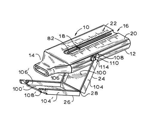
Referring initially to FIGS. 1 through 3, the portable peak
flow meter 10 of the present invention consists of a main body 12
in the general form of a hollow rectangular prism, coupled to a
mouthpiece 14 at a first end and having an exhaust at the opposed
second end 16. A flow rate indicator 18 extends through a slot in
the upper surface 20 of the body, which is provided with indicia
22 calibrated to indicate the flow rate shown by the indicator.
A pair of cover elements 24, 26, hinged together at 28, are pivotly
attached to the sides of the body at 30. In a first position,
shown in FIG. 1, the cover pieces enclose the mouthpiece 14, while
in the operating position~as shown in FIG. 3, the cover elements
24, 26 extend downwardly from the body 12 in a generally
perpendicular manner and provide an operating handle for the unit.
With reference to FIGS. 4 through 6, the body 12 may be formed
of upper and lower portions 32, 34, best seen in FIG. 5, which may
be joined together along a horizontal seam in an appropriate manner
to provide the body chamber. Interlocking elements may be provided
to allow the portions to be joined together without the need for
adhesive. As may be seen in FIG. 4, both upper and lower body
portions include the opposed side walls 36, 38 which, in
conjunction with top 40 on portion 32 and bottom 42 on portion 34
define a rectangular chamber through which the expired air passes.
Mounted within the chamber are interi~r walls 44, 46, each of
which has portions formed as a part of upper body and lower body
portions 32, 34. The interior walls divide the chamber into three
generally parallel passageways 54, 56 and 58 having a common
2~329
entrance port area at the right-hand end of the body. The inner
walls 44, 46 include, at their proximal ends, respective arcuate
portions 48, 50, the inwardly-directed ends of which define a
narrow entrance aperture 52 into the central chamber 54. The
arcuate portions 48, 50 also serve to smoothly divert the incoming
air flow not aligned with the entrance aperture 52 to the opposed
lateral passageways 56 and 58, defined by the side walls 36, 38 and
the respective adjacent inner walls 44, 46.
Mouthpiece 14 adjoins the first end of the body 12 and
includes a first portion 60 adapted and dimensioned to be held by
the lips of the user, coupled to flared portion 62 which mates at
its distal end with the first end of the body 12. As shown, the
body 12 may be provided with a peripheral shoulder 64 which mates
with a similar opposed shoulder 66 on the mouthpiece to connect the
body and mouthpiece together. Both the body and mouthpiece may be
formed of any appropriate material, such as styrene plastic. The
mouthpiece may be permanently joined to the body or may be
removable.
Mounted within central passageway 54 is piston 68, which the
expiratory flow impinges against to provide measurement of its flow
rate. As seen in FIGS. 4 and 5, piston 68 includes piston plate 70
positioned transversely to the passageway 54, and which provides
a flow barrier across the passageway. The plate is mounted to
collar 72, which has a bore therethrough through which support
rod 74 extends, permitting travel of the piston along the length
of the chamber. Support rod 74 is supported at is ends in notched
support blocks 76, 78, each of which is formed in two parts, as
elements of the upper and lower body portions 32, 34 as may be seen
in FIG. 5. Spring 80 has its first end affixed to the piston 68
and its second end affixed to the support block 76 at the entrance
to passageway 54 to provide an appropriate restoring force against
the force developed by the expiratory air against the piston plate
70.
6 2~88s29
In order to provide a visual indication of the maximum
displacement of the piston 68 as a result of expiratory flow, the
top 40 of the body is provided with a longitudinal slot 82
extending for a length corresponding to the travel of the piston
from its rest position to a displaced position resulting from the
maximum contemplated expiratory flow rate to be encountered.
As may be seen in FIGS. 6 and 8, the slot 82 may include a
lower neck portion 84 having parallel sides adjoining an upper,
generally semicircular portion 86. Extending through the slot is
the indicator 18, seen in FIG. 8, which includes a neck section 90
rectangular in cross-section adapted to be embraced by the neck
section of the slot. The neck 90 supports at its upper end an
indicator head 92 embraced by the hemispherical portion 86 of the
slot, the head bearing on its top surface a transversely directed,
generally rectangular pointer means 94 which, during travel, aligns
with the indicia 22 seen in FIG. 3 to indicate the flow rate.
Extending downwardly from the neck 90 is a widened base portion 96,
terminating in hemispherical end 98. The hemispherical end 98
rests upon support rod 74 and is engaged by the piston plate 70
whereby the indicator is moved leftwardIy as shown in FIGS. 4 and
5 in accordance with the maximum expiratory flow rate developed by
the user. As the flow rate decreases, the piston returns to the
right, the indicator remaining in its position of maximum
displacement from its initial, rightmost position to indicate the
maximum flow. Frictional forces between the indicator and the top
wall and/or the support rod 74 retain the indicator in position
upon retraction of the piston. Spring means 88 encircling portion
96, provides an expansion force between the hemispheric end 98, top
wall 40 and support rod to enhance the frictional contact to insure
that the indicator does not inadvertently change position.
The cover pieces 24, 26 provide protection for the mouthpiece
14 of the device when not in use and, when pivoted to the position
as shown in FIG. 3, both expose the mouthpiece for use and serve
7 20~329
as an operating handle for the unit. As seen in FIGS. 1-3, first
cover piece 24 includes a bottom panel 100 surrounded by upstanding
end wall 102 and opposed side walls 104, 106. A pair of arms 108
are formed as extensions to the side walls 104, 106, each arm
including a generally semicircular shoulder portion 110 of reduced
thickness fully surrounding transverse bore 112, as detailed in
FIGS. 9A and 9B. Posts 114 extend from the body side walls 36,
38, and serve as axles through the bores 112, allowing the handle
unit to pivot thereabout. The portion of the post 114 extending
beyond the bore may be widened or otherwise deformed to prevent
removal of the handle.
The second cover piece 26 is of generally similar
construction, including top panel 100', end wall 102' and side
walls 104', 106'. Its arm portions 108' are each provided with a
semicircular recess 116 on the inner face thereof to accept the
semicircular shoulder 110 of the arm 108, and further includes
semicircular transverse bore 118 to accommodate the posts 114.
The semicircular shoulders 110 of the arms 108 may further
include a latch shoulder 120, which engages with a complimentary
shoulder 122 formed into the surface of the semicircular recess 116
in the arms 108', such that the cover elements may interengage and
lock, both in the closed position as shown in FIG. 1, as well as
in the open and operative position as shown in FIG. 3. The cover
portions 24, 26 may be formed from a unitary piece of material,
typically polypropylene, and are joined at the tops of their end
walls 102, 102' by integral self-hinge element 28. It is to be
further appreciated that the distance "d" between the ends 124,
124' of the bottom and top panels 100, 100', respectively, and the
center of the transverse bores 112, 118 in the arms 108, 108' is
equal to the height above the bottom 42 of the body for the axis
of posts 114, such that in the open position, as shown in FIG. 3,
the handle assumes the perpendicular position, whereby the body
2~88 j ~9
10 is generally retained in position by the ends 124, 124' of the
cover panels.
The peak flow meter is normally disposed in the closed
condition shown in FIG. l, with the cover pieces 24, 26 engaged
with each other about the mouthpiece of the unit. In such a
condition, the unit may be placed in the pocket, in a handbag or
attache case, or the like, with the mouthpiece being covered and
protected from inadvertent contact with surrounding objects. When
it becomes necessary to operate the device, the cover elements are
separated and pivoted about the body, re-engaging in the
perpendicular position as shown in FIG. ~. The piston is in the
rest position as depicted in FIG. 4. The indicator is gently slid
to the right such that the hemispheric protrusion 98 is in gentle
contact with the piston. The user then places the mouthpiece in
his or her mouth and exhales through the unit in the manner taught
by the prescribing professional. The expiratory breadth enters
the body of the unit, a substantial portion thereof being diverted
by the curved end portions 48, 50 of the inner walls 44 and 46 to
pass the piston through the lateral passageways 56, 58. A portion
of the air enters the central air passageway 54, where it impinges
against the piston plate 70, driving the piston plate to the left
as shown in phantom in FIG. 4 against the restoring force of the
spring 80. Slot 82 allows for dissipation of the breadth portion
impinging against the piston without substantial diminution of the
force generated thereby.
Maximum travel of the piston corresponds to the maximum flow
rate and resultant force. As the flow rate decreases and
terminates, the piston returns to the rest position. During piston
travel, however, the indicator 18 is driven to the left, remaining
in the position corresponding to the maximum flow rate. This
maximum flow rate can be read off the indicia 22 on the top surface
of the unit, the flow rate to be used for reporting or medication
dispensation by the patient as instructed. The indicator then may
208832~
be reset to the rightmost position, the handles being separated
from the operative position to be refolded about the mouthpiece of
the unit to permit storage.
In general, for a central passageway of cross-sectional area
of 1.125 inches x .52 inches (2.86 cm x 1.32 cm) and having an
entranceway of .375 inches by .52 inches (.9S cm x 1.32 cm), a
spring formed of .008 inch (.0020 cm) diameter type 302 stainless
steel having a spring constant of .01341b./inch (2.35 x 10³ dyne/cm)
has been found to allow measurement across the range of flow rates
typically experienced with a piston travel of about 3.8 inches
(9.65 cm).
It is to be recognized that modifications and adaptations of
the present invention as set forth herein are possible without
departing from the spirit or scope of the invention.