Note: Descriptions are shown in the official language in which they were submitted.
CA 02088494 1998-04-1~
-
DEVICE FOR RETAINING A TYRE ON A VEHICLE WHEEL
Attempts have earlier been made, partlcularly in
- connection with cross-country vehicles, to design rim
constructions which permit running with the tyre under
severe loading or heavy duty conditions, and also running
with the tyre in a deflated state, commonly referred to as
run-flat driving. Examples of known constructions are
given in SE-B-317,003, SE-B-362,219, DE-1,505,080, US-A-
2,028,601, US-A-2,409,666, US-A-4,151,870, US-A-3,664,405,
US-A-3,669,174, US-A-4,572,265 and SE-B-418,481 (= US-A-
4,016,917).
The construction disclosed in SE-B-418,481 relies on
jaws or bead clamps which are elongate and which extend,
when in their operative position, in the axial direction
of the vehicle wheel to press the tyre beads against the
rim flanges. The bead clamps are retained in place by a
clamping bolt passing through the rim bottom and mechanic-
ally pressing the bead clamps against the rim bottom,
whereby to obtain a stable and strong engagement. These
prior-art bead clamps have proved most useful and reliable
for many types of vehicle tyres.
It has however been found that these bead clamps may
sometimes tend to rotate about the clamping bolt, particu-
larly under heavy duty conditlons and especially whenusing tyres having a large axial width, particularly low-
profile tyres for forest machines and other cross-country
vehicles. In fact, the purpose of the bead clamps is to
mechanically fix the tyre on the rim to prevent it from
slipping thereon, also in the case of low air pressure.
Another purpose of the bead clamps is to prevent air
lea~age between the tyre beads and the rim flanges as a
result of the tyre beads coming loose from the rim flanges
when the tyre is subJected to high lateral stresses. If
the bead clamps should rotate about the clamping bolt, the
intended fixation of the tyre would be undone.
W O 92/22437 PC~r/SE92/00395
208~49~ 2
One object of the present invention therefore is to
provide an arrangement in vehicle wheels which reduces or
completely obviates the risk of unintentional rotation of
the bead clamps.
Another object of the invention is to provide an
arrangement in vehicle wheels which increases the capacity
of the vehicle wheel to take up very high lateral forces.
Such lateral forces occur especially in wheels for cross-
country forest ~ch;nes.
Yet another object of the invention is to provide an
arrangement in vehicle wheels which increases the ability
of the wheel to ensure air tightness in the areas where
the tyre beads engage the rim flanges and the tyre bead
seat, also at low air pressures in tubeless tyre designs.
A further object of the invention is to improve the
device disclosed in SE-B-418,481 (= US-A-4,016,917) and to
make it easier to mount and correctly position the bead
clamps on the vehicle wheel.
These and other objects of the invention are achieved
by means of an arrangement in vehicle wheels as defined in
claim 1. The dependent claims recite particularly pre-
ferred embodiments of the invention.
In the invention, use is made of a number of jaws or
bead clamps for securing a pneumatic tyre on the rim.
These jaws or bead clamps are elongate and rotatable, and
are disposed, when in the operative position, with their
longitudinal axis in the axial direction of the vehicle
wheel. The jaws or bead clamps are pressed both against
the tyre beads in order to apply these against the rim
flanges, and against the rim bottom in order to stabilise
the jaws or bead clamps and to eliminate or substantially
reduce the risk of tilting of the jaws or bead clamps
because of heavy impacts in the circumferential direction
of the vehicle wheel. The jaws or bead clamps are retained
by means of a clamping bolt which is connected to the jaws
or bead clamps and extends through a hole in the rim
bottom. The clamping bolt is disposed at a location bet-
W092/22437 2 0 8 ~ ~ 9 I PCT/SE92/00395
ween the ends of the jaws or bead clamps, preferablyfairly centrally so as to enable requisite pivotal move-
ment of both ends of the jaw or bead clamp when mounting
and dismounting the tyre. To prevent unintentional rota-
tion of the jaws or bead clamps about their clampingbolts, the rim bottom has, in accordance with the inven-
tion, been provided or formed with fixing lugs, against
which the jaws or bead clamps abut when mounted.
To prevent unintentional pivotal movement of the jaws
or bead clamps, it suffices that each bead clamp or jaw is
associated with two fixing lugs or ridges. These two fix-
ing lugs or ridges may be located on the same side of the
associated jaw or bead clamp, however offset in different
directions away from the clamping bolt of the jaw or bead
clamp. Another option is to use two fixing lugs, one on
each side of the jaw or bead clamp at a certain distance
from the clamping bolt. For optimum results and for
achieving a highly reliable mounting, it is preferred to
use four fixing lugs, arranged pairwise on each side of
the jaw or bead clamp, the two pairs being disposed on
each side of the clamping bolt and at a distance there-
from.
Within the scope of the invention, it is also poss-
ible to use fixing lugs which are elongate in the axial
direction of the vehicle wheel so as to define a valley
between them, in which the jaw or bead clamp is disposed
when mounted.
To ensure that the jaws or bead clamps are conveni-
ently guided into place when being mounted, the top side
of the fixing lugs is preferably rGunded or bevelled. This
can easily be achieved if using fixing lugs formed of
metal rods having round or semicircular cross-section,
which are welded to the rim bottom.
When the bead clamps or jaws are to be used in a
tubeless tyre construction, air tightness is ensured where
the clamping bolt passes through the rim bottom by arrang-
ing a suitable seal of elastomeric material or other seal-
wo 92,2243,2 ~ 8 ~ 4 9 ~ PCT/SE92/~395
ing material around the clamping bolt between the rimbottom and the jaw or bead clamp.
In the invention, use is preferably made of jaws or
bead clamps having a fixed length. Within the scope of the
invention, it is however also possible to use jaws or bead
clamps of expandable type according to the disclosure of
SE-B-418,481. This publication therefore is included in
this description by reference.
The invention will be described in more detail here-
inbelow in a currently preferred embodiment. Fig. 1 is aradial section of a vehicle wheel according to the inven-
tion. Fig. 2 is a section taken along the line II-II in
Fig. 1. Fig. 3 is a perspective view showing parts of a
rim and a bead clamp mounted thereon.
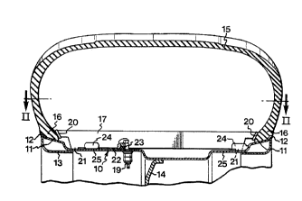
Fig. 1 shows a rim 10 having reinforced rim seats 11
and rim flanges 12. The reinforcement consists of a weld-
ed angle section 13. The rim has a rim disc or spoke
structure 14. A vehicle tyre 15 is mounted on the rim,
such that the tyre beads 16 engage the rim seats 11 and
also the rim flanges 12. The tyre beads are pressed
firmly against the rim flanges 12 by means of bead clamps
17 which are arranged in spaced-apart relationship around
the rim. In ordinary cases, e.g. six or eight evenly dis-
tributed bead clamps can be used. Only one of the clamps
is however shown in the drawings.
The bead clamp shown in the drawings consists of a
welded box girder of sheet metal with a clamping bolt 19
fastened thereon. At the ends of the bead clamp, there
are provided clamping surfaces 20 which are pressed
against the tyre beads 16, and also abutment surfaces 21
which are pressed against the rim bottom. The bead clamps
also have a sealing surface 22 which is pressed against a
suitable rubber or plastic gasket 23 engaging the rim
bottom so as to ensure air tightness around the clamping
bolts 19.
W O 92/22437 2 0 ~ 8 ~1 ~ ~ PC~r/SE92/00395
According to the invention, the rim 10 has a number
of fixing lugs or ridges 24 which in the illustrated
embodiment consist of short round pieces of steel, also
having rounded ends and being welded to the rim bottom.
The lugs 24 are arranged pairwise on both sides of the
bead clamp 17 to prevent it from being unintentionally
rotated about the clamping bolt when sub;ected to high
stresses. In this embodiment, one pair of lugs has been
disposed adjacent the rim seat 11 while the other pair has
been disposed some distance away from the opposite rim
seat 11 to make room for one tyre bead when mounting and
dismounting the tyre.
One way of mounting the tyre 15 on the rim 10 is to
first force one of the tyre beads over one of the rim
flanges 12, whereupon the bead clamps are passed into the
tyre and into their fixing holes, the bead clamps 17 being
so turned that the longit~ A 1 direction of the bead
clamps roughly coincide with the plane of rotation of the
rim. The bead clamps are thus swung about 60-90~ with
respect to the position shown in the drawings. After
applying the nut on the fixing bolt projecting through the
rim bottom, the bead clamp is pressed as far into the tyre
as possible while maintAin;ng this orientation. The other
tyre bead is thereafter forced over the rim flange, and
the tyre is inflated, e.g. to about 500 kPa. The bead
clamps are thereafter swung to the position shown in the
drawings and pulled down against the rim by tightening the
nut. By the provision of the fixing lugs 24, the bead
clamp is forcedly guided into its intended operative posi-
tion. When the nut has been completely tightened, the tyre
beads 16 will be sealingly pressed against the rim flanges
12 and the rim seats 11 at the same time as the gasket 23
is compressed and the abutment surfaces 21 are urged into
firm mechanical engagement with the rim bottom 25.
As earlier mentioned, the bead clamps may be expand-
able in the longitudinal direction, as stated in SE-B-
418,481. The same advantages are obtained in this case by
the use of the fixing lugs 24.
W O 92/224 ~ 0 8 8 ~ 9 ~ PC~r/SE92/00395
In the event of a puncture, the bead clamps, as in
the device according to SE-B-418,481, will maintain the
tyre beads clamped against the rim seats and the rim
flanges with a force replacing the clamping force exerted
by the air pressure. When using extreme low-profile tyres,
as on forest machines, this clamping force brought about
by the bead clamps may also supplement the clamping action
of the air pressure, so as to give the tyre a considerably
improved capacity to withstand high lateral loads as a
result of the lugs 24 preventing the bead clamps from
turning about the clamping bolts.
Moreover, the clamping of the tyre beads prevents the
tyre from slipping on the rim, which in turn means that
the tyre can transmit driving and braking forces also when
punctured. In this manner, the mobility of the vehicle
both under cross-country conditions and on roads will
largely remain unaltered, also in the event of a puncture.
By the design of the bead clamps, which thus are not to be
compared to the known run-flat rings provided on the inner
side of the rim, it is possible to achieve sufficient
clamping to permit running the tyres at extremely low air
pressures in cases where, for example, additional carrying
capacity or additional traction is required for driving on
very loose ground. Moreover, the clamps permit using tube-
less tyres also under cross-country conditions, without
the risk of slow leaks because of foreign matter penetrat-
ing in between the tyre wall and the rim flange. A major
advantage gained by the clamp beads being designed to
mechanically abut both on the rim bottom and on the tyre
beads is that the bead clamps are stabilised and prevented
from breaking or tilting or being rotated as a result of
the substantial stresses which arise in run-flat driving.
If, moreover, use is made of the bead clamps in com-
bination with a lubricant, it is possible to run punctured
tyres over long distances. If the damage to the tyre is
only caused by pointed weapons or small-bore arms, it is
in fact not necessary to dismount the tyre from the rim
W092/22437 2 ~ 9 4 PCT/SE92/~395
but simply to plug the hole, whereupon the tyre is inflat-
ed and again becsm~s functional.
In fact, the bead clamps in the construction accord-
ing to the invention are so effective that the tyre is
retained on the rim even if it were to be blown up by
running over a landmine. Since the tyre remains on the rim
despite such serious damage, it is possible to continue
using the damaged tyre for transmitting driving power and
braking forces and imparting carrying capacity to the
wheel. Of course, a damaged tyre retained of the rim is
better than the rim alone.
Another substantial advantage of the construction
according to the invention is that a split rim need not be
used for mounting the bead clamps, i.e. these fit both
flat-base rims and drop-centre rims.