Language selection

Search

Patent 2088638 Summary

Third-party information liability

Some of the information on this Web page has been provided by external sources. The Government of Canada is not responsible for the accuracy, reliability or currency of the information supplied by external sources. Users wishing to rely upon this information should consult directly with the source of the information. Content provided by external sources is not subject to official languages, privacy and accessibility requirements.

Claims and Abstract availability

Any discrepancies in the text and image of the Claims and Abstract are due to differing posting times. Text of the Claims and Abstract are posted:

  • At the time the application is open to public inspection;
  • At the time of issue of the patent (grant).
(12) Patent: (11) CA 2088638
(54) English Title: TUMBLE GRINDER WITH SCREEN PORTION
(54) French Title: BROYEUR A CULBUTAGE AVEC GRILLAGE SEPARATEUR
Status: Deemed expired
Bibliographic Data
(51) International Patent Classification (IPC):
  • B02C 18/06 (2006.01)
  • B02C 17/02 (2006.01)
  • B02C 21/02 (2006.01)
  • B07B 1/22 (2006.01)
(72) Inventors :
  • DORSCHT, JOHN P. (Canada)
  • HOGAN, PATRICK J. (Canada)
(73) Owners :
  • ASTEC INDUSTRIES, INC. (United States of America)
(71) Applicants :
  • DORSCHT, JOHN P. (Canada)
  • HOGAN, PATRICK J. (Canada)
(74) Agent: BORDEN LADNER GERVAIS LLP
(74) Associate agent:
(45) Issued: 1997-10-14
(22) Filed Date: 1993-02-02
(41) Open to Public Inspection: 1993-08-04
Examination requested: 1993-02-02
Availability of licence: N/A
(25) Language of filing: English

Patent Cooperation Treaty (PCT): No

(30) Application Priority Data:
Application No. Country/Territory Date
07/829,317 United States of America 1992-02-03

Abstracts

English Abstract


A tumble grinder is disclosed in which material
which is already sufficiently small in size, primarily being
abrasive aggregate or earthen material, may be discharged from
the receptacle to bypass the comminution apparatus and thus
substantially reduce wear thereto. A portion of the
cylindrical wall of the receptacle is provided with
classifying openings, for example by providing a screened
opening as a band around the receptacle. The classifying
openings permit material which is already smaller than the
size of the openings to fall therethrough, thereby bypassing
the comminution apparatus. Preferably, a conveyor is
positioned beneath the receptacle, to catch and discharge the
material which falls through the screen or other classifying
openings to a pile located away from the receptacle.
Sidewalls positioned on either side of the receptacle stop any
material which is flung out to the side, and redirect it down
onto the conveyer. The apparatus may be advantageously
mounted on a trailer, for towing from site to site. In such
an arrangement, it is advantageous to provide an integrated,
transportable system, in which the receptacle is moveable
between an operating position and a transportation position.


French Abstract

Broyeur à culbutage conçu pour laisser passer les matériaux (principalement des granulats abrasifs ou de la terre) dont les dimensions sont déjà suffisamment réduites, ce qui permet de diminuer l'usure de l'appareil. Le récipient comporte des ouvertures classeuses disposées en bande sur une portion de sa paroi cylindrique, par lesquelles passent les matériaux dont les dimensions sont inférieures au diamètre de ces dernières, contournant ainsi le dispositif de broyage. Un convoyeur est de préférence placé sous le récipient pour recevoir les particules de matériaux ainsi rejetées, et pour les mettre en tas, à l'écart du récipient. Des parois latérales placées de chaque côté du récipient arrêtent toutes les particules qui sont projetées à l'extérieur et les guident vers le convoyeur. Il serait préférable de monter l'appareil sur une remorque pour pouvoir le déplacer d'un endroit à l'autre. Dans ce cas, il faudrait prévoir un système transportable intégré, à récipient mobile à deux positions, c'est-à-dire position de fonctionnement et position de transport.

Claims

Note: Claims are shown in the official language in which they were submitted.

THE EMBODIMENTS OF THE INVENTION IN WHICH AN EXCLUSIVE
PROPERTY OR PRIVILEGE IS CLAIMED ARE DEFINED AS FOLLOWS:


1. Tumble grinding apparatus, comprising:
a floor angled away from the horizontal, having an
opening therethrough communicating with comminution means, and
a cylindrical wall positioned against and generally above said
floor with its axis at a right angle thereto to define an
angled receptacle for receiving material to be comminuted by
said comminution means, said wall being rotatable with respect
to said floor about said axis, and
means for rotating said cylindrical wall to cause
tumbling of said material to be comminuted;
whare said cylindrical wall has classifying openings
therethrough around a substantial portion thereof, whereby
material small enough to pass through said classifying
openings may fall from said receptacle through said wall
instead of being routed to said comminution means.


2. Apparatus as recited in claim 1, further comprising
means positioned beneath said classifying opening portion for
catching said material which falls through said classifying
openings and for conveying said material away from beneath
said classifying openings.


3. Apparatus as recited in claim 2, further comprising
stationary sidewalls positioned on either side of said

receptacle opposite said classifying openings, whereby


material which is flung out to one side or the other through
said classifying openings is stopped and redirected to drop
down onto said means for catching and conveying said material
from beneath said classifying openings.


4. Apparatus as recited in claim 1, where said
classifying openings are provided by virtue of a substantially
open band around said wall, said substantially open band
having a screen mounted therearound, covering said
substantially open area.


5. Apparatus as recited in claim 2, where said
classifying openings are provided by virtue of a substantially
open band around said wall, said substantially open band
having a screen mounted therearound, covering said
substantially open area.


6. Apparatus as recited in claim 3, where said
classifying openings are provided by virtue of a substantially
open band around said wall, said substantially open band
having a screen mounted therearound, covering said
substantially open area.


7. Apparatus as recited in claim 4, where said
substantially open band is formed by virtue of upper and lower
circumferential channel members on either side of said band, a
plurality of spaced-apart bars secured between said channel
members, screen material overlaid on the outside of said bars,


and clamping plates outside said screen material fastened to
at least some of said bars to secure said screen material
against said bars.


8. Apparatus as recited in claim 5, where said
substantially open band is formed by virtue of upper and lower
circumferential channel members on either side of said band, a
plurality of spaced-apart bars secured between said channel
members, screen material overlaid on the outside of said bars,
and clamping plates outside said screen material fastened to
at least some of said bars to secure said screen material
against said bars.


9. Apparatus as recited in claim 6, where said
substantially open band is formed by virtue of upper and lower
circumferential channel members on either side of said band, a
plurality of spaced-apart bars secured between said channel
members, screen material overlaid on the outside of said bars,
and clamping plates outside said screen material fastened to
at least some of said bars to secure said screen material
against said bars.


10. Apparatus as recited in claim 1, mounted on a
trailer, where said receptacle is pivotally mounted on said
trailer for movement between an angled operating position and
a generally horizontal transportation position.
11

11. Apparatus as recited in claim 2, mounted on a
trailer, where said receptacle is pivotally mounted on said
trailer for movement between an angled operating position and
a generally horizontal transportation position.


12. Apparatus as recited in claim 3, mounted on a
trailer, where said receptacle is pivotally mounted on said
trailer for movement between an angled operating position and
a generally horizontal transportation position.


13. Apparatus as recited in claim 4, mounted on a
trailer, where said receptacle is pivotally mounted on said
trailer for movement between an angled operating position and
a generally horizontal transportation position.


14. Apparatus as recited in claim 5, mounted on a
trailer, where said receptacle is pivotally mounted on said
trailer for movement between an angled operating position and
a generally horizontal transportation position.


15. Apparatus as recited in claim 6, mounted on a
trailer, where said receptacle is pivotally mounted on said
trailer for movement between an angled operating position and
a generally horizontal transportation position.


16. Apparatus as recited in claim 7, mounted on a
trailer, where said receptacle is pivotally mounted on said
12


trailer for movement between an angled operating position and
a generally horizontal transportation position.

17. Apparatus as recited in claim 8, mounted on a
trailer, where said receptacle is pivotally mounted on said
trailer ~or movement between an angled operating position and
a generally horizontal transportation position.


18. Apparatus as recited in claim-9, mounted on a
trailer, where said receptacle is pivotally mounted on said
trailer for movement between an angled operating position and
a generally horizontal transportation position.


13

Description

Note: Descriptions are shown in the official language in which they were submitted.


2 ~

This invention relates to comminution apparatus, and
in particular to tub grinders of the type having a receptacle
defined by a stationary angled floor and a rotating
cylindrical wall. The wall is positioned adjacent to the
floor with its axis at right angle to the floor and at a
substantial angle away from the vertical. An aperture in the
floor leads to a hammer mill or other comminution means.
~ ub grinders are well known, and are commonly used
in applications such as comminuting yard waste, branches,
shrubs, stumps, logs, forage crops, wooden pallets, railroad
ties, sla~wood, paper, cardboard, and many other materials.
In such grinders, a hammer mill or other comminution means is
located beneath a receptacle, with the h~ ?rs rotating about
a horizontal axis with the hammers projecting up slightly into
the receptacle, through an aperture provided in the stationary
bottom of the receptacle. Rotating the wall of the receptacle
feeds the material past the area of the hammers. The hammers
pull the material through a cylindrical housing, pulv~rizing
it and then shooting it out an exhaust, usually via a simple
discharge chute.
The receptacles may be mounted with their main axis
vertically oriented, in which case they are commonly referred
to as tub grinders, or with the main axis at a substantial
angle away from the vertical, in which case they may be
referred to as tumble grinders.
Although hammer mills are commonly used in such
grinders, other comminution apparatus is also common, such as
flails or grinding rollers.


2 ~ 8
In any tub or tumble grinder, much of the debris
being dumped into khe receptacle for processing may already be
sufficiently small to not require further comminution. In the
case of yard waste, for example, the debris may include a
large volume of abrasive aggregate including earth, sand,
small stones and other abrasive materials which significantly
reduce the life of the hammers or other wearing components of
the comminution apparatus.
Also, it is frequently desirable to regrind material
1~ which has already been through the tumble grinder once.
Maturally, a substantial portion of such reprocessed material
has already been reduced to a desirable size. However, once
debris is dumped into the receptacle, all of it must exit
through the hammer mill or other comminution apparatus.
Thus, in a conventional grinder, it is common to
process much more material through the hammer mill or other
comminution apparatu~ than may really be necessary. This is
certainly not a desirable characteristic, since it reduces the
rate at which material may be processed, and places
unnecessary wear on the hammers or other comminution means.
It is an object of the invention to provide an
improved tub grinder, in which material which is already
sufficiently small in size may be discharged from the
receptacle without passing through the hammer mill or other
comminution means, thereby significantly reducing wear to the
comminution means, especially since much of such small
material is quite abrasive.


. ~
- :: ... .
. .

.

2~8~3~
In the invention, the receptacle is mounted at a
substantial angle, e.g. typically in the range of 30 to 60
degrees from the vertical. A portion of the cylindrical wall
of the receptacle is provided with classification openings,
for example by providing a screen opening as a band around the
receptacle. The classifying openings permit material which is
already ~maller than the size of the openings to fall
therethrough, thereby bypassing the comminuti~n apparatus and
significantly reducing wear on the comminution apparatus.
In the preferred embodiment, the material which
falls through the screen or other classifying openings falls
onto a conveyor. Sidewalls are positioned on either side of
the receptacle, to stop any material which flies out to one
side or the other, to redirect it downwardly onto the
conveyor.
The apparatus may be advantageously mounted on a
trailer, for towing from site to site. In such an
arrangement, it is advantageous to provide an integrated,
t ansportable system, in which the receptacle is moveable
between an operating position and a transportation position.
Further features of the invention will be described
or will become apparent in the course of the following
detailed description.
In order that the invention may be more clearly
understood, the preferred embodiment thereof will now be
described in detail by way of example, with reference to the ~.
accompanying drawings, in which:


:. .. . ..

2~$~ 8
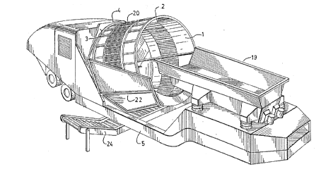
Fig. 1 is a perspective view of the apparatus
mounted on a trailer;
Fig. 2 is a side elevation view of the apparatus;
Fig. 3 is a side elevation view of the apparatus,
shown in the transportation position, with the ~perating
position shown in ghosted linesi
Fig. 4 is a side elevation of the apparatus, shown
in section;
Fig. 5 is a perspective view of the receptacle '
support and sidewalls;
Fig. 6 is a perspective view of the receptacle, the
receptacle support, and the sidewalls;
Fig. 7 is a cross-section of the receptacle wall;
Fig. 8 is a cross-section of the receptacle wall at
right angles to the cros~-section of Fig. 7 and
Fig. 9 is a cross-sectional elevation view of the
receptacle.
As illustrated in the ~ccompanying drawings, the
apparatus includes a receptacle 1 defined by a cylindrical
wall 2 positione~ with its axis at a right angle to a
stationary angled floor 3 mounted across a portion of a
support assembly 4. The support assembly is mounted on a
trailer 5, and is pivotable about pivot pins 6 between an
operating position and a transportation position, as seen best
in Fig. 3.
As seen best in Fig. 5, the support assembly 4
consists of a receptacle support fram~ 7 welded to the floor
support frame 8. Receptacle support rollers are mounted on


, . : : ~ : ,, . . : . . ; .

the support assembly, including upper and lower side rollers 9
and 10 respectively ttwo of each, i.e. one on each side), and
four base rollers 11.
A hammer mill 12 is positioned with its hammers 13
projecting up through the floor of the receptacle in
conventional fashion. The hammer mill is powered by a diesel
engine 14. The receptacle wall is rotated in conventional
fashion via a hydraulic motor 15 which drives a receptacle
drive chain 16. The hammer mill shoots the material out at
high velocity into a discharge chute 17, which may include a
conveyor 18.
An optional orienting hopper 19 may also be mounted
on the trailer, which serves to feed material into the
receptacle. Material is dumped into the hopper, and is
vibrated or conveyed from the hopper into the receptacle.
In prior art receptacles, the wall of the receptacle
is solid. In the present invention, however, as mentioned
a~ove, classifying openings are provided such that material
which is already smaller than the opening size can fall
through the openings to thereby bypass the comminution
apparatus. In the preferred embodiment, the classifying
openings are prov:ided ~y a screen 20 in the form of a band
around a substantial central portion of the wall 2.
As seen best in Figs. 1 and 4, material which falls
through the screen falls onto a conveyor 24 which carries it
out to the side of the trailer. Panels secured to the support
frame 7 define sidewalls 22. The sidewalls are positioned on
either side of the receptacle, to stop any material which


.. .. ... .

~g~3~
flies out to one side or the other, to redirect it downwardly
onto the conveyor.
Referring to Figs. 5-7, the structure of the wall of
the receptacle will now be described in detail. ~he upper and
lower portions of the wall of the receptacle are defined by a
number of longitudinal ribs 26, having a skin 27 fastened to
the inside thereof to define the wall. The ribs terminate at
upper and lower channel members 28 and 29 respectively on
either side of the screened band 20. The upper channel member
28 receives one of the receptacle support rollers 9, while the
lower channel member 29 is the site of sprocket teeth (not
visible in the drawings) which are conventionally driven by
the chain 16 to rotate the receptacle.
Between the channel members 28 and 29, ninety bars
30 are welded (i.e. each 4 degrees apart). The screen
material 20 is overlaid on the outside of the b~rs. Clamping
plates 32 secure the scrsen against the bars at e~ery third
bar, being secured by nuts 34 and bolts 35. The bars 30
prevent large, heavy material (tree stumps, for example) from
damaging the screen, while allowing small material to freely
pass through.
The screen ~0 preferably has an opening size of
about one inch, but the opening size could be varied as
desired for the particular application. If desired, the
screen can be changed simply by removing the clamping plates
32.
It will be appreciated that the above description
relates to the preferred embodiment by way of example only.


~,: ,. :

~, . ' . ~ .

~ ~ g ~ r~ 3 ~

Many variations on the invention will be obvious to those
knowledgeable in the field, and such obvious variations are
within the scope of the invention as described and claimed,
whether or not expressly described.
For example, instead of using a screen, holes could
be provided in the normally solid wall of the receptacle,
although the thickness of the wall might have to be increased
to provide sufficient strength.
As another example, the receptacle could have an
open area as in the preferred embodiment described above, with
wires routed around thè receptacle across the opening, instead
of a screen. It would be feasible to use almost any
conventional classifying means which permits material of less
than a certain size to pass through while blocking large
material.


. .


, -; , : ;: .

Representative Drawing
A single figure which represents the drawing illustrating the invention.
Administrative Status

For a clearer understanding of the status of the application/patent presented on this page, the site Disclaimer , as well as the definitions for Patent , Administrative Status , Maintenance Fee  and Payment History  should be consulted.

Administrative Status

Title Date
Forecasted Issue Date 1997-10-14
(22) Filed 1993-02-02
Examination Requested 1993-02-02
(41) Open to Public Inspection 1993-08-04
(45) Issued 1997-10-14
Deemed Expired 2002-02-04

Abandonment History

There is no abandonment history.

Payment History

Fee Type Anniversary Year Due Date Amount Paid Paid Date
Application Fee $0.00 1993-02-02
Registration of a document - section 124 $0.00 1994-11-18
Maintenance Fee - Application - New Act 2 1995-02-02 $100.00 1995-01-20
Maintenance Fee - Application - New Act 3 1996-02-02 $100.00 1996-02-02
Maintenance Fee - Application - New Act 4 1997-02-03 $100.00 1997-01-20
Final Fee $300.00 1997-06-25
Maintenance Fee - Patent - New Act 5 1998-02-02 $150.00 1998-01-30
Registration of a document - section 124 $100.00 1999-01-11
Maintenance Fee - Patent - New Act 6 1999-02-02 $150.00 1999-01-21
Maintenance Fee - Patent - New Act 7 2000-02-02 $150.00 2000-01-26
Owners on Record

Note: Records showing the ownership history in alphabetical order.

Current Owners on Record
ASTEC INDUSTRIES, INC.
Past Owners on Record
DORSCHT, JOHN P.
HOGAN, PATRICK J.
PORTEC INC.
Past Owners that do not appear in the "Owners on Record" listing will appear in other documentation within the application.
Documents

To view selected files, please enter reCAPTCHA code :


To view images, click a link in the Document Description column. To download the documents, select one or more checkboxes in the first column and then click the "Download Selected in PDF format (Zip Archive)" or the "Download Selected as Single PDF" button.

List of published and non-published patent-specific documents on the CPD .

If you have any difficulty accessing content, you can call the Client Service Centre at 1-866-997-1936 or send them an e-mail at CIPO Client Service Centre.


Document
Description 
Date
(yyyy-mm-dd) 
Number of pages   Size of Image (KB) 
Cover Page 1994-02-26 1 31
Abstract 1994-02-26 1 43
Claims 1994-02-26 5 181
Drawings 1994-02-26 7 351
Description 1994-02-26 7 300
Cover Page 1997-10-03 1 88
Representative Drawing 1997-10-03 1 32
Assignment 1999-01-11 7 280
Prosecution Correspondence 1996-06-17 2 42
Examiner Requisition 1996-03-05 2 60
PCT Correspondence 1993-09-20 1 37
Office Letter 1993-11-22 1 33
PCT Correspondence 1997-06-25 1 44
PCT Correspondence 1994-07-20 1 31
Fees 1998-01-30 1 46
Correspondence 1999-03-02 1 1
Fees 1997-01-20 1 51
Fees 1996-02-02 1 40
Fees 1995-01-20 2 80