Note: Descriptions are shown in the official language in which they were submitted.
Dividella AG, CH-9472 Grabs PDL029/22.12.92
Packaging with Integrated Partitioning
The inventlon concerns packaging for the acceptance of
longitudinal objects according to the preamble of claim 1.
These types of packaging serve to accept ampules, bottles and
similar fragile items.
One problem exis-cs with similar, related packaging in each
case during formation of the final corrugation on both sides
of the packaging. If the final corrugation is dispensed with,
so that the final individual compartment is formed by a part
corrugation and by a parallel side wall, this final
individual compartment remains relatively unprotected against
knocks and shocks. For this reason, damage to the items
inserted into these outer individual compartments occurs
frequently. If, however, the outer individual compartment is
also closed off with a complete corrugation, the adhesion of
this corrugation to the support blank will require an
additional, horizontal material strip which protrudes to the
side, glued to an extended support blank. This widens the
packaging.
It is therefore a purpose of the invention to create
packaging of the type described in the introduction, with
which also the outer individual compartments are bordered and
protected by a full corrugation, the packaging being able to
be manufactured with the minimum use of material. According
to the invention, this purpose is fulfilled with packaging
which possesses the features as described in claim 1.
- 2 - ~ 73 1
The construction, in accordance with the invention, enables
the provision of a complete end corrugation on both sides,
without the need also for glueing the outer wall of these end
corrugations. The end corrugations are indeed completely
shaped, however they are merely held in position by the
parallel side walls. Since the parallel side walls are
integrated into the support blank, an additional material
blank can also be dispensed with. The corrugations are glued
directly onto the box base.
Preferably, the support blank also forms at least one
transverse side wall for the packaging, running transverse to
the corrugations, which is connected to the parallel side
walls. The support blank thus evidently has two functions. On
the one hand, it forms the actual packaging envelope, and on
the other hand serves the purpose of holding the corrugations
firmly in their predetermined position.
The packaging can be closeable with a separate slip lid. It
can, however, also be closeable with a folding lid which is
~ntegrally formed with the support blank. Shrink foils, paper
bands etc. would also be conceivable.
Particularly user friendly packaging arises if the folding
lid is hinged on a transverse side wall which is not directly
connected with the parallel side walls and which is able to
be pivoted out together with the folding lid. In this way the
front of the packaging can be fully uncovered, which
considerably facilitates the removal of items lying within.
In order to also avoid contamination of the interior of the
packaging, with this version as well, the end corrugations
and the individual compartments immediately bordering on
these can be protected by dust tabs which are formed
integrally with the parallel side walls. These dust tabs form
a tight closure in the corner areas. In order to avoid the
2 ~ ?
- 3
dust tabs pivoting outwards when the packaging is opened, it
is of particular advantage if these are connected to support
tabs which are formed integrally with the shaped blank and
which can be folded out from the plane of a corrugation
valley. In this way, the dust tabs can be rigidly glued, in
spite of the transverse side wall being able to be pivoted
out.
The corrugations can also, in a known way, possess differing
cross sections. With that, they can be formed approximately
prismatically, for example rectangularly. The cross section
of the corrugations can remain the same throughout their
entire length, or the corrugations can possess portions with
differing cross sections. This configuration is particularly
suited for the accommodation of items with varying cross
section throughout their longitudinal axis, or for the
accommodation of differently shaped items within the same
packaging.
Tamper indication on a version of the packaging with a
folding lid can be achieved in a particularly simple way if
the folding lid possesses an insert strip which is able to be
inserted between the faces of the corrugations and a
transverse side wall, and if a press-in tongue, which is
bordered by a perforation and which is connected to the
insert strip, is arranged on the transverse side wall, the
press-in tongue being able to be pressed in during initial
opening of the packaging and remain on the insert strip. The
connection between insert strip and press-in tongue ensues
during initial closure of the filled packaging. Opening of
the folding lid is obviously not possible without depression
of the perforation. This tamper indicating closure also
permits particularly easy manufacture on automatic filling
plants.
2 ~, ~, J 7
-- 4 --
With that, the insert strip can likewise possess a press-in
tongue which corresponds to the equivalent on the transverse
side wall, both the press-in tongues being firmly connected
with each other and being able to be pressed in together when
opening for the first time. The corrugations lying in the
area of the press-in tongues can, with that, possess a recess
providing space for release of the press-in tongues. The
faces of the corrugations obviously provide support for the
transverse side wall, with the exception of that point which
should be pressed in.
A particularly advantageous tamper indicating packaging can
be achieved if opening tabs, which are able to be torn open
for the removal of items, are arranged in the transverse side
wall on the face of each individual compartment. In this way,
each individual item can be fully enclosed by the packaging,
the individual removal of items being possible at the face.
An initial opening of a compartment is, with that, displayed
by tearing open of the opening tabs. The end corrugations
also make possible here an optimum utilisation of the basic
area. This embodiment of the packaging is particularly
suitable for the packaging of sterile disposal syringes.
The packaging can, with that, be closed with a firmly glued
folding lid which is integrally formed with the support blank
and which possesses a window tab which is able to be torn
open for the formation of a viewing port. The packaging
contents can in this way be checked, without the possibility
of removal of the individual items through the viewing port.
If the tearable opening tabs run to a point towards the upper
side edge of the transverse side wall, the opening tabs can
be relatively easily pressed out, respectively grasped hold
of.
- s -
Examples and embodiments of the invention are more closely
described in the following, illustrated by the drawings.
Namely:
igure 1 a plan view of packaging according to the
invention,
igure 2 a partial cross section through the
packaging according to figure 1,
igure 3 an enlarged detail of the representation
according to figure 2,
igure 4 a perspective representation of the
packaging according to figure 1 with slip
lid,
igure 5 a support blank of an alternative
embodiment of the packaging,
igure 6 a shaped blank for the support blank
according to figure 5,
igure 7 a perspective representation of the
finished packaging made from the blanks
according to figures 5 and 6,
igure 8 a plan view of a further embodiment with
differently shaped corrugations,
igure 9 a support blank of a further embodiment
of the packaging,
igure 10 a shaped blank for the support blank
according to figure 9,
2 ~ 3 IJ ~
-- 6 --
igure 11 a perspective representation of the
finished packaging made from the blanks
according to figures 9 and 10,
igure 12 a perspective representation of a further
embodiment with removal openings at the
face, before closure of the packaging,
and
igure 13 the packaging according to figure 12 with
closed lid and with an opened removal
opening.
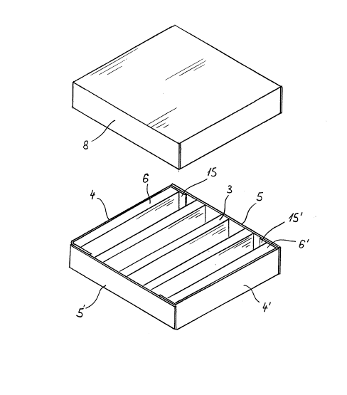
The figures 1 to 4 show an embodiment of the packaging with a
separate slip lid 8, which is in principle assembled in a
known way. A support blank 1 is glued to a shaped blank 2
which is deformed to be corrugated. The parallel side walls
4, 4' and the tranverse side walls 5, 5' are shaped
integrally from the support blank 1 and folded over from the
plane of the base through 90 degrees. Side tabs 15, 15, which
are glued to the transverse side walls 5, 5',' are arranged
on the parallel side walls 4, 4'. Naturally, these side tabs
could also be arranged on the transverse side walls.
The individual corrugations 3 form individual compartments 10
between one other, for introduction of the contents of the
packaging. The connection between the support blank 1 and the
shaped blank 2 occurs, with that, exclusively at the valleys
of the corrugations 13. An end corrugation 6, 6' is in each
case arranged directly next to the parallel side walls 4, 4'.
As can be seen particularly in figure 3, the outer wall 7 of
such a end corrugation makes close contact with the parallel
side wall 4. A firm connection of this outer wall with the
support blank 1 is not provided, and also not required.
Through that, no disruptive cavity occurs between the end
~ n ~ o ~ ~ '
~ ~ V ~i ~
-- 7 --
corrugation and the parallel side waLl, as would be necessary
when glueing the outer wall 7 to the support blank by means
of a protruding, horizontal material strip.
Figures 5 to 7 show an embodiment with a folding lid 9 which
is connected integrally with the support blank 1. The
configuration of this support blank can be seen in figure 5.
The support blank has a base 16, on the edges of which, once
again, the parallel side walls 4, 4' and the transverse side
walls 5, 5' connect. Side tabs 17 and 17' are arranged on
both sides of the transverse side wall 5. The parallel side
walls 4, 4' are integrally connected with the approximately
triangular dust tabs 11, 11'. The lid 21, with a facing strip
19 and with the side strips 22, 22', is directly connected to
the transverse side wall 5. Side tabs 18, 18' are arranged on
the side strips 22, 22'. A tamper indicating tongue 20 is die
cut into the facing strip 19, which can be ruptured in order
to open the lid. All individual sections are separated from
one another by folded edges 23 in a known way.
Figure 6 shows a shaped blank 2 in its extended position,
however somewhat shortened. The individual sections are
likewise separated from each other by folded edges 23. The
end corrugations 6, 6' extend over the entire width of the
packaging, whilst the other corrugations 3 are provided with
an inclination 24. Support tabs 12, 12' are shaped onto the
outermost corrugation valleys 13, 13'. The shaped blank is
closed off at the outside by both the outer walls 7, 7'.
Figure 7 shows the packaging, completely glued from the
material sections according to figures 5 and 6. On the
folding lid 9, the side tabs 18, 18'are glued to the facing
strip 19. The tamper indicating tongue 20, which is glued to
the transverse side wall 5 during initial closure, has been
ruptured.
- 8 - 2 ~ 3 i, ~ 1
Whilst the transverse side wall 5 remains in its upright
position through glueing of the side tabs 17, 17' with the
parallel side walls 4, 4', the transverse side wall 5' can be
completely pivoted out together with the folding lid 9. The
face becomes particularly easily accessible by this means.
The inclinations 24 on the corrugations 3 further facilitate
this accessibility. Since the transverse side wall 5' is not
connected with the parallel side walls 4, 4' to form a seal,
sealing of the corner area is effected by means of the dust
tabs 11, 11'. These are folded over from the plane of the
erected parallel side walls 4, 4' and connected with the
likewise erected support tabs 12, 12'. By this means, the
dust tabs remain in a rigid position, also when the
transverse side wall 5' is displaced.
Figure 8 shows an alternative embodiment of the packaging,
not only the end corrugations 6, 6' but also the corrugations
3 possessing differing cross sectional shapes. The end
corrugations have the sections 6a, 6b, 6c and the
corrugations have the sections 3a, 3b, 3c. From this,
individual compartments 10a, 10b of individual configuration
will arise. The individual sections of differing cross
sectional shape are formed by means of incisions which run
parallel to the transverse side walls 5, 5'.
Figures 9 to 11 show a further embodiment of the packaging
with folding lid and with a particularly advantageous tamper
indicating closure. The support blank 1 and the shaped blank
2 are, with that, designed somewhat differently to the blanks
according to figures 5 and 6. On the base 16, the parallel
side walls 4, 4' and the transverse side walls 5, 5' once
again connect to the sides. Both these transverse side walls
are both provided, at their sides, with the side tabs 26, 26'
and 27, 27', which are glued to the parallel side walls 4, 4'
on assembly. As opposed to the embodiment according to figure
- 9
5, the transverse side wall 5' can not be folded out. The lid
21 is hinged to the transverse side wall S', which is
provlded with an insert strip 25 on its free, guided side.
Dust tabs 28, 28' are provided for lateral sealing of the
lid.
A press-in tongue 30 is formed on the transverse side wall 5
by means of a half-moon shaped perforation 32. In a similar
way, a press-in tongue 29, which approximately corresponds to
the press-in tab 30 in shape and position, is also arranged
on the insert strip 25.
The shaped blank 2 according to figure 10 is shaped similarly
to that according to figure 6. The support tabs are, of
course, missing. As opposed to that, inclinations 24 are
likewise anticipated, indeed exclusively with the
corrugations 3 which lie between the end corrugations 6 and
6'. Those corrugations 3a and 3b, which lie in the area of
the press-in tongues 29, respectively 30 on the support
blank, are provided with a recess 31.
The completely assembled packaging is represented in figure
11, indeed shortly before initial closure of the filled
packaging. Here, a hotmelt 33 is applied to the press-in
tongue 29 on the insert strip 25, before the insert strip is
inserted between the transverse wall 5 and the face of the
corrugations. The hotmelt provides, with that, a firm
connection between the press-in tongue 29 and the inner side
of the press-in tongue 30. The corrugations 3a and 3b ~Figure
10), with the recesses 31, lie, in the case of closed
packaging, approximately just within the pivoting area of the
two interconnected press-in tongues 29 and 30.
For initial opening of the packaging, finger pressure is
exerted onto the press-in tongue 30, until the perforation 32
r~ ~ ~ r1 '
-- 10 --
breaks and both the tongues 29 and 30 pivot inwards. Now the
entire folding lid 9 can be lifted without effort and the
packaging subsequently permits further closure through re-
insertion of the insert strip 25.
A tamper indicating closure can also be realised in exactly
the same way on the packaging according to figure 7. There,
however, the facing strip 19 lies, with the press-in tongue,
outside on the transverse side wall 5.
The shapes for the press-in tab can be fully varied, and
thus, for example, also rectangular or trapezoidal.
In figures 12 and 13, a further embodiment of the packaging
is represented, with which removal of the contents does not
ensue from above but from the face. As with the previously
described packaging, all components are manufactured from a
support blank and a shaped blank. Dust tabs 28, 28' are
arranged on the parallel side walls 4, 4'. The side tabs 26
and 27 on the transverse side walls 5, 5' run parallel to the
corrugations 3 and 6. A folding lid 21 with an insert strip
25 is hinged onto the transverse side wall 5. During closure
of the packaging, this folding lid is firmly glued to the
insert strip and to the dust tabs 28 and 28', so that opening
is only possible through destruction of the packaging.
At the face of each individual compartment 10, an opening tab
34 is bordered by a perforation on the transverse side wall
5. As can be seen particularly in figure 13, these opening
tabs run to a tip towards the upper edge 37 of the transverse
side wall 5, the outermost tip even reaching into the area of
the lid 21. In the lid 21 itself a window tab 35 is likewise
bordered by perforations.
~, n ~
-- 11 --
In this packaging, for example sterile disposable syringes
can be packed. The sterility of these types of syringes is
only ensured as long as they are not handled in any way. In
the case of packaging which exposes the entire contents when
the lid is opened, there exists no guarantee that the entlre
packaging contents have remained untouched since initial
opening of the packaging. In the case of the embodiment in
question, for removal of an item lying within one individual
compartment 10, the corresponding opening tab 34 must be torn
open. The tips 39 of these tabs protrude slightly above the
upper edge 37 of the transverse side wall 5, and can be
relatively easily grasped hold of. By means of the opening 38
occurring in this way, the item can be removed. Evidentally,
in this way it will be ensured that the items in the still
closed individual compartments have remained untouched since
filling.
In order to check whether the packaging in fact actually
contains the correct contents, the window tab 35 can be torn
open and folded back, so that a viewing port 36 is formed
which does not fully reveal the individual compartments 10.
The items, thus for example the disposable syringes, can be
merely observed through the viewing port 36, but not removed.
Naturallyr the window tab 35 could also possess another
configuration than the triangular one shown here. The end
corrugations 6 ensure here, too, good lateral protection of
the outermost individual compartments 10. In spite of this,
the basic area of the packaging is optimally exploited and
the intermediate space between the outermost openings 38 and
the parallel side walls 4, respectively 4', is not larger
than the intermediate space between the individual openings
38.
Inasmuch as the invention is subject to modifications and
variations, the foregoing description and accompanying
- 12 -
drawings should not be regarded as limiting the invention,
which is defined by the following claims and various
comkinations thereof: