Note: Descriptions are shown in the official language in which they were submitted.
2osssz~
BACKGROUND OF THE INVENTION
The field of the invention relates to medical
instruments and more specifically to a cannula for use
with laparoscopic instruments to permit the passage of
laparascopic instruments through the cannula while
maintaining a seal around the instruments.
The use of cannulas in laparoscopic surgery is
well known. In laparoscopic surgery an incision is
made by means of a trocar and the abdomen is filled
with carbon dioxide gas. The cannula which maintains
the incision open to receive surgical instruments must
be kept closed to prevent the escape of the gas. Many
prior art cannulas utilize a trapdoor within ,the
i
housing of the cannula with the trapdoor being spY~ing
pressed to a closed position. The trapdoor opens when
an instrument is passed through the cannula. However,
quite frequently the laparoscopic instrument has a
curved tip or other structure which will catch on the
trapdoor and thus prevents the removal of the
instrument from the cannula. Cannulas of this type
are shown in the Moll et al patent 4,654,030 and the
Deniega et al patent 5,066,288.
Prior art cannulas are designed with flexible
seals to permit passage of instruments through the
cannula without permitting gas within the abdominal
cavity from leaking through the cannula. However,
2
CA 02088827 2003-08-07
such seals are generally designed for a single size of
instrument and when instruments of varying diameters are
used, the seals are ineffective and permit the escape of
gas from the abdominal cavity. The present invention
overcomes the above-noted disadvantages of prior art
cannulas.
SUMMARY OF THE INVENTION
The present invention overcomes the disadvantages of
prior art cannulas by providing a cannula for use with
laparoscopic instruments comprising a housing having a
bottom wall, top wall and sidewalk, said housing having
a passageway extending through the top and bottom walls,
a hollow tube extending from the bottom wall of the
housing, a pair of rollers disposed within the housing,
means mounting said rollers to urge the rollers together
so as to close the passageway within said housing, said
means permitting said rollers to separate and open the
passageway when a laparoscopic instrument is passed into
the passageway.
The cannula may have a pair of spring pressed
rollers which are urged to a position wherein the rollers
block off the passageway within the cannula to prevent
gas within the abdominal cavity from escaping to
CA 02088827 2003-08-07
atmosphere.
Preferably, a slidable plate is mounted on the
housing with the slidable plate having a series of
variable sized openings therein with each of the openings
having slitted flexible seals therein. Thus, laparoscopic
instruments of different sizes are matched with the
aperture sizes in the slotted plate and the selected
sealed aperture is positioned in alignment with the
passageway through the cannula, Thus, effective sealing
of the passageway can be achieved even when various sized
instruments are used.
In another embodiment of the present invention, a
flexible valve is positioned within the housing
immediately beneath the rollers. A pair of arms are
mounted on the rollers with the arms adapted to close the
flexible valve when the rollers are in engagement with
each other. When the rollers are separated by forcing a
laparoscopic instrument between the rollers, the arms
which engage the flexible valve move apart sufficiently
to permit the laparoscopic instrument to pass through the
cannula.
The present invention also provides a cannula for
use with laparoscopic instruments comprising, in
CA 02088827 2003-08-07
combination, a hollow housing having top, bottom and side
walls, aligned apertures in the top and bottom walls to
form a passageway between the apertures, a pair of
spring, mounted rollers disposed within said housing,
said rollers being urged together to close the passageway
between said aligned apertures and means for sealing
closed at least one of said aligned apertures.
The present invention provides a cannula for use in
laparoscopic surgery which provides for effective sealing
of the passageway in the cannula for instruments of
varying sizes.
The present invention also provides a cannula having
a slidable plate with various sized apertures therein and
sealing means within the apertures so as to provide
effective sealing of the cannula with various sized
laparoscopic instruments.
The present invention also provides a flexible valve
within a cannula and a pair of arms which are spring
pressed to maintain the flexible valve in a closed
position with the arms opening in response to passage of
a laparoscopic instrument through the cannula to permit
the flexible valve to open sufficiently to permit the
5
CA 02088827 2003-08-07
instrument to pass therethrough.
Other features and many of the attendant advantages
of the present invention will become more readily
apparent upon consideration of the detailed specification
in connection with the accompanying drawings wherein:
BRIEF DESCRIPTION OF THE DRAWINGS
Fig. 1 is an elevational view of the cannula with a
laparoscopic instrument passing through the cannula,
Fig. 2 is a cross sectional view along the lines A-A
of Fig. 3 with the roller shown in partial sectional
view,
Fig. 3 is a top plan view of the cannula,
Fig. 4 is a sectional view along the lines B-B of
Fig. 3,
Fig. 5 is a bottom plan view of the cannula,
Fig. 6 is a cross sectional elevational view of
another embodiment of the cannula, and
Fig. 7 is a sectional view showing the passage of a
laparoscopic instrument through the cannula.
DETAILED DESCRIPTION OF THE PREFERRED EMBODIMENT
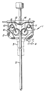
In Fig. 1 there is shown at 1 a cannula for use in
laparoscopic surgery. The cannula comprises a housing 2
and an elongated hollow tube 3 fixed to the bottom wall
of the housing. Only the upper end
5a
208882'
portion of the hollow tube 3 is shown and a valve 4 is
attached to the tube to admit gas through the tube
into the abdominal cavity.
In use, a trocar 5 is passed through the housing
1 and through the hollow tube 3 to cut an incision in
the abdominal wall. The trocar is then removed and
the valve 4 is opened for insufflation of the abdomen.
The cannula remains in place and serves to admit
laparoscopic surgical instruments to enter the abdomen
while maintaining a seal to prevent the escape of the
pressurized gas within the abdomen.
As shown in Fig. 1 there are provided a pair of
rollers 6 and 7 mounted on spring members 8 and 9
respectively which urge the rollers 6 and' 7 towards
the center of the housing. The spring members 8 and
9 are mounted on fixed pins 10 and 11 respectively
and, as shown, one arm of each spring engages a side
wall of the housing and the other arm of the spring
engages a roller to urge the rollers into contact with
20' each other. Referring to Fig. 2 it can be seen that
the end portion of an arm of spring 8 is bent to form ' .
a shaft 12 which extends through roller 6 to provide
an axis for rotation of the roller. Roller 7 is
similarly mounted on an arm of spring 9.
~5 The housing 1 has a centrally disposed downwardly
extending block 13 having a central passageway 14
208882'
extending therethrough as shown in Fig. 4. The lower
faces of the block 13 are curved to receive the
rollers 6 and 7 as shown in Fig. 4. When a trocar or
other surgical instrument is not disposed within the
cannula, the rollers 6 arid 7 are spring-pressed into
contact with each other to close off the passageway 14
and thus prevent escape of pressurized gas from the
abdominal cavity. In Fig. 5 there is shown a bottom
plan view of the housing 2 and showing in dotted lines
the rollers 6 and 7 in face to face engagement to
prevent pressurized air which passes into the housing
2 through opening l5 in the bottom wall of the housing
from escaping to atmosphere.
There is provided in the top wall of the housing
2 a . slidable plate as shown at 16 in Fig. 3. This
slidable plate fits within a slot formed in the top of
the housing member as shown in Fig. 2. The plate has
apertures therein of two different sizes and the plate
can be positioned so that either the large or small
20' opening in the plate is disposed between the opening
17 in the top of the housing member 1. As shown in
Fig: 3, the smaller opening 18 . is disposed directly
beneath aperture 17 which is, of course, aligned with
passageway 14 within the housing Z. The opening 18 is
provided with an elastid diaphragm completely covering
the opening and having a slit therein as shown at 19
7
2osgsz~
in Fig. 3. When a trocar or surgical instrument
having a small diameter is passed through the opening
18, the elastic diaphragm opens along slit 19 to
permit the passage therethxough of the trocar or
surgical instrument. The elastic diaphragm forms a
tight seal surrounding the instrument to prevent
outflow of the pressurized gas within the abdomen.
When larger sized trocars or surgical instruments
are required, the plate 16 is slid to a position where
the larger aperture 20 is in alignment with the
aperture 17. Aperture 20 is also provided with an
elastic diaphragm which is slitted so as to permit the
larger diameter trocar surgical instrument to pass
through the passageway i:n the cannula without loss of
pressurized gas.
In Figs: 6 and 7, there is a disclosed a further
embodiment of the present invention. In this
embodiment, a housing 21 is provided with aligned
openings 24 and 25 in the bottom and top walls
respectively. There is further provided a slidable
plate 26 having a large aperture 27 and a small
aperture 28 having sLitted flexible diaphragms similar
to those described in the Fig. 1 to 5 embodiment. As
shown in Figs. 6 and 7, the plate 26 is slidable
within a slot formed between members 29 and 30.
8
_ 208882 r
Within the housing there are disposed a pair of
rollers 31 and 32 which rollers are rotatably mounted
on pivot arms 33 and 34 respectively and springs 35
and 36 respectively urge the rollers to an abutting
position as shown in Fig. 6.
Disposed beneath the rollers 31 and 32 is an
elastic valve member comprising an elastic sleeve 37
which is retained in position above the aperture 24 on
the bottom wall of housing 21. The elastic sleeve 37
is supported at the upper end by a fixed frame 38
which has a central aperture therein in alignment with
the aperture.
The pivotal arms 35 and 36 have extensions
thereon as shown at 39 and 40 respectively and it can
be seen that when the rollers 31 and 32 are in
abutting relationship, the arms 39 and 40 are forced
into the flexible sleeve 37 so as to close off the
passageway between openings 24 and 25 in the bottom
wall and top wall respectively of the housing 21.
Referring to Fig. 7 it can be seen that a trocar for
surgical instrument 40 has been passed through the
passageway 25 between the rollers 31 and 32 which
forces the arms 39 and 40 outwardly so as to permit
the trocar to pass through the flexible sleeve valve
37 and through the passageway 24. The rollers 31 and
32 in this embodiment of the invention do not perform
9
~08882'~
the function of providing a seal as in the embodiment
of Figs. 1 to 5, the rollers 31 and 32 perform the
function of opening and closing the flexible sleeve
valve 37.
Obviously many modifications and variations of
the present invention are possible in light of the
foregoing teachings. What is claimed as new and is
desired to be secured by Letters Patents is: