Language selection

Search

Patent 2088850 Summary

Third-party information liability

Some of the information on this Web page has been provided by external sources. The Government of Canada is not responsible for the accuracy, reliability or currency of the information supplied by external sources. Users wishing to rely upon this information should consult directly with the source of the information. Content provided by external sources is not subject to official languages, privacy and accessibility requirements.

Claims and Abstract availability

Any discrepancies in the text and image of the Claims and Abstract are due to differing posting times. Text of the Claims and Abstract are posted:

  • At the time the application is open to public inspection;
  • At the time of issue of the patent (grant).
(12) Patent Application: (11) CA 2088850
(54) English Title: DEVICE FOR CARRYING A CHARGE IN A FURNACE
(54) French Title: DISPOSITIF SERVANT A TRANSPORTER UNE CHARGE DANS UN FOUR
Status: Deemed Abandoned and Beyond the Period of Reinstatement - Pending Response to Notice of Disregarded Communication
Bibliographic Data
(51) International Patent Classification (IPC):
  • F27D 3/02 (2006.01)
  • F27D 5/00 (2006.01)
(72) Inventors :
  • HEUSS, HELMUT (Germany)
(73) Owners :
  • LOI ESSEN INDUSTRIEOFENANLAGEN GMBH
(71) Applicants :
  • LOI ESSEN INDUSTRIEOFENANLAGEN GMBH (Germany)
(74) Agent: NORTON ROSE FULBRIGHT CANADA LLP/S.E.N.C.R.L., S.R.L.
(74) Associate agent:
(45) Issued:
(22) Filed Date: 1993-02-05
(41) Open to Public Inspection: 1993-08-11
Examination requested: 2000-02-04
Availability of licence: N/A
Dedicated to the Public: N/A
(25) Language of filing: English

Patent Cooperation Treaty (PCT): No

(30) Application Priority Data:
Application No. Country/Territory Date
P 42 03 595.3 (Germany) 1992-02-10

Abstracts

English Abstract


ABSTRACT OF THE DISCLOSURE
A device for carrying a charge in a reheating furnaces comprising at
least one skid pipe through which a cooling fluid flows, the skid
pipe having at least one rider provided with at least one surface to
support said charge running off center in the longitudinal direction
of the skid pipe. According to the invention neighboring surfaces
are laterally spaced relative to each other and run at least
partially to the side of the skid pipe. Charge exposure to the
relatively low temperature around the skid pipe is kept at a very
low level and charge temperature is therefore very uniform.


Claims

Note: Claims are shown in the official language in which they were submitted.

The embodiments of the invention in which an exclusive
property or privilege is claimed are defined as follows:-
1. A device for carrying a charge and more particularly slabs,
billets, ingots and the like in a furnace, said device com-
prising
- at least one skid pipe defining a longitudinal direction and
a centerline running in said direction, said skid pipe being
capable of carrying a cooling fluid flowing through said
skid pipe; and
- at least two riders capable of withstanding an elevated
temperature arranged on said skid pipe, each such rider
having at least one carrying surface capable of supporting
said charge and running off-center substantially parallel to
said centerline in said longitudinal direction, neighboring
carrying surfaces being laterally spaced relative to each
other and running at least partially to the side of said
skid pipe.
2. The device according to claim 1 wherein each rider has two face
ends, each face end consisting of a first part on the side of
said carrying surface and a second part, said second part pro-
truding in said longitudinal direction from said first part,
said protruding second part of the face end of one of a series
of riders being opposite to the first part of the face end of
the neighboring rider.
3. The device according to claim 1 wherein at least one tilt
stopping means connected with said skid pipe is provided and
wherein at least one of said riders extends below the top
surface of said skid pipe to rest on said tilt stopping means
with its carrying surface above said tilt stopping means.
4. The device according to claim 1 wherein at least one of said
riders is provided with a surface inclined in a direction
transverse to said longitudinal direction to one side of said
carrying surface.

5. The device according to claim 4 wherein said inclined surface is
provided with a cut-out in which a ceramic component is arranged.
6. The device according to claim 1 wherein at least one of said
riders is provided with a surface inclined in said longitudinal
direction to one side of said carrying surface.
7. The device according to claim 6 wherein said inclined surface is
provided with a cut-out in which a ceramic component is arranged.
8. The device according to claim 1 wherein at least one of said
riders is provided with a surface inclined in said longitudinal
direction and in a direction transverse to said longitudinal
direction to one side of said carrying surface.
9. The device according to claim 8 wherein said inclined surface is
provided with a cutout in which a ceramic component is arranged.
10. The device according to claim 1 wherein said skid pipe is provided
with a fitting protruding upwardly into a recess in one of said
riders, a bolt transverse to said longitudinal direction passing
through said rider and said fitting.
11. The device according to claim 1 wherein said riders are steel
castings capable of withstanding an elevated temperature.
12. A device for carrying a charge and more particularly slabs,
billets, ingots and the like in a furnace, said device com-
prising:
- at least one skid pipe defining a longitudinal direction and
a centerline running in said direction, said skid pipe being
capable of carrying a cooling fluid flowing through said
skid pipe;
- at least two riders capable of withstanding an elevated
temperature arranged on said skid pipe, each such rider
having two carrying surfaces capable of supporting said
charge and running off-center substantially parallel to

said centerline in the longitudinal direction thereof, neigh-
boring carrying surfaces being laterally spaced relative to
each other and running at least partially to the side of
said skid pipe and each such rider also having two face
ends, each such face end having a first part on the side of
said carrying surface and a second part, each such second
part protruding relative to the neighboring first part in
said longitudinal direction, the protruding second part of
one in a series of riders being opposite to the first part
of the neighboring rider; and
- at least two tilt stopping means connected with said skid
pipe at least one of said riders extending below the top
surface of said skid pipe and resting on said tilt stopping
means so that at least one of said tilt stopping means is
underneath each carrying surface.
13. The device according to claim 12 wherein at least one of said
riders is provided with a surface inclined in a direction trans-
verse to said longitudinal direction to one side of each carry-
ing surface and each such inclined surface is provided with a
cut-out in which a ceramic component is arranged,
14. The device according to claim 12 wherein said riders axe steel
castings fit for elevated temperature service.

Description

Note: Descriptions are shown in the official language in which they were submitted.


~ ~ ~ $ ~i h ~
Device for Carrying a Charge in a Furnace
B~CKGROVND OF THE INVENTION
The present invention relates to a device for carrying a charge and
more particularly slabs, billets, ingots and the llke in a furnace,
said device comprising at least one skid pipe through which a
cooling fluid flows and at least two riders fit fox service at
elevated temperature arranged on said skid pipe and having at least
one surface to support said charge running off-center substantially
parallel to said skid pipe.
A device of the kind hereinbefore described ls known from German
Patent No. 34 34 356. Said patent divulges a skid system comprising
riders with carrying surfaces located alternately to the left and to
the right of the center plane of the skid system to reduce charge
skid marks attributable to the charge resting on its support. Such
skid marks representing charge areas of relatively low temperature
are a distinct disadvantage because they are the cause of quality
difficiencies such as differences in thickness and width and texture
variations in the rolled product unless said skid marks are removed
prior to rolling by relatively complex and costly operations.
Experience has taught that skid marks may be produced not only by
the surfaces of ridexs carrying the charge in a walking beam furnace
or the like but also by the skid pipes through which cooling fluid
passes thereby creating areas of relatively low temperatureO The
quality deficiencies associated with said relatively cool areas are
becoming increasingly important as specifications of final products
become more and more stringent.
T~E INVENTION
It is an object of the present invention to improve skid systems of
the kind described hereinbefore and to make -provision for a very
even and uniform temperature distribution in the charge by
reasonably simple means which do not have a major impact on
production operations.

- 2 - 2~8 ~s~ ~
To provide such msans the present invention teaches that neighbouring
charge carrying surEaces should be laterally spaced relativ to each
other and run at least partially to the slde of the skid pipe.
The riders of which said surfaces form parts are sequentially
arranged along the skid pipe, the positions of their carrying sur-
faces relative to said skid pipe alternatiny.
The surface areas of said carrying surfaces are minimized for the
mass of the charge they are designed to support. As in accordance
with the present invention said carxying surfaces are at least
partially located to the two sides of said skid pipe off the skid
pipe center, skid marks attributable to the relatively cool area
around the skid pipe are kept at a relatively low level because the
bottom of the charge and above all the part of the charge underside
above the center of the skid pipes may be heated directly beyond the
centerline represented by the skid pipe from alternating sides as it
is exposed for more than half of the charge furnace time.
With respect to such skid marks it is well known that uniform tem-
perature distribution in the charge with substantially no skid marks
is important to maintain specified dimensions more accurately in the
rolling operation following reheating and to obtain a better quality
rolled product.
In a preferred embodiment of the present invention, each face end of
each rider is at the side opposite the charge carrying surface pro-
vided with a protrusion substantially across half of the width of
said face end, the side with said carrying surface thereby being
recessed. The rider protrusion hereinbefore described penetrates
into the recessed part of the next following rider. The inter-
penetration of riders alternately exposed to a force rotating to the
left and to the right respectively interlocks said riders thereby
preventing said riders from being rotated off the skid pipe.
As an alternative in another preferred embodiment of the present
invention each rider extends below the top surface of said skid pipe
and rests on tilt stopping means firmly connected with said skid
pipe underneath its charge carrying surface.

2 ~ 8 ~ ~
Further in another preferred embodiment of the device proposed by
the present invention the rider surface to the side of its charge
carrying surface is roof-shaped and said roof-shaped surface is pro-
vided with a cutout for the insertion of a ceramic component.
Said component may be made from any ceramic material which enhances
the reflection of thermal radiation to increase heat transfer to the
bottom surface of the charge.
The roof-shaped configuration of the rider surface of the area ad-
jacent to the rider's charge carrying surface offers the additional
advantage of preventing scale build-up.
Said surface may be inclined in the direction of charge travel but
is perfectly sloped in the transverse direction because the slope in
the transverse direction may be steeper than the slope in the
longitudinal direction.
Further, in yet another embodiment of the present invention the rider
may be fitted around a fitting on said rider and a bolt is passed
through said fitting and through said rider in a direction trans-
verse to the longitudinal e~tension of the skid pipe. Such a bolted
joint is simple and allows easy rider replacement after removal of
said bolt by a hammer blow or the like without any cutting or
welding operation being necessary.
It is apparent to any skilled person versed in the art that the em-
bodiments of the present invention described hereinbefore may be
combined in various ways without altering the substance of the
present invention.
BRIEF DESCRIPTION OF THE DRAWINGS
The present invention will now be described with the help of pre-
ferred embodiments illustrated in the acompanying drawings.
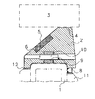
Fig. 1 shows a cross section of an embodiment of the present
invention

~ ~ 2 ~
Fig. 2 shows another embodiment of -the present invention along line
I - I in Fig. 3
Fig. 3 is a partial top view of the embodiment of the present
invention shown in Fig. 2
DETAI~ED DESCRIPTION OF THE PRESENT INVENTION
Referring first to Fig. 1 and Fig. 2, the embodiment of the present
invention shown therein comprises a skid pipe (1) running in the
longitudinal direction of a furnace,. A coollng fluid which may be
water or steam flows through said s}cid pipe for skid pipe cooling.
Said skid pipe (1) is provided with a multiplicity of riders (2) to
carry the charge (3), each such rider (2) has a charge carrying sur-
face (4) on which said charge (3) rests. Said charge carrying surface
(4) runs partially to one side of said skid pipe. Riders (2) are
arranged on said skid pipe in alternating sequence to displace the
charge carrying surfaces (4) of two neighbouring riders relative to
each other thereby allowing the charge bottom and more particularly
the charge bottom area over the center of said skid pipe to be
heated directly beyond the charge centerline from alternating sides
for more than half of the charge furnace time.
To the side of said charge carrying surface (4), a surface (5~ of
the rider (2) is roof-shaped with a lateral slope to allow any scale
to fall down said slope. Said surface (5) is provided with a cut-out
(6) filled by ceramic material which protects the rider made from
cast material for elevated temperature surface against overheating
and enhances heat transfer to the charge bottom by reflecting thermal
radiation.
In the embodimen-t of the present invention depicted in Fig. 1,
strip-type built stopper means (8) welded to skid pipe (1) are pro-
vided below the charge carrying surface (4) of the rider (2).
Said rider (2) fits around a fitting (9) on said skid pipe (1). A
bolt (10) passes through said fitting (9) and said rider (2) in a
direction transverse to the longitudinal direction of said skid pipe

- 5
(l) and is fastened by tack-welding. If necesseary, said bolt (10)
may be removed e~sily by a blow allowing the easy removal of riser
(2).
Said riser (2) extends around the upper part of the cooled skid pipe
(1) approaching the skid pipe insulation system (11), the gap (12)
between said skid pipe insulation system (11) and the rider (2) being
filled with ceramic fiber material.
In the embodiments of the present invention depicted in E'igs. 2 and
3, the sides of the rider faces opposite the charge carrying surface
(4) are provided with protrusions (13) substantially over half the
face width, recesses (1~) recognisable in Fig. 3 thereby being formed
on the riser face sides underneath the charge carrying surface (4).
Each protrusion (14) penetrates into recess (13a) of the neigh-
bouring rider (2a).
Said interpenetration of the riders (2 and 2a) being exposed to
forces acting in the counterclockwise and in the clockwise senses
respectively interlock said riders and thereby prevents said riders
from being turned off said skid pipe.
Fig. 3 is a partial top view of two complete riders (2 and 2a). Gaps
(15) filled with ceramic fiber material or the like are provided
between said two riders to accommodate thermal expansion.
It is apparent to any person versed in the art that further embodi-
ments of the present invention may be devised. A rider may be pro-
vided with more than one (for example two) charge carrying surfaces
arranged in a stagge!red row behind each other. Further, the skid
pipe cross-section may be round or rectangular.

Representative Drawing
A single figure which represents the drawing illustrating the invention.
Administrative Status

2024-08-01:As part of the Next Generation Patents (NGP) transition, the Canadian Patents Database (CPD) now contains a more detailed Event History, which replicates the Event Log of our new back-office solution.

Please note that "Inactive:" events refers to events no longer in use in our new back-office solution.

For a clearer understanding of the status of the application/patent presented on this page, the site Disclaimer , as well as the definitions for Patent , Event History , Maintenance Fee  and Payment History  should be consulted.

Event History

Description Date
Inactive: IPC from MCD 2006-03-11
Application Not Reinstated by Deadline 2004-10-01
Inactive: Dead - No reply to s.30(2) Rules requisition 2004-10-01
Deemed Abandoned - Failure to Respond to Maintenance Fee Notice 2004-02-05
Inactive: Abandoned - No reply to s.30(2) Rules requisition 2003-10-01
Inactive: S.30(2) Rules - Examiner requisition 2003-04-01
Letter Sent 2000-02-18
Inactive: Status info is complete as of Log entry date 2000-02-18
Inactive: Application prosecuted on TS as of Log entry date 2000-02-18
Request for Examination Requirements Determined Compliant 2000-02-04
All Requirements for Examination Determined Compliant 2000-02-04
Application Published (Open to Public Inspection) 1993-08-11

Abandonment History

Abandonment Date Reason Reinstatement Date
2004-02-05

Maintenance Fee

The last payment was received on 2003-01-23

Note : If the full payment has not been received on or before the date indicated, a further fee may be required which may be one of the following

  • the reinstatement fee;
  • the late payment fee; or
  • additional fee to reverse deemed expiry.

Please refer to the CIPO Patent Fees web page to see all current fee amounts.

Fee History

Fee Type Anniversary Year Due Date Paid Date
MF (application, 5th anniv.) - standard 05 1998-02-05 1998-01-28
MF (application, 6th anniv.) - standard 06 1999-02-05 1999-01-20
MF (application, 7th anniv.) - standard 07 2000-02-07 2000-01-14
Request for examination - standard 2000-02-04
MF (application, 8th anniv.) - standard 08 2001-02-05 2001-01-25
MF (application, 9th anniv.) - standard 09 2002-02-05 2002-01-29
MF (application, 10th anniv.) - standard 10 2003-02-05 2003-01-23
Owners on Record

Note: Records showing the ownership history in alphabetical order.

Current Owners on Record
LOI ESSEN INDUSTRIEOFENANLAGEN GMBH
Past Owners on Record
HELMUT HEUSS
Past Owners that do not appear in the "Owners on Record" listing will appear in other documentation within the application.
Documents

To view selected files, please enter reCAPTCHA code :


To view images, click a link in the Document Description column. To download the documents, select one or more checkboxes in the first column and then click the "Download Selected in PDF format (Zip Archive)" or the "Download Selected as Single PDF" button.

List of published and non-published patent-specific documents on the CPD .

If you have any difficulty accessing content, you can call the Client Service Centre at 1-866-997-1936 or send them an e-mail at CIPO Client Service Centre.


Document
Description 
Date
(yyyy-mm-dd) 
Number of pages   Size of Image (KB) 
Representative drawing 1999-08-27 1 12
Cover Page 1993-11-20 1 15
Abstract 1993-11-20 1 16
Claims 1993-11-20 3 108
Drawings 1993-11-20 2 42
Description 1993-11-20 5 210
Reminder - Request for Examination 1999-10-06 1 117
Acknowledgement of Request for Examination 2000-02-18 1 180
Courtesy - Abandonment Letter (R30(2)) 2003-12-10 1 167
Courtesy - Abandonment Letter (Maintenance Fee) 2004-04-01 1 175
Fees 1997-01-22 1 65
Fees 1996-01-31 1 66
Fees 1995-02-01 1 72