Sélection de la langue

Search

Sommaire du brevet 2088850 

Énoncé de désistement de responsabilité concernant l'information provenant de tiers

Une partie des informations de ce site Web a été fournie par des sources externes. Le gouvernement du Canada n'assume aucune responsabilité concernant la précision, l'actualité ou la fiabilité des informations fournies par les sources externes. Les utilisateurs qui désirent employer cette information devraient consulter directement la source des informations. Le contenu fourni par les sources externes n'est pas assujetti aux exigences sur les langues officielles, la protection des renseignements personnels et l'accessibilité.

Disponibilité de l'Abrégé et des Revendications

L'apparition de différences dans le texte et l'image des Revendications et de l'Abrégé dépend du moment auquel le document est publié. Les textes des Revendications et de l'Abrégé sont affichés :

  • lorsque la demande peut être examinée par le public;
  • lorsque le brevet est émis (délivrance).
(12) Demande de brevet: (11) CA 2088850
(54) Titre français: DISPOSITIF SERVANT A TRANSPORTER UNE CHARGE DANS UN FOUR
(54) Titre anglais: DEVICE FOR CARRYING A CHARGE IN A FURNACE
Statut: Réputée abandonnée et au-delà du délai pour le rétablissement - en attente de la réponse à l’avis de communication rejetée
Données bibliographiques
(51) Classification internationale des brevets (CIB):
  • F27D 3/02 (2006.01)
  • F27D 5/00 (2006.01)
(72) Inventeurs :
  • HEUSS, HELMUT (Allemagne)
(73) Titulaires :
  • LOI ESSEN INDUSTRIEOFENANLAGEN GMBH
(71) Demandeurs :
  • LOI ESSEN INDUSTRIEOFENANLAGEN GMBH (Allemagne)
(74) Agent: NORTON ROSE FULBRIGHT CANADA LLP/S.E.N.C.R.L., S.R.L.
(74) Co-agent:
(45) Délivré:
(22) Date de dépôt: 1993-02-05
(41) Mise à la disponibilité du public: 1993-08-11
Requête d'examen: 2000-02-04
Licence disponible: S.O.
Cédé au domaine public: S.O.
(25) Langue des documents déposés: Anglais

Traité de coopération en matière de brevets (PCT): Non

(30) Données de priorité de la demande:
Numéro de la demande Pays / territoire Date
P 42 03 595.3 (Allemagne) 1992-02-10

Abrégés

Abrégé anglais


ABSTRACT OF THE DISCLOSURE
A device for carrying a charge in a reheating furnaces comprising at
least one skid pipe through which a cooling fluid flows, the skid
pipe having at least one rider provided with at least one surface to
support said charge running off center in the longitudinal direction
of the skid pipe. According to the invention neighboring surfaces
are laterally spaced relative to each other and run at least
partially to the side of the skid pipe. Charge exposure to the
relatively low temperature around the skid pipe is kept at a very
low level and charge temperature is therefore very uniform.

Revendications

Note : Les revendications sont présentées dans la langue officielle dans laquelle elles ont été soumises.


The embodiments of the invention in which an exclusive
property or privilege is claimed are defined as follows:-
1. A device for carrying a charge and more particularly slabs,
billets, ingots and the like in a furnace, said device com-
prising
- at least one skid pipe defining a longitudinal direction and
a centerline running in said direction, said skid pipe being
capable of carrying a cooling fluid flowing through said
skid pipe; and
- at least two riders capable of withstanding an elevated
temperature arranged on said skid pipe, each such rider
having at least one carrying surface capable of supporting
said charge and running off-center substantially parallel to
said centerline in said longitudinal direction, neighboring
carrying surfaces being laterally spaced relative to each
other and running at least partially to the side of said
skid pipe.
2. The device according to claim 1 wherein each rider has two face
ends, each face end consisting of a first part on the side of
said carrying surface and a second part, said second part pro-
truding in said longitudinal direction from said first part,
said protruding second part of the face end of one of a series
of riders being opposite to the first part of the face end of
the neighboring rider.
3. The device according to claim 1 wherein at least one tilt
stopping means connected with said skid pipe is provided and
wherein at least one of said riders extends below the top
surface of said skid pipe to rest on said tilt stopping means
with its carrying surface above said tilt stopping means.
4. The device according to claim 1 wherein at least one of said
riders is provided with a surface inclined in a direction
transverse to said longitudinal direction to one side of said
carrying surface.

5. The device according to claim 4 wherein said inclined surface is
provided with a cut-out in which a ceramic component is arranged.
6. The device according to claim 1 wherein at least one of said
riders is provided with a surface inclined in said longitudinal
direction to one side of said carrying surface.
7. The device according to claim 6 wherein said inclined surface is
provided with a cut-out in which a ceramic component is arranged.
8. The device according to claim 1 wherein at least one of said
riders is provided with a surface inclined in said longitudinal
direction and in a direction transverse to said longitudinal
direction to one side of said carrying surface.
9. The device according to claim 8 wherein said inclined surface is
provided with a cutout in which a ceramic component is arranged.
10. The device according to claim 1 wherein said skid pipe is provided
with a fitting protruding upwardly into a recess in one of said
riders, a bolt transverse to said longitudinal direction passing
through said rider and said fitting.
11. The device according to claim 1 wherein said riders are steel
castings capable of withstanding an elevated temperature.
12. A device for carrying a charge and more particularly slabs,
billets, ingots and the like in a furnace, said device com-
prising:
- at least one skid pipe defining a longitudinal direction and
a centerline running in said direction, said skid pipe being
capable of carrying a cooling fluid flowing through said
skid pipe;
- at least two riders capable of withstanding an elevated
temperature arranged on said skid pipe, each such rider
having two carrying surfaces capable of supporting said
charge and running off-center substantially parallel to

said centerline in the longitudinal direction thereof, neigh-
boring carrying surfaces being laterally spaced relative to
each other and running at least partially to the side of
said skid pipe and each such rider also having two face
ends, each such face end having a first part on the side of
said carrying surface and a second part, each such second
part protruding relative to the neighboring first part in
said longitudinal direction, the protruding second part of
one in a series of riders being opposite to the first part
of the neighboring rider; and
- at least two tilt stopping means connected with said skid
pipe at least one of said riders extending below the top
surface of said skid pipe and resting on said tilt stopping
means so that at least one of said tilt stopping means is
underneath each carrying surface.
13. The device according to claim 12 wherein at least one of said
riders is provided with a surface inclined in a direction trans-
verse to said longitudinal direction to one side of each carry-
ing surface and each such inclined surface is provided with a
cut-out in which a ceramic component is arranged,
14. The device according to claim 12 wherein said riders axe steel
castings fit for elevated temperature service.

Description

Note : Les descriptions sont présentées dans la langue officielle dans laquelle elles ont été soumises.

~ ~ ~ $ ~i h ~
Device for Carrying a Charge in a Furnace
B~CKGROVND OF THE INVENTION
The present invention relates to a device for carrying a charge and
more particularly slabs, billets, ingots and the llke in a furnace,
said device comprising at least one skid pipe through which a
cooling fluid flows and at least two riders fit fox service at
elevated temperature arranged on said skid pipe and having at least
one surface to support said charge running off-center substantially
parallel to said skid pipe.
A device of the kind hereinbefore described ls known from German
Patent No. 34 34 356. Said patent divulges a skid system comprising
riders with carrying surfaces located alternately to the left and to
the right of the center plane of the skid system to reduce charge
skid marks attributable to the charge resting on its support. Such
skid marks representing charge areas of relatively low temperature
are a distinct disadvantage because they are the cause of quality
difficiencies such as differences in thickness and width and texture
variations in the rolled product unless said skid marks are removed
prior to rolling by relatively complex and costly operations.
Experience has taught that skid marks may be produced not only by
the surfaces of ridexs carrying the charge in a walking beam furnace
or the like but also by the skid pipes through which cooling fluid
passes thereby creating areas of relatively low temperatureO The
quality deficiencies associated with said relatively cool areas are
becoming increasingly important as specifications of final products
become more and more stringent.
T~E INVENTION
It is an object of the present invention to improve skid systems of
the kind described hereinbefore and to make -provision for a very
even and uniform temperature distribution in the charge by
reasonably simple means which do not have a major impact on
production operations.

- 2 - 2~8 ~s~ ~
To provide such msans the present invention teaches that neighbouring
charge carrying surEaces should be laterally spaced relativ to each
other and run at least partially to the slde of the skid pipe.
The riders of which said surfaces form parts are sequentially
arranged along the skid pipe, the positions of their carrying sur-
faces relative to said skid pipe alternatiny.
The surface areas of said carrying surfaces are minimized for the
mass of the charge they are designed to support. As in accordance
with the present invention said carxying surfaces are at least
partially located to the two sides of said skid pipe off the skid
pipe center, skid marks attributable to the relatively cool area
around the skid pipe are kept at a relatively low level because the
bottom of the charge and above all the part of the charge underside
above the center of the skid pipes may be heated directly beyond the
centerline represented by the skid pipe from alternating sides as it
is exposed for more than half of the charge furnace time.
With respect to such skid marks it is well known that uniform tem-
perature distribution in the charge with substantially no skid marks
is important to maintain specified dimensions more accurately in the
rolling operation following reheating and to obtain a better quality
rolled product.
In a preferred embodiment of the present invention, each face end of
each rider is at the side opposite the charge carrying surface pro-
vided with a protrusion substantially across half of the width of
said face end, the side with said carrying surface thereby being
recessed. The rider protrusion hereinbefore described penetrates
into the recessed part of the next following rider. The inter-
penetration of riders alternately exposed to a force rotating to the
left and to the right respectively interlocks said riders thereby
preventing said riders from being rotated off the skid pipe.
As an alternative in another preferred embodiment of the present
invention each rider extends below the top surface of said skid pipe
and rests on tilt stopping means firmly connected with said skid
pipe underneath its charge carrying surface.

2 ~ 8 ~ ~
Further in another preferred embodiment of the device proposed by
the present invention the rider surface to the side of its charge
carrying surface is roof-shaped and said roof-shaped surface is pro-
vided with a cutout for the insertion of a ceramic component.
Said component may be made from any ceramic material which enhances
the reflection of thermal radiation to increase heat transfer to the
bottom surface of the charge.
The roof-shaped configuration of the rider surface of the area ad-
jacent to the rider's charge carrying surface offers the additional
advantage of preventing scale build-up.
Said surface may be inclined in the direction of charge travel but
is perfectly sloped in the transverse direction because the slope in
the transverse direction may be steeper than the slope in the
longitudinal direction.
Further, in yet another embodiment of the present invention the rider
may be fitted around a fitting on said rider and a bolt is passed
through said fitting and through said rider in a direction trans-
verse to the longitudinal e~tension of the skid pipe. Such a bolted
joint is simple and allows easy rider replacement after removal of
said bolt by a hammer blow or the like without any cutting or
welding operation being necessary.
It is apparent to any skilled person versed in the art that the em-
bodiments of the present invention described hereinbefore may be
combined in various ways without altering the substance of the
present invention.
BRIEF DESCRIPTION OF THE DRAWINGS
The present invention will now be described with the help of pre-
ferred embodiments illustrated in the acompanying drawings.
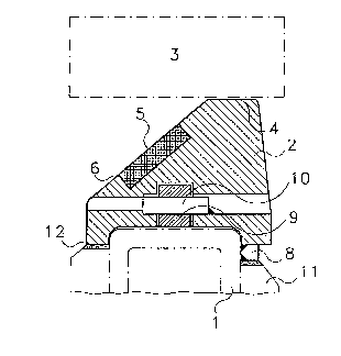
Fig. 1 shows a cross section of an embodiment of the present
invention

~ ~ 2 ~
Fig. 2 shows another embodiment of -the present invention along line
I - I in Fig. 3
Fig. 3 is a partial top view of the embodiment of the present
invention shown in Fig. 2
DETAI~ED DESCRIPTION OF THE PRESENT INVENTION
Referring first to Fig. 1 and Fig. 2, the embodiment of the present
invention shown therein comprises a skid pipe (1) running in the
longitudinal direction of a furnace,. A coollng fluid which may be
water or steam flows through said s}cid pipe for skid pipe cooling.
Said skid pipe (1) is provided with a multiplicity of riders (2) to
carry the charge (3), each such rider (2) has a charge carrying sur-
face (4) on which said charge (3) rests. Said charge carrying surface
(4) runs partially to one side of said skid pipe. Riders (2) are
arranged on said skid pipe in alternating sequence to displace the
charge carrying surfaces (4) of two neighbouring riders relative to
each other thereby allowing the charge bottom and more particularly
the charge bottom area over the center of said skid pipe to be
heated directly beyond the charge centerline from alternating sides
for more than half of the charge furnace time.
To the side of said charge carrying surface (4), a surface (5~ of
the rider (2) is roof-shaped with a lateral slope to allow any scale
to fall down said slope. Said surface (5) is provided with a cut-out
(6) filled by ceramic material which protects the rider made from
cast material for elevated temperature surface against overheating
and enhances heat transfer to the charge bottom by reflecting thermal
radiation.
In the embodimen-t of the present invention depicted in Fig. 1,
strip-type built stopper means (8) welded to skid pipe (1) are pro-
vided below the charge carrying surface (4) of the rider (2).
Said rider (2) fits around a fitting (9) on said skid pipe (1). A
bolt (10) passes through said fitting (9) and said rider (2) in a
direction transverse to the longitudinal direction of said skid pipe

- 5
(l) and is fastened by tack-welding. If necesseary, said bolt (10)
may be removed e~sily by a blow allowing the easy removal of riser
(2).
Said riser (2) extends around the upper part of the cooled skid pipe
(1) approaching the skid pipe insulation system (11), the gap (12)
between said skid pipe insulation system (11) and the rider (2) being
filled with ceramic fiber material.
In the embodiments of the present invention depicted in E'igs. 2 and
3, the sides of the rider faces opposite the charge carrying surface
(4) are provided with protrusions (13) substantially over half the
face width, recesses (1~) recognisable in Fig. 3 thereby being formed
on the riser face sides underneath the charge carrying surface (4).
Each protrusion (14) penetrates into recess (13a) of the neigh-
bouring rider (2a).
Said interpenetration of the riders (2 and 2a) being exposed to
forces acting in the counterclockwise and in the clockwise senses
respectively interlock said riders and thereby prevents said riders
from being turned off said skid pipe.
Fig. 3 is a partial top view of two complete riders (2 and 2a). Gaps
(15) filled with ceramic fiber material or the like are provided
between said two riders to accommodate thermal expansion.
It is apparent to any person versed in the art that further embodi-
ments of the present invention may be devised. A rider may be pro-
vided with more than one (for example two) charge carrying surfaces
arranged in a stagge!red row behind each other. Further, the skid
pipe cross-section may be round or rectangular.

Dessin représentatif
Une figure unique qui représente un dessin illustrant l'invention.
États administratifs

2024-08-01 : Dans le cadre de la transition vers les Brevets de nouvelle génération (BNG), la base de données sur les brevets canadiens (BDBC) contient désormais un Historique d'événement plus détaillé, qui reproduit le Journal des événements de notre nouvelle solution interne.

Veuillez noter que les événements débutant par « Inactive : » se réfèrent à des événements qui ne sont plus utilisés dans notre nouvelle solution interne.

Pour une meilleure compréhension de l'état de la demande ou brevet qui figure sur cette page, la rubrique Mise en garde , et les descriptions de Brevet , Historique d'événement , Taxes périodiques et Historique des paiements devraient être consultées.

Historique d'événement

Description Date
Inactive : CIB de MCD 2006-03-11
Demande non rétablie avant l'échéance 2004-10-01
Inactive : Morte - Aucune rép. dem. par.30(2) Règles 2004-10-01
Réputée abandonnée - omission de répondre à un avis sur les taxes pour le maintien en état 2004-02-05
Inactive : Abandon. - Aucune rép dem par.30(2) Règles 2003-10-01
Inactive : Dem. de l'examinateur par.30(2) Règles 2003-04-01
Lettre envoyée 2000-02-18
Inactive : Renseign. sur l'état - Complets dès date d'ent. journ. 2000-02-18
Inactive : Dem. traitée sur TS dès date d'ent. journal 2000-02-18
Exigences pour une requête d'examen - jugée conforme 2000-02-04
Toutes les exigences pour l'examen - jugée conforme 2000-02-04
Demande publiée (accessible au public) 1993-08-11

Historique d'abandonnement

Date d'abandonnement Raison Date de rétablissement
2004-02-05

Taxes périodiques

Le dernier paiement a été reçu le 2003-01-23

Avis : Si le paiement en totalité n'a pas été reçu au plus tard à la date indiquée, une taxe supplémentaire peut être imposée, soit une des taxes suivantes :

  • taxe de rétablissement ;
  • taxe pour paiement en souffrance ; ou
  • taxe additionnelle pour le renversement d'une péremption réputée.

Veuillez vous référer à la page web des taxes sur les brevets de l'OPIC pour voir tous les montants actuels des taxes.

Historique des taxes

Type de taxes Anniversaire Échéance Date payée
TM (demande, 5e anniv.) - générale 05 1998-02-05 1998-01-28
TM (demande, 6e anniv.) - générale 06 1999-02-05 1999-01-20
TM (demande, 7e anniv.) - générale 07 2000-02-07 2000-01-14
Requête d'examen - générale 2000-02-04
TM (demande, 8e anniv.) - générale 08 2001-02-05 2001-01-25
TM (demande, 9e anniv.) - générale 09 2002-02-05 2002-01-29
TM (demande, 10e anniv.) - générale 10 2003-02-05 2003-01-23
Titulaires au dossier

Les titulaires actuels et antérieures au dossier sont affichés en ordre alphabétique.

Titulaires actuels au dossier
LOI ESSEN INDUSTRIEOFENANLAGEN GMBH
Titulaires antérieures au dossier
HELMUT HEUSS
Les propriétaires antérieurs qui ne figurent pas dans la liste des « Propriétaires au dossier » apparaîtront dans d'autres documents au dossier.
Documents

Pour visionner les fichiers sélectionnés, entrer le code reCAPTCHA :


Pour visualiser une image, cliquer sur un lien dans la colonne description du document. Pour télécharger l'image (les images), cliquer l'une ou plusieurs cases à cocher dans la première colonne et ensuite cliquer sur le bouton "Télécharger sélection en format PDF (archive Zip)" ou le bouton "Télécharger sélection (en un fichier PDF fusionné)".

Liste des documents de brevet publiés et non publiés sur la BDBC .

Si vous avez des difficultés à accéder au contenu, veuillez communiquer avec le Centre de services à la clientèle au 1-866-997-1936, ou envoyer un courriel au Centre de service à la clientèle de l'OPIC.


Description du
Document 
Date
(aaaa-mm-jj) 
Nombre de pages   Taille de l'image (Ko) 
Dessin représentatif 1999-08-27 1 12
Page couverture 1993-11-20 1 15
Abrégé 1993-11-20 1 16
Revendications 1993-11-20 3 108
Dessins 1993-11-20 2 42
Description 1993-11-20 5 210
Rappel - requête d'examen 1999-10-06 1 117
Accusé de réception de la requête d'examen 2000-02-18 1 180
Courtoisie - Lettre d'abandon (R30(2)) 2003-12-10 1 167
Courtoisie - Lettre d'abandon (taxe de maintien en état) 2004-04-01 1 175
Taxes 1997-01-22 1 65
Taxes 1996-01-31 1 66
Taxes 1995-02-01 1 72