Note: Descriptions are shown in the official language in which they were submitted.
~` 2~88899
FIELD OF T}IE: I~E~ION
The present invention relates to the art of
manufacturing hockey sticks and, more particularly, to a
replacement blade for a hockey stick and to methods for
manufacturing same. The invention also extends to a novel
replacement blade blank permitting to manufacture
simultaneously a pair of individual replacement blades.
BACXGRO~ND OF T~E INVENTION
Traditionally, hockey sticks have been manufactured
entirely from hardwood selected to provide the desired
combination of strength, rigidity and optimal weight. Due
to the increasing rarity of suitable raw material,
manufacturers have turned to modern material science to
seek practical alternatives. In this regard, glass-
fibers/softwood composites have shown good potential,
allowing to manufacture highly performant hockey sticks at
reasonable cost.
Hockey sticks made of composite materials are usually
manufactured as structurally integral units by permanently
affixing the blade to the handle and then wrapping the
assembly with a reinforcing layer of synthetic fibrous
material stabilized in synthetic resin. A disadvantage of
this mode of construction resides in that if one component
2088899
-- 2 --
of the hockey stick fails, the entire unit is rendered
useless and must be discarded. More specifically,
breakage of a hockey stick would typically occur in the
region of the blade which is subjected to high stresses
when the player violently strikes the puck. Accordingly,
if the blade of the hockey stick is damaged beyond repair,
the handle is rendered useless even though it remains a ~ -
functional component.
'
10To alleviate this drawback, some manufacturers have
recently developed modular hockey sticks featuring
replaceable blades. The ultimate user of the product
would typically purchase a high quality, long lasting
handle, made from extruded aluminum for example, to which
is mounted a removable blade. The latter comprises a
blade portion from which projects a relatively short shank
terminating at its upper end by a section having a reduced
thickness which is designed to slidingly engage a socket
on the lower extremity of the handle. A secure joint is
made between the handle and the blade by a suitable
adhesive r
Although modular hockey sticks present significant
advantages, it has been observed that the removable blade
has a tendency to fail prematurely at relatively low
stress levels. A possible explanation of this phenomenon
is the creation of a weakness zone on the replacement
- 2088899
blade at the area of union between the redu ed thickness
zone of the shank and the lower portion of the shank.
Under high stress conditions, cracks may form at this
weakness zone, causing a major delamination which
propagates along the interface of the glass fibers layer
and the wooden layer.
OBJE~:r8 AND 8TATEMENT OF ~Æ INVBNI~ION
An object of the present invention is a novel hockey
stick construction suitable for manufacturing individual
replacement blades or hockey sticks in which the blade is
permanently united to the handle, permitting to achieve a
strong bond between a synthetic fibrous layer and a layer
of wooden material, which is highly resistant to
delamination.
Another object of the invention is a method for
manufacturing the aforementioned hockey stick and
replacement blade.
A further object of the invention is a novel method
for producing simultaneously a pair of replacement blades.
_ 4 2088899
Yet, another object of the invention is a novel
replacement blade blank used for manufacturing
simultaneously a pair of replacement blades.
As embodied and broadly described herein, the
invention provides a replacement blade for a hockey stick,
comprising:
- a puck engaging member:
- a shank projecting from the puck engaging
member for engaging a hockey stick handle, the shank
including:
a) a core having a pair of opposite lateral
surfaces;
b) a laminated reinforcing element mounted
to each lateral ~urface of the core to impart strength and
rigidity to said core, the laminated reinforcing element
including:
i) a layer of synthetic fibers bonded
in a face-to-face relationship to a respective lateral
surface of the core;
ii~ a veneer fully saturated with
bonding medium adhered to the layer of synthetic fibers;
iii) a layer of wooden material
substantially thicker than the veneer and adhered thereto,
said veneer extending at an interface between the layers
and constituting means for increasing bond strength
therebetween.
- 5 - 2088~99 :
By interposing a thin veneer impregnated with bonding
medium, such as a synthetic resin or any other suitable
substance between the synthetic fibers layer and the layer
of wood, a considerably stronger layer-to-lay~r bond is
achieved by comparison to a composite structure in which
the synthetic fibers layer is directly united to the thick
wood layer.
This form of construction is applicable equally well
to hockey sticks in which the blade is permanently affixed
to the handle as well as to the manufacture of replacement
blades. In the latter case, the increased bond strength
between the ~ynthetic fibrous layer and the thick wood
layer significantly reduces the risks of delamination of
the blade when the latter is subjected to intense
mechanical stresses.
In a most preferred embodiment, the shank of the
blade comprises an elongated core of soft wosd material
of rectangular cross-sectional shape having a pair of main
opposite surfaces. Each stratified reinforcing element,
affixed to a respective main surface of the core, includes
a first layer of glass fibers oriented along the
longitudinal axis of the core and which is directly bonded
: : :
thereto. A veneer impregnated with synthetic resin is
mounted to the layer of glass fibers. A pair of
identical, thick, hardwood layers, having individual
- 6 - 2088~99
thicknesses significantly exceeding the thickness of the
veneer are superposed thereto in order to complete the
assembly.
The outer surface of the shank constituted by the
dual layer of hardwood material is machined to form on the
shank an upper region of reduced thickness closely
conforming to the blade receiving socket at the lower end
of the handle. This operation involves the removal of
significant amounts of wood material which leaves a
~houlder forming an area of union between the reduced
thickness zone and the remaining portion of the shank.
As embodied and broadly described herein, the
invention also provides a hockey stick, comprising:
- a puck engaging member;
- a shank projecting from the puck engaging
member, the shank including:
a) a core having a pair of opposite lateral
surfaces;
b) a laminated reinforcing element mounted
.
to each lateral surface of the core to impart strength and
rigidity to the core, said laminated reinforcing element
including:
2088899
i~ a layer of synthetic fibers bonded
in a face-to-face relationship to a respective lateral
surface of the core;
ii) a veneer fully saturated with
bonding medium and adhered to the layer of synthetic
fibers;
iii) a layer of wooden material
substantially thicker than the veneer and adhered thereto,
the veneer extending at an interface between the layers
and constituting means for increasing bond strength
therebetween.
As embodied and broadly described herein the
invention further provides a method for manufacturing a
replacement blade comprising a puck engaging member and a
projecting shank for connecting the puck engaging member
to a handle of a hockey stick, the method comprising the
steps of:
- providing a core of wooden material having a
pair of opposite lateral surfaces;
- depositing against each lateral surface of the
core a layer of synthetic fibers;
- depositing against each layer of synthetic
fibers a veneer;
- depositing against each veneer a layer of
wooden material substantially thicker than the veneer;
- 8 - 20 8 8899
- saturating the veneers with uncured bonding
medium;
- bonding the layers of synthetic fibers to the
core and curing the bonding medium to intimately unite the
layers of wooden material to a respective layer of
synthetic fibers through the intermediary of the veneers,
thereby forming a laminated structurally integral
assembly;
- forming a puck engaging member at an extremity
of the laminated structurally integral assembly.
In a preferred embodiment, the various lay2rs
constituting the shank are deposited in a superposed
relationship in a mould having a suitable shape and
uncured resin is applied between the various layers of the
assembly, particularly to the veneers to fully saturate
the thin wood sheets. The mould is then closed to create
a mechanical pressure on the laminated structure and the
temperature in the mould is elevated to cure th resin.
A puck engaging member, manufactured according to
traditional techniques is then attached to the shank.
Finally, the upper extremity of the shank is machined to
form the section of reduced thickness provided for
engaging the socket at the lower end of the handle of the
hockey stick.
2088899
Most preferably, a wide laminated board, having the
same stratification as the shank is formed in a mould as
described above. The board is cut longitudinally into a
plurality of long shaft-like members. Puck engaging
members are affixed at opposite extremities of each shaft-
like member to form a pair of siamese replacement blades.
Each shaft-like member is then cut transversally and the
resulting individual replacement blades are subjected to
the appropriate finishing operations.
As embodied and broadly described herein, the
invention provides a blank of a replacement blade for a
hockey stick, comprising~
- a pair of puck engaging members in a spaced apart
relationship;
- a shaft-like member interconnecting the puck
engaging memb~r.
BRIEF DE~CRIPTION OF THB DR~WING5
~ :
- Figure 1 is a perspective view of a hockey stick
having a modular construction having a handle to which is
removably mounted a replaceable blade;
-- 10 --
2~88899 ~ ~- Figure 2 is a fragmentary, perspective view of the
joint between the handle and the replaceable blade of the
hockey stick;
- Figure 3 is a cross-sectional view along lines 3-
3 in Figure 1;
- Figure 4 is an exploded view of a laminated board
for manufacturing simultaneously shanks for replacement
blades in acoordance with the invention;
- Figure 5 illustrates the laminated board of Figure :~
4 in a fully assembled condition; and -
- Figure 6 is a perspective view of a blank for
simultaneously manufacturing a pair of replacement blades.
DE~CRIPTION OF A PREF~RRED EMBODIMENT
With reference to the annexed drawings, Figure 1
illustrates a hockey ~tick of modular construction
designated comprehensively by the reference numeral 10,
comprising a handle 12 to which is releasably mounted a
replacement blade 14. The latter can be separated from
the handle 12 permitting to reuse the handle 12 if the
blade 14 is damaged.
2088899
The blade 14 comprises a paddle-shaped puck engaging
member 16 from which projects upwardly a shank 18 having
a generally rectangular cross-section closely conforming
to the outer cross-sectional shape of the handle 12. The
upper end of the shank 18 has a section 20 of reduced
thickness forming a tongue 22 closely conforming to a
socket 24 provided on the lower end of the handle 12.
peripherally extending shoulder 26 having a height
corresponding generally to the wall thickness of the
handle 12 extends at the area of union between the tongue
22 and the lower portion of the shank 18. The shoulder 26
constitutes an abutment which is engaged by the lower
extremity of the handle 12 when the tongue 22 is slidingly
inserted in the socket 24. To prevent undesirable removal
of the blade 14 from the handle 12, the tongue 22 is
coated with a suitable adhesive. Adhesives of the hot-
melt type have been found advantageous allowing to release
the bond by the application of heat when replacement of
the blade 14 is required. ~ i
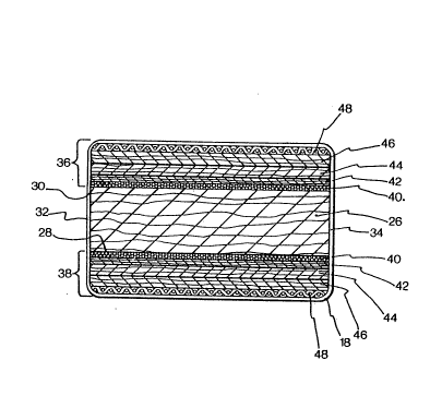
With reference to Figure 3, the shank 18 has a
laminated construction comprising a central core 26 made
of soft wood material of rectangular cross-sectional
shape. As a re~ult of this configuration, the core 26 has
a pair of primary opposite lateral surfaces 28 and 30 and
a pair of opposed smaller surfaces 32 and 34. On the
lateral surfaces 28 and 30 of the core 26 are bonded
- 12 - 2088~99
stratified reinforcing element 36 and 38, respectively.
Each reinforcing element comprises a layer of
unidirectional glass fibers 40, i.e. a layer in which the
glass fibers are parallel to one another and extend along
the longitudinal axis of the shank 18. As it is customary
in the art, the glass fibers of the layer 40 are embedded
in a mass of synthetic resin. On top of the layer 40 is
mounted a veneer 42 constituted by a thin sheet of
hardwood material which typically has a thickness of less
than 1 millimeter.
A critical aspect of the invention resides in that
the veneer forming the layer 42 is fully saturated with
bonding medium capable of strongly adhering to the
synthetic fibrous layer 40. Such bonding medium may be
synthetia resin which, when cured, intimately associates
the layers 40 and 42. Since the layer 42 is very thin,
the impregnation process can be achieved relatively
easily, for example, by soaking the veneer in a bath of
uncured resin or simply by depositing during the assembly
of the shank 18 sufficient quantities of uncured resin on
both sides of the layer 42.
on top of the layer 42 are mounted two identical
layers of hardwood material 44 and 46, respectively. The
bonding of the layers 44 and 46 to one another, as well as
the bonding of layer 44 to the layer 42 is achieved by the
- 13 - 2 0 8 8g9 9
same synthetic resin used for uniting the layers 40 to 42.
Each of the layers 44 and 46 is significantly thicker than
the veneer forming layer 42, typically in the order of two
millimeters. ~ `~
To complete the assembly of the shank 18, a woven
cloth of glass fibers 48 coated with synthetic resin, i-
~laid on the wood layers 46. The resin in the cloth is
then cured according to known technigues. The application
of an outer wrap of woven glass fibers cloth is common in
the art of manufacturing hockey sticks and it is used
primarily to further reinforce the stick by forming on its
outer surface a hard, wear-resistant shell.
The method for manufacturing the replacement blade 14
will now be described in connection with Figures 4, 5 and
6.
Broadly stated, the method consists of manufacturing
first a laminated board which is then cut longitudinally
to form a pair of siamesed shanks. Puck engaging members
are formed on each shank and the resultant assembly is cut
to form a pair of individual replacement blades.
An exploded view of the laminated board, designated
comprehensively by the reference numeral 50 is shown in
Figure 4. It will be apparent that the arrangement of the
5`~
- 14 -
2088899
various layers is identical to the disposition of the
various layers in the shank 18 except that the synthetic
fibers layers 40 are discontinuous and are present only in
the end regions of the laminated board 50.
The width of the various layers forming the laminated
board 50 is several times the transverse dimension of the
shank 18, allowing to manufacture simultaneously a
plurality of shanks from a single board 50.
To manufacture the board 50, the various layers are
deposited in a superposed relationship in the proper order
and coated with the suitable synthetic resin. The
assembly is then laid in a heated shaping mold which
presses the layers together under high temperature
conditions to cure the assembly and form a structurally
integral unit. The resulting board 50 is shown in Figure
5.
The next operation consists of cutting longitudinally
the laminated board 50 to form a plurality of elongated,
shaft-like members 52. Each member 52 is constituted by
a pair of siamesed shanks 18 united to one another by a
central region 54 which is free of the layers 40
constituted by synthetic fibers.
- 15 - 2088899 : ~
Subsequently, the individual shaft-like members 52
are machined to form at their extremities central,
longitudinally extending slits (not shown in the drawings)
in which are inserted boards 54 to form the puck engaging
members 16. Reinforcement blocks 56 are also applied and
the resultant assembly is finished according to known
processes to form a pair of replacement blades united by
their shank portions. The member 52 is then transversely
cut at two lsngitudinally spaced apart locations, each one
corresponding to a juncture between the central region 54
and the end regions containing a reinfsrcing glass fiber
layers. The manufacturing process is completed by
machining the upper extremities of the shanks 18 to form
the tongues 22.
The remaining central segment 54 is then cut in half
and can be used for making the reinforcement blocks 56
when manufacturing another pair of replacement blades.
The method of manufacture of replacement blades in
accordance with the invention has been found particularly
advantageous by allowing to produce two replacement blades
at the same time. Since the blades remain united to one
another in a single assembly during substantially the
entire manufacturing process, the manipulation of the
blades is made much simpler and waste is reduced, thereby
2 o 8 8 8 g 9
- 16 -
rendering the entire process less time consuming and more
cost effective.
The above description of the present invention should
not be interpreted in any limiting manner since
refinements and variations are possible without departing
from the spirit of the invention. The scope of the
invention is defined in the appended claims and their
equivalents.