Language selection

Search

Patent 2088914 Summary

Third-party information liability

Some of the information on this Web page has been provided by external sources. The Government of Canada is not responsible for the accuracy, reliability or currency of the information supplied by external sources. Users wishing to rely upon this information should consult directly with the source of the information. Content provided by external sources is not subject to official languages, privacy and accessibility requirements.

Claims and Abstract availability

Any discrepancies in the text and image of the Claims and Abstract are due to differing posting times. Text of the Claims and Abstract are posted:

  • At the time the application is open to public inspection;
  • At the time of issue of the patent (grant).
(12) Patent: (11) CA 2088914
(54) English Title: SHEET-WOUND COILS
(54) French Title: BOBINES A ENROULEMENT EN BANDE
Status: Expired and beyond the Period of Reversal
Bibliographic Data
(51) International Patent Classification (IPC):
  • H01F 27/28 (2006.01)
  • H01F 41/10 (2006.01)
(72) Inventors :
  • FORSBERG, ERIK (Sweden)
  • LUNDSTROM, LENNART (Sweden)
  • ZETTERLUND, UNO (Sweden)
(73) Owners :
  • ASEA BROWN BOVERI AB
(71) Applicants :
  • ASEA BROWN BOVERI AB (Sweden)
(74) Agent: ROBIC AGENCE PI S.E.C./ROBIC IP AGENCY LP
(74) Associate agent:
(45) Issued: 1996-05-07
(86) PCT Filing Date: 1991-07-01
(87) Open to Public Inspection: 1992-02-08
Examination requested: 1995-01-16
Availability of licence: N/A
Dedicated to the Public: N/A
(25) Language of filing: English

Patent Cooperation Treaty (PCT): Yes
(86) PCT Filing Number: PCT/SE1991/000471
(87) International Publication Number: SE1991000471
(85) National Entry: 1993-02-04

(30) Application Priority Data:
Application No. Country/Territory Date
9002585-9 (Sweden) 1990-08-07

Abstracts

English Abstract


A procedure when joining the tail ends of sheet-wound coils (1, 2)
stacked one on top of the other around an inductive apparatus core with a
certain axial space between them, the joint being effected using a thin
leader strip (3) which is connected to adjacent parts of the coils and joined
to the coils along almost one coil turn.


Claims

Note: Claims are shown in the official language in which they were submitted.

The embodiments of the invention in which an exclusive
property or privilege is claimed are defined as follows:
1. A method of joining sheet-wound coils stacked one on
top of the other with an axial space therebetween
comprising:
- stacking a first coil having a top surface and a bottom
surface on top of a second coil having a top surface and a
bottom surface leaving a space between the bottom surface
of the first coil and the top surface of the second coil.
- wrapping a belt consisting of a thin leader strip having
a leading end and a tail end covering the bottom surface of
the first coil, the top surface of the second coil and the
space therebetween; and
- connecting the leader strip to the bottom surface of the
first coil and the top surface of the second coil along one
coil turn.
2. A method according to claim 1, wherein said leader
strip is made of the same material as the material of said
sheet-wound coils.
3. A method according to claim 1, wherein said leader
strip is sufficiently long that said leading end thereof
overlaps said tail end thereof.
4. A method according to claim 1, including the step of
inserting an insulating strip between said leading end and
said tail end of said leader strip.
5. A method according to claim 1, wherein said leader
strip is connected to said first and second coils by
ultrasonic welding.

Description

Note: Descriptions are shown in the official language in which they were submitted.


~ 0 8 ~
WO 92/02941 1 PCI/SE91/00471
Sheet wound coils
TECHNICAL FIELD
Transiormers are often provided with sheet-wound coils. A coil on an inductive
apparatus core may then consist of two or more wound part-coils stacked one on
top of the other, which must be joined together in some way. The present
invention comprises a procedure for achieving this.
BACIC~ROUND ART
Sheet-wound coils are often used as low-voltage coils and consequently conduct
rel~ively lligh curren~s. The output conductors must therefore be dimensioned
accordingly .
When two sheet-wound coils are stacked one on top of the other around a
common transformer core with a certain axial space between them, the two
sheet-wound coils are identical. However, they are stacked and joined in such a
way that, from the winding-direction point of view, they are directed towards
each other. This means, therefore, that if a current travels for an instant fromthc inner layer of one coil to its outer coil, the current from the outer layer of
the other coil will continue to the inner layer of the second coil.
It is thus the outer sheet layers of the coils that are joined, i.e. the exterior of
the coils. This requires space when electrically dimensionin~ the main channel
to the outer coil. It is therefore of great importance that a joint requires as
iittle space radially as possible.
Coils have previously been joined with the aid of a copper bar in the final turn.
If the area of sheet and bar is the same, with a sheet dimension of 0.5 x l000 mm
and bar width of 80 mm, for instance, the bar thickness will be 6.25 mm.
SUMMARY OF THE INVENTION
The invention permits connection of stacked coils without their having to be
provided with terminals. Each coil is wound approximately a half turn more than
is necessary in conventional bar splicing as described above. The coils shall be

2 20889 ~ 4
stacked with respect to winding direction in accordance
with the state of the art and shall also be arranged
radially so that their outer tail ends are located on a
generatrix substantially common to the coils.
According to the present invention there is provided a
method of joining sheet-wound coils stacked one on top of
the other with an axial space therebetween comprising:
- stacking a first coil having a top surface and a bottom
surface on top of a second coil having a top surface and a
bottom surface leaving a space between the bottom surface
of the first coil and the top surface of the second coil.
- wrapping a belt consisting of a thin leader strip having
a leading end and a tail end covering the bottom surface of
the first coil, the top surface of the second coil and the
space therebetween; and
- connecting the leader strip to the bottom surface of the
first coil and the top surface of the second coil along one
coil turn.
Therefore, the present invention comprises winding a thin
strip of conducting material around the coils and attaching
this in some suitable manner to the outer layer of the
coils along almost one coil turn. The equally large
portion of the coils' periphery which is not joined by the
thin strip prevent the short-circuiting of the coil layers.
The above-mentioned generatrix which coincides with the
tail ends of the coils is arranged to lie substantially
centrally in the unjoined portion.
The thin strip which thus joins the outer layers of the two
coils is dimensioned to ensure a sufficiently large contact
area between this and the outer coil layers and that the
current endurance will be at least the same as for the rest

2a 20889 1 ~
of the sheet-wound coil. The thickness of the thin
surrounding strip is 0.1 - 0.5 mm and therefore offers a
considerable saving in space in comparison with the current
state of the art
As mentioned, the stacked coils is spaced a certain
distance from each other in axial direction. The thin
strip wound around the coils also covers the channel formed
between the coils, like a belt. The be~t thus electrically
screens and protects the corners of the coils facing this
channel. To also protect the part of the corners in the
above-mentioned unjoined portion of the thin strip, this
strip is extended to overlap. However, insulating the
overlapping portion from the layer below, will prevent the
belt from forming a closed turn of the coil.
If now the coils located closest to a transformer core as
above constitute a part of a secondary winding, a
corresponding part of the primary winding will be located
outside these. Such a primary winding can also be
constructed as a sheet-wound coil. In order to take full
advantage of an exterior belt, the belt concept should also
be utilized as an inner belt for sheet-wound coils outside
the belt.
An inner belt can be joined to the coils inside it in the
same way as described for the outer coil layers. For the
same reason as above, an inner belt can be provided with
overlap and an insulation intermediate portion.

7~ WO 92/02941 ' 3 PCllSE91/~0471
2~89~ ~
l he procedure described offers considerable savings in space as well as higher
performance and efficiency than has been the case in previous procedures for
joining sheel-wound coils.
DESCRlPTlOl~i OF THE PREFERRE~ ~MBODIMENT
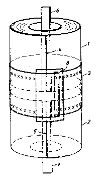
The accompanying drawing shows a preferred embodiment of the invention and
illuslrates how two stacked coils l and 2 can suitably be joined together with the
aid of a belt 3. It is also seen, as previously described, how the tail end of the
outermost layer of coil l terminals at 4, i.e. that the winding direction is
clocl;\~ise, and that coil 2 tcrminates at 5 and the winding direction is counter-
cloch-~hise. Coil 1 has a bar 6 as its inner terminal and the corresponding inner
terminal for coil 2 is a bar 7.
As mentioned above, the belt 3 consists of a thin strip, preferably of the same
material as the sheet-wound conducting material. The belt and the outer coil
laye~s can be effected in many different ways, such as ultrasonically or using
spot or seam welding. The joint is indicated by xxx in the drawing. The welded
ar~as of the belt to the outer coil layer must be sufficient to fulfil the require-
ment of sufficiently low transition resistance.
As is evident, the belt also forms an electrical screen for the edges of the coils
Iacing each other. To obtain full protection around the entire periphery a
certain peripheral overlapping of the belt is necessarv. To prevent this overlapfrom causing the belt to form a closed coil turn, the overlapping parts must be
electrically isolated. This is suitably achieved by placing an insulating strip g
between -the overlapping parts of the belt. The insulating strip should have such
peripheral extension that it more than covers the part of the belt which is not
joined to the outer coil layers.
The inner belt described earlier is applied in the same way as the exterior belt,
the belt being joined with overlap to the inner coil layers of the sheet-wound
coil, and with an insulating strip at the overlap. The external terminals of these
outer coils may then comprise bars connected to the coil ends terminating out-
side. There is normally always sufficient space for these outer terminals.

Representative Drawing
A single figure which represents the drawing illustrating the invention.
Administrative Status

2024-08-01:As part of the Next Generation Patents (NGP) transition, the Canadian Patents Database (CPD) now contains a more detailed Event History, which replicates the Event Log of our new back-office solution.

Please note that "Inactive:" events refers to events no longer in use in our new back-office solution.

For a clearer understanding of the status of the application/patent presented on this page, the site Disclaimer , as well as the definitions for Patent , Event History , Maintenance Fee  and Payment History  should be consulted.

Event History

Description Date
Time Limit for Reversal Expired 2003-07-02
Letter Sent 2002-07-02
Grant by Issuance 1996-05-07
All Requirements for Examination Determined Compliant 1995-01-16
Request for Examination Requirements Determined Compliant 1995-01-16
Application Published (Open to Public Inspection) 1992-02-08

Abandonment History

There is no abandonment history.

Fee History

Fee Type Anniversary Year Due Date Paid Date
MF (patent, 6th anniv.) - standard 1997-07-02 1997-06-26
MF (patent, 7th anniv.) - standard 1998-07-02 1998-06-22
MF (patent, 8th anniv.) - standard 1999-07-02 1999-06-30
MF (patent, 9th anniv.) - standard 2000-07-04 2000-06-23
MF (patent, 10th anniv.) - standard 2001-07-03 2001-06-19
Owners on Record

Note: Records showing the ownership history in alphabetical order.

Current Owners on Record
ASEA BROWN BOVERI AB
Past Owners on Record
ERIK FORSBERG
LENNART LUNDSTROM
UNO ZETTERLUND
Past Owners that do not appear in the "Owners on Record" listing will appear in other documentation within the application.
Documents

To view selected files, please enter reCAPTCHA code :


To view images, click a link in the Document Description column. To download the documents, select one or more checkboxes in the first column and then click the "Download Selected in PDF format (Zip Archive)" or the "Download Selected as Single PDF" button.

List of published and non-published patent-specific documents on the CPD .

If you have any difficulty accessing content, you can call the Client Service Centre at 1-866-997-1936 or send them an e-mail at CIPO Client Service Centre.


Document
Description 
Date
(yyyy-mm-dd) 
Number of pages   Size of Image (KB) 
Abstract 1995-08-16 1 51
Drawings 1994-05-20 1 13
Claims 1994-05-20 1 30
Description 1994-05-20 3 111
Abstract 1996-05-06 1 50
Description 1996-05-06 4 174
Claims 1996-05-06 1 39
Drawings 1996-05-06 1 16
Representative drawing 1998-07-29 1 9
Maintenance Fee Notice 2002-07-29 1 177
Fees 1996-06-20 1 65
Fees 1995-06-26 1 58
Fees 1994-06-27 1 60
Fees 1993-06-29 1 34
National entry request 1993-02-03 5 155
International preliminary examination report 1993-02-03 8 230
Prosecution correspondence 1995-01-22 2 52
Prosecution correspondence 1995-01-15 1 41
Correspondence related to formalities 1996-02-27 1 35
Courtesy - Office Letter 1995-02-07 1 49
Prosecution correspondence 1995-01-22 4 200
Prosecution correspondence 1993-02-03 7 345