Sélection de la langue

Search

Sommaire du brevet 2088914 

Énoncé de désistement de responsabilité concernant l'information provenant de tiers

Une partie des informations de ce site Web a été fournie par des sources externes. Le gouvernement du Canada n'assume aucune responsabilité concernant la précision, l'actualité ou la fiabilité des informations fournies par les sources externes. Les utilisateurs qui désirent employer cette information devraient consulter directement la source des informations. Le contenu fourni par les sources externes n'est pas assujetti aux exigences sur les langues officielles, la protection des renseignements personnels et l'accessibilité.

Disponibilité de l'Abrégé et des Revendications

L'apparition de différences dans le texte et l'image des Revendications et de l'Abrégé dépend du moment auquel le document est publié. Les textes des Revendications et de l'Abrégé sont affichés :

  • lorsque la demande peut être examinée par le public;
  • lorsque le brevet est émis (délivrance).
(12) Brevet: (11) CA 2088914
(54) Titre français: BOBINES A ENROULEMENT EN BANDE
(54) Titre anglais: SHEET-WOUND COILS
Statut: Périmé et au-delà du délai pour l’annulation
Données bibliographiques
(51) Classification internationale des brevets (CIB):
  • H01F 27/28 (2006.01)
  • H01F 41/10 (2006.01)
(72) Inventeurs :
  • FORSBERG, ERIK (Suède)
  • LUNDSTROM, LENNART (Suède)
  • ZETTERLUND, UNO (Suède)
(73) Titulaires :
  • ASEA BROWN BOVERI AB
(71) Demandeurs :
(74) Agent: ROBIC AGENCE PI S.E.C./ROBIC IP AGENCY LP
(74) Co-agent:
(45) Délivré: 1996-05-07
(86) Date de dépôt PCT: 1991-07-01
(87) Mise à la disponibilité du public: 1992-02-08
Requête d'examen: 1995-01-16
Licence disponible: S.O.
Cédé au domaine public: S.O.
(25) Langue des documents déposés: Anglais

Traité de coopération en matière de brevets (PCT): Oui
(86) Numéro de la demande PCT: PCT/SE1991/000471
(87) Numéro de publication internationale PCT: WO 1992002941
(85) Entrée nationale: 1993-02-04

(30) Données de priorité de la demande:
Numéro de la demande Pays / territoire Date
9002585-9 (Suède) 1990-08-07

Abrégés

Abrégé anglais


A procedure when joining the tail ends of sheet-wound coils (1, 2)
stacked one on top of the other around an inductive apparatus core with a
certain axial space between them, the joint being effected using a thin
leader strip (3) which is connected to adjacent parts of the coils and joined
to the coils along almost one coil turn.

Revendications

Note : Les revendications sont présentées dans la langue officielle dans laquelle elles ont été soumises.


The embodiments of the invention in which an exclusive
property or privilege is claimed are defined as follows:
1. A method of joining sheet-wound coils stacked one on
top of the other with an axial space therebetween
comprising:
- stacking a first coil having a top surface and a bottom
surface on top of a second coil having a top surface and a
bottom surface leaving a space between the bottom surface
of the first coil and the top surface of the second coil.
- wrapping a belt consisting of a thin leader strip having
a leading end and a tail end covering the bottom surface of
the first coil, the top surface of the second coil and the
space therebetween; and
- connecting the leader strip to the bottom surface of the
first coil and the top surface of the second coil along one
coil turn.
2. A method according to claim 1, wherein said leader
strip is made of the same material as the material of said
sheet-wound coils.
3. A method according to claim 1, wherein said leader
strip is sufficiently long that said leading end thereof
overlaps said tail end thereof.
4. A method according to claim 1, including the step of
inserting an insulating strip between said leading end and
said tail end of said leader strip.
5. A method according to claim 1, wherein said leader
strip is connected to said first and second coils by
ultrasonic welding.

Description

Note : Les descriptions sont présentées dans la langue officielle dans laquelle elles ont été soumises.

~ 0 8 ~
WO 92/02941 1 PCI/SE91/00471
Sheet wound coils
TECHNICAL FIELD
Transiormers are often provided with sheet-wound coils. A coil on an inductive
apparatus core may then consist of two or more wound part-coils stacked one on
top of the other, which must be joined together in some way. The present
invention comprises a procedure for achieving this.
BACIC~ROUND ART
Sheet-wound coils are often used as low-voltage coils and consequently conduct
rel~ively lligh curren~s. The output conductors must therefore be dimensioned
accordingly .
When two sheet-wound coils are stacked one on top of the other around a
common transformer core with a certain axial space between them, the two
sheet-wound coils are identical. However, they are stacked and joined in such a
way that, from the winding-direction point of view, they are directed towards
each other. This means, therefore, that if a current travels for an instant fromthc inner layer of one coil to its outer coil, the current from the outer layer of
the other coil will continue to the inner layer of the second coil.
It is thus the outer sheet layers of the coils that are joined, i.e. the exterior of
the coils. This requires space when electrically dimensionin~ the main channel
to the outer coil. It is therefore of great importance that a joint requires as
iittle space radially as possible.
Coils have previously been joined with the aid of a copper bar in the final turn.
If the area of sheet and bar is the same, with a sheet dimension of 0.5 x l000 mm
and bar width of 80 mm, for instance, the bar thickness will be 6.25 mm.
SUMMARY OF THE INVENTION
The invention permits connection of stacked coils without their having to be
provided with terminals. Each coil is wound approximately a half turn more than
is necessary in conventional bar splicing as described above. The coils shall be

2 20889 ~ 4
stacked with respect to winding direction in accordance
with the state of the art and shall also be arranged
radially so that their outer tail ends are located on a
generatrix substantially common to the coils.
According to the present invention there is provided a
method of joining sheet-wound coils stacked one on top of
the other with an axial space therebetween comprising:
- stacking a first coil having a top surface and a bottom
surface on top of a second coil having a top surface and a
bottom surface leaving a space between the bottom surface
of the first coil and the top surface of the second coil.
- wrapping a belt consisting of a thin leader strip having
a leading end and a tail end covering the bottom surface of
the first coil, the top surface of the second coil and the
space therebetween; and
- connecting the leader strip to the bottom surface of the
first coil and the top surface of the second coil along one
coil turn.
Therefore, the present invention comprises winding a thin
strip of conducting material around the coils and attaching
this in some suitable manner to the outer layer of the
coils along almost one coil turn. The equally large
portion of the coils' periphery which is not joined by the
thin strip prevent the short-circuiting of the coil layers.
The above-mentioned generatrix which coincides with the
tail ends of the coils is arranged to lie substantially
centrally in the unjoined portion.
The thin strip which thus joins the outer layers of the two
coils is dimensioned to ensure a sufficiently large contact
area between this and the outer coil layers and that the
current endurance will be at least the same as for the rest

2a 20889 1 ~
of the sheet-wound coil. The thickness of the thin
surrounding strip is 0.1 - 0.5 mm and therefore offers a
considerable saving in space in comparison with the current
state of the art
As mentioned, the stacked coils is spaced a certain
distance from each other in axial direction. The thin
strip wound around the coils also covers the channel formed
between the coils, like a belt. The be~t thus electrically
screens and protects the corners of the coils facing this
channel. To also protect the part of the corners in the
above-mentioned unjoined portion of the thin strip, this
strip is extended to overlap. However, insulating the
overlapping portion from the layer below, will prevent the
belt from forming a closed turn of the coil.
If now the coils located closest to a transformer core as
above constitute a part of a secondary winding, a
corresponding part of the primary winding will be located
outside these. Such a primary winding can also be
constructed as a sheet-wound coil. In order to take full
advantage of an exterior belt, the belt concept should also
be utilized as an inner belt for sheet-wound coils outside
the belt.
An inner belt can be joined to the coils inside it in the
same way as described for the outer coil layers. For the
same reason as above, an inner belt can be provided with
overlap and an insulation intermediate portion.

7~ WO 92/02941 ' 3 PCllSE91/~0471
2~89~ ~
l he procedure described offers considerable savings in space as well as higher
performance and efficiency than has been the case in previous procedures for
joining sheel-wound coils.
DESCRlPTlOl~i OF THE PREFERRE~ ~MBODIMENT
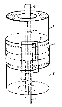
The accompanying drawing shows a preferred embodiment of the invention and
illuslrates how two stacked coils l and 2 can suitably be joined together with the
aid of a belt 3. It is also seen, as previously described, how the tail end of the
outermost layer of coil l terminals at 4, i.e. that the winding direction is
clocl;\~ise, and that coil 2 tcrminates at 5 and the winding direction is counter-
cloch-~hise. Coil 1 has a bar 6 as its inner terminal and the corresponding inner
terminal for coil 2 is a bar 7.
As mentioned above, the belt 3 consists of a thin strip, preferably of the same
material as the sheet-wound conducting material. The belt and the outer coil
laye~s can be effected in many different ways, such as ultrasonically or using
spot or seam welding. The joint is indicated by xxx in the drawing. The welded
ar~as of the belt to the outer coil layer must be sufficient to fulfil the require-
ment of sufficiently low transition resistance.
As is evident, the belt also forms an electrical screen for the edges of the coils
Iacing each other. To obtain full protection around the entire periphery a
certain peripheral overlapping of the belt is necessarv. To prevent this overlapfrom causing the belt to form a closed coil turn, the overlapping parts must be
electrically isolated. This is suitably achieved by placing an insulating strip g
between -the overlapping parts of the belt. The insulating strip should have such
peripheral extension that it more than covers the part of the belt which is not
joined to the outer coil layers.
The inner belt described earlier is applied in the same way as the exterior belt,
the belt being joined with overlap to the inner coil layers of the sheet-wound
coil, and with an insulating strip at the overlap. The external terminals of these
outer coils may then comprise bars connected to the coil ends terminating out-
side. There is normally always sufficient space for these outer terminals.

Dessin représentatif
Une figure unique qui représente un dessin illustrant l'invention.
États administratifs

2024-08-01 : Dans le cadre de la transition vers les Brevets de nouvelle génération (BNG), la base de données sur les brevets canadiens (BDBC) contient désormais un Historique d'événement plus détaillé, qui reproduit le Journal des événements de notre nouvelle solution interne.

Veuillez noter que les événements débutant par « Inactive : » se réfèrent à des événements qui ne sont plus utilisés dans notre nouvelle solution interne.

Pour une meilleure compréhension de l'état de la demande ou brevet qui figure sur cette page, la rubrique Mise en garde , et les descriptions de Brevet , Historique d'événement , Taxes périodiques et Historique des paiements devraient être consultées.

Historique d'événement

Description Date
Le délai pour l'annulation est expiré 2003-07-02
Lettre envoyée 2002-07-02
Accordé par délivrance 1996-05-07
Toutes les exigences pour l'examen - jugée conforme 1995-01-16
Exigences pour une requête d'examen - jugée conforme 1995-01-16
Demande publiée (accessible au public) 1992-02-08

Historique d'abandonnement

Il n'y a pas d'historique d'abandonnement

Taxes périodiques

Le dernier paiement a été reçu le 

Avis : Si le paiement en totalité n'a pas été reçu au plus tard à la date indiquée, une taxe supplémentaire peut être imposée, soit une des taxes suivantes :

  • taxe de rétablissement ;
  • taxe pour paiement en souffrance ; ou
  • taxe additionnelle pour le renversement d'une péremption réputée.

Veuillez vous référer à la page web des taxes sur les brevets de l'OPIC pour voir tous les montants actuels des taxes.

Historique des taxes

Type de taxes Anniversaire Échéance Date payée
TM (brevet, 6e anniv.) - générale 1997-07-02 1997-06-26
TM (brevet, 7e anniv.) - générale 1998-07-02 1998-06-22
TM (brevet, 8e anniv.) - générale 1999-07-02 1999-06-30
TM (brevet, 9e anniv.) - générale 2000-07-04 2000-06-23
TM (brevet, 10e anniv.) - générale 2001-07-03 2001-06-19
TM (demande, 2e anniv.) - générale 02 1993-07-01
Titulaires au dossier

Les titulaires actuels et antérieures au dossier sont affichés en ordre alphabétique.

Titulaires actuels au dossier
ASEA BROWN BOVERI AB
Titulaires antérieures au dossier
ERIK FORSBERG
LENNART LUNDSTROM
UNO ZETTERLUND
Les propriétaires antérieurs qui ne figurent pas dans la liste des « Propriétaires au dossier » apparaîtront dans d'autres documents au dossier.
Documents

Pour visionner les fichiers sélectionnés, entrer le code reCAPTCHA :


Pour visualiser une image, cliquer sur un lien dans la colonne description du document. Pour télécharger l'image (les images), cliquer l'une ou plusieurs cases à cocher dans la première colonne et ensuite cliquer sur le bouton "Télécharger sélection en format PDF (archive Zip)" ou le bouton "Télécharger sélection (en un fichier PDF fusionné)".

Liste des documents de brevet publiés et non publiés sur la BDBC .

Si vous avez des difficultés à accéder au contenu, veuillez communiquer avec le Centre de services à la clientèle au 1-866-997-1936, ou envoyer un courriel au Centre de service à la clientèle de l'OPIC.


Description du
Document 
Date
(aaaa-mm-jj) 
Nombre de pages   Taille de l'image (Ko) 
Page couverture 1994-05-21 1 14
Abrégé 1995-08-17 1 51
Dessins 1994-05-21 1 13
Revendications 1994-05-21 1 30
Description 1994-05-21 3 111
Page couverture 1996-05-07 1 18
Abrégé 1996-05-07 1 50
Description 1996-05-07 4 174
Revendications 1996-05-07 1 39
Dessins 1996-05-07 1 16
Dessin représentatif 1998-07-30 1 9
Avis concernant la taxe de maintien 2002-07-30 1 177
Taxes 1996-06-21 1 65
Taxes 1995-06-27 1 58
Taxes 1994-06-28 1 60
Taxes 1993-06-30 1 34
Demande d'entrée en phase nationale 1993-02-04 5 155
Rapport d'examen préliminaire international 1993-02-04 8 230
Correspondance de la poursuite 1995-01-23 2 52
Correspondance de la poursuite 1995-01-16 1 41
Correspondance reliée aux formalités 1996-02-28 1 35
Courtoisie - Lettre du bureau 1995-02-08 1 49
Correspondance de la poursuite 1995-01-23 4 200
Correspondance de la poursuite 1993-02-04 7 345