Note: Descriptions are shown in the official language in which they were submitted.
2088940
CONDENSATE DISCIIARCINC DEVICE
BACKGROUND OF THE INVENTION
1. Field oJ the Invention
The present invention relates to a condensate
discharging device for discharging condensate produced in
various kinds of equipmenl using s~eam and piping for slcam
or for feeding the condensate under pressure to a boiler or
an apparatus using waste heat.
2. Description of the Prior Art
Condensate condensed in equipment using steam is
ordinarily discharged through a steam trap. However in the
case where the condensale is recovered to a place higher in
pressure such as a boiIcr or an apparalus ulilizing wasle
heat or in the case where lhe secondary pressure is higher
~han the primary pressure like lhe case of discharging
condensate within a vacuum into the atmosphere the
condensate can not be discharged using the steam trap.
In the case where the secondary pressure is higher than
the primary pressure a condensate discharging device
(pumping trap) as disclosed in Japanese utility model
laid-open publication sho-50-147228 is used. This device
comprises a condensate receiving chamber provided wilh a
2088940
condensale inlel opening and a condensale oullel opening, and
a high pressure operaling fluid (pressure gas) inlel and
oullel. In lhe condensale receiving chamber, an open or
closed type of floal is sel up so as to rise and drop
5 according to the water level and is connected lo an inlel
valve for opening and closing the operating high pressure
fluid inlet and lo an exhausl valve for opening and closing
the fluid outlel. Through lhe cooperalion wilh respeclive
check valves arranged al lhe condensale inlet and oullet
lo openings, condensale is inlroduced inlo lhe condensale
receiving chamber, afler lhe operaling high pressure fluid
inlel is closed and lhe fluid oullel is opened, unlil lhe
water Ievel within the condensale receiving chamber reaches a
predetermined level. When lhe predelermined level is reached,
15 the operaling high pressure fluid outlel is closed and lhe
fluid inlel is opened, inlroducing lhe operating bigh
pressure fluid inlo lhe condensale receiving chamber so lhal
the aclion of pressure causes lhe condensale lo be discharged
Irom the opened outlel opening.
Furthermore, U.S. palenl No. 5,141,405 discloses a
device basically similar in conslruclion lo lhe
above-described device.
Among lhe above-mentioned devices using steam, lor
- 2 -
2088940
example in a heal exchanger for hcaling a fluid lo be healed
by slcam supply lo lhc hcal cxchangcr is carricd out aftcr
the pressure of sleam is controlled so as to mainlain a
temperature of lhe fluid lo be heated delivered Irom the heal
exchanger constanl which causes the primary pressure to rise
to a pressure higher or fall to a pressure lower than Ihe
secondary pressure.
If thc condensate discharging device disclosed in lhe
above-menlioned ulilily model laid-open publication sho-
lo 50-147228 or U.S. patcnt No. 5 141 405 is mounled on such a
piece of equipment using steam a problem arises in that when
the primary pressure rises lo a pressure higher than the
secondary pressure thc check valve arranged at the
condensale oullet is always caused to be opened so that not
only the condensale but also the steam under high pressure is
flown oul lhere~hrough. Meanwhile if an ordinary sleam lrap
is mounted on such a device using steam it will not be able
to be used in the case where the primary pressure is lower
than the secondary pressure.
SUMMARY 0~ THE INVENTION
An object of the invention is therefore to provide a
condensate discharging device which enables only condensate
- 3 -
2088940
-
lo be discharged or fcd under pressure withoul leaking out
sleam independenlly of lhe respeclive pressures at lhe
primary side and al lhe sccondary side.
To achieve the above-mentioned object, according to the
S presenl invention, lhere is provided a condensale discharging
device comprising a condensale receiving chamber provided
with a condensate inlet opening and a condensate outlet
opening as well as an operating high pressure fluid inlel and
outlet; a float of open or closed lype disposed within said
condensate receiving chamber and adapted lo rise and drop
along with the water level; an inlet valve connecled lo said
floal and used for opcning and closing said fluid inlet; an
exhaust valve connected to said float and used for opening
and closing said fluid oullet; check valves, one arranged al
~5 said condensale inlet opening and the olher at said
condensate oullel opening; and a valve means connected to
said float to open and close said condensate outlet opening
independently of said check valves, said valve means being
adapted to close said condensate outlet opening when the
water level in said condensa~e receiving chamber is low, and
to open said oullet opening when lhere is a rise in lhe waler
level, whereby after said float closes said fluid inlet and
opens said fluid outlel, the condensate is introduced from
20889~0
said condensate inlet opcning inlo said condensate receiving
chamber, unlil thc walcr level in said condcnsale rcceiving
chamber reaches a predelermined waler level, and said fluid
outlet is closed and said fluid inlet is opened, the
condensate thereby being discharged from the opened
condensate outlet opening when said predetermined water level
is reached.
The operation of the above-mentioned condensate
discharging device is as follows.
In the case where the primary pressure is lower than the
secondary pressure, the check valve arranged at the
condensate outlet opening and the inlet valve for opening and
closing the operating high pressure fluid inlet are closed,
and the check valve arranged al lhe condensale inlel opening
and lhe exhaust valve for opening and closing the exhausl
oullet are opened, unlil lhe waler level in lhe condensale
receiving chamber reaches a predetermined water level.
Condensate is flown from the condensate inlet opening into
the condensate receiving chamber and the float rises along
with the rise in the water level. The rise of the float
causes the valve means connected to the float to open the
condensate outlet opening, but the check valve arranged at
the condensate outlet opening keeps the valve closed. When a
2088940
predetermined waler Ievel is reached in lhe condensale
receiving chamber lhe inlet valve is opened and the exhaust
valve is closed. The operating high pressure fluid
introduced from the fluid inlet brings aboul a rise of the
S pressure in lhe condensale receiving chamber causing lhe
check valve al Ihe condensate oullel opening to open and
discharging condensale from the condensa~e ou~le~ opening.
The float drops along with the fall in the water level due lo
discharge of condensale and when it drops to a Predetermined
position the inlet valve is closed and the exhaust valve is
opened. Furthermore the valve means closes the condensate
outlet opening and at lhe same lime the check valve at the
condensate oullel opening is closed lo slop the discharge of
condensate. This operalion is recycled so that tlle storage
and discharge of condensate is repeated.
In lhe case where lhe primary pressure is higher than
the secondary pressure the respective check valves arranged
at the condensate inlet and outlet openings are opened. The
float rises and drops according to the water level in the
condensate receiving chamber so that the valve means closes
and opens lhe condensate oullet opening ~hereby discharging
condensate therefrom.
208~940
BRIEF DeSCRllTlON 01 TIIE DRAWINGS
The above and olher objects and fealures of the
invention will be more apparent upon a reading oI the
following detailed specification and drawings in which:
Figs. 1 to 4 are sectional views of a condensate
discharging device according to one embodiment of the
invention and showing the state of operation when the primary
pressure is lower lhan the secondary pressure.
Fig. 1 is a sectional view showing the condition where a
float is at the uppermost position;
Fig. 2 is a sectional view showing the condition where
the float is at the lowermost position;
Fig. 3 is a sectional view showing the condition where
the Jloat is at the middle position and immediately before
condensate is discharged;
Fig. 4 is a sectional view showing the condition where
the float is at a middle position and condensate is being
discharged; and
Fig. 5 is a sectional view corresponding to Fig. I of a
condesate discharging device according to another embodiment
of the invention.
DETAILED DESCRIPTION OF PREFERRED EMBODIMENTS
2088940
Now the invention will be described in detail by way of
embodimenls wilh reference lo lhc drawings showing lhe
embodiments of the above-mentioncd lechnical means.
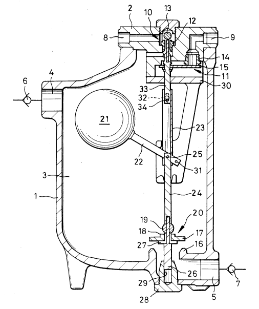
Referring to Fig.l a condensale discharging device
comprises a body 1 wilh a lid 2 mounted thereon by means of
bolls (nol shown) lhe inner hollow porlion formed thereby
being called a condensale receiving chamber 3. The body 1 is
formed al lhe upper porlion lhereof wilh a condensale inlel
opening 4 communicating with lhe condensate receiving chamber
3 and al the lowcr porlion lhereof wilh a condensale oullel
opening 5. Check valves 6 and 7 are provided al the inlel
opening 4 and the outlet opening 5 respectively. The lid 2
is formed with an inlel 8 and an ou~let 9 for an operaling
high pressure fluid. The inlel 8 communicales wilh lhe
condensale receiving chamber 3 lhrough an inlel valve 10 and
lhe outlel 9 communicates wilh lhe condensate receiving
chamber 3 through an exhaust valve 11. The inlet valve 10
consisls of an inlel valve seal 12 and an inlel valve body 13
which comes into and out or seating engagemenl with the inlet
valve seat 12 to thereby close and open the inlet valve 10.
The exhaus~ valve 1I consisls of an exhausl valve seat 14 and
an exhaust valve body 15 which comes in~o and oul of sealing
engagement with the exhaust valve seat 14 to thereby close
2088940
-
and open the exhaust valve 11. A main valve seat 16 is
formed on lhe end uf llle condensate outlel opening 5 wllich
opens toward the condensate receiving chamber 3. A main
valve body 17 which comes into and ou~ of seating engagemen~
with the main valve seat 16 to thereby close and oPen the
main valve is disposed within the condensate receiving
chamber 3 and is formed on the center portion thereof with a
sub-valve seat 18 above whicll a sub-valve body 19 which is
brought into and out of engagement with the sub-valve seat 18
lo to close and open the sub-valve is disPosed. The main valve
seat 16 and lhe main valve body 17 as well as lhe sub-valve
seal 18 and the sub-valve body 19 constitute a valve means 20
for closing and opening the condensate outlet opening 5.
A closed type of float 21 which rises and drops along
with the water level is housed within tlle condensate
receiving chamber 3. A Iever 22 is secured at one end
thereof to the float 21 and connected at the other end by
means of a pin 25 to a connecting member 23 of a channel-like
cross section extending uPwardly and a float shaft 24
extending downwardly. A stepped guide rod 26 is threadably
connected to the lower end of the float shaft 24. A
plurality of L-shaped guide ribs 27 are formed integrally
with the guide rod 26 on the lower region of the portion
20889~0
which has the smaller diameler down the float shaft 24 and,
at the same lime, a sub-valve body 19 is fitled on lhe
portion of the guide rod 26 having a smaller diameter between
the guide ribs 27 and lhe threaded connection, so that the
float sha(t 24, the guide rod 26, the sub-valve body 19 and
the guide ribs 27 are formed like one piece. The main valve
body 17 is slidably provided along the guide ribs 27 between
the sub-valve body 19 and the supporting portion of the
plurality of the guide ribs 27. The center hole of the main
valve body 17 is somewhat larger in diameter than the portion
of the guide rod 26 with the smaller diameter. As a result,
when the sub-valve body 19 is brought into engagement with
the sub-valve seat 18 formed on the peripheral edge of the
center hole of lhe main valve body 17, the communicating
spaces belween lhe adjacent guide ribs 27 are closed, and
when the sub-valve body 19 and the sub-valve seat 18 are
moved away from each other and the main valve body 17 is
supported by the supporling porlion of the guide ribs 21, the
condensate receiving chamber 3 and the condensate outlet
opening 5 communicate with each other through the above
-mentioned spaces. The lower portion of the guide rod 26 is
guided by the center guide hole 29 of a plug 28 threadably
connected to the body 1.
- 10-
2~)8~940
In the middle portion of lhe device, the ~ront end of a
lever 22 is rotatably connected by a pin 31 to a mounting
member 30 secured to the lid 2. The pin 31 constitutes a
fulcrum of the float 21. The connecting member 23 is
provided at the upper end thereof with the free space 32
shown with a dotted line, and a pin 34 is attached to a valve
stem 33 connected to an exhaus~ valve body 15 and loosely
fitted in and connected to the free space 32.
Now, operation of the device will be explained with
reference to Figs. 1 to 4.
In the case where lhe primary pressure on the check
valve 6 disposed at the condensate inlet opening 4 is lower
than the secondary pressure on the check valve 7 disposed at
the condensale outlet opening 5, the check valve 6 is opened
t allow condensate to flow into the condensate receiving
chamber 3, in the condition shown in Fig. 2. At this moment,
the float 21 is at the lowermost position and the inlet valve
10 is closed and the exhaust valve 11 is opened on account of
the re lal ion in position between lhe connecting member 23
connected to the float 21 through the lever 22 and the valve
rod 33. Furthermore, the valve means 20 is closed on account
of the relation in position of the float shaft 24 connected
to the float 21 through the lever 22.
2088940
Following the rise in lhe waler level due lo the inflow
of condcnsalc, thc floal 2l riscs, causing lhe conncctinK
member 23 and the floal shafl 24 lo be moved upwardly. As
the floal shafl 24 rises, lhe sub-valve body 19 is moved
upwardly together with the guide rod 26 away from the
sub-valve seat 18 to thereby open the sub-valve, and the
pressure in the lower space of the valve means 20 becomes
equal to that in lhe condensale receiving chamber 3 and,
accordingly, to the primary pressure in the check valve 6.
At this time, because of the higher secondary pressure, the
check valve 7 at the condensate outlet opening 5 is
maintained in the closcd condition.
Upon further rising of the float 21, the supporting
portion of the guide ribs 27 lifts up the main valve body 17
away from the main valve seat 16, as shown in the lower
region of Fig. 3, so thal ~he valve means 20 is entirely
brought inlo a valve opening condilion and lhe condensale
outlet opening S can be opened, but the check valve 7 is
still main~ained in Ihe close d condition.
The buoyance of the float 21 acts on the valve stem 33
from the moment when the float 21 rises to a predetermined
position and the lower end in the free space 32 of the
connecting member 23 comes into contact with the pin 34 of
- 12-
2088940
.
~he valve stem 33 (Fig. 3). When lhe water level increases
and the float rises lo a higher posilion, lhe valve slem 33
also rises to lift up the inlet valve body 13 away from the
inlet valve seat 12, thereby opening the inlet valve 10.
Meanwhile, the exhaust valve body 15 comes into seating
engagement with the exhaust valve seal 14, thereby closing
lhe exhausl valve 11, as shown in Fig. 1.
The opened condilion of lhe inlel valve 10 and the
closed condition of the exhaust valve 11 cause an operating
high pressure fluid lo flow from the inlet 8 through the
inlet valve 10 into lhe condensate receiving chamber 3, so
that the pressure in lhe condensale receiving chamber 3 is
increased lo close the check valve 6. When lhe pressure in
lhe condensale receiving chamber 3 becomes higher lhan lhe
secondary pressure on the check valve 7, the latter is opened
and condensate is discharged from lhe condensale oullel
opening 5.
According to a drop in the water level due to the
discharge of condensale, lhe floal 21 drops, causing the
connecling member 23 and the floal shafl 24 lo be moved
downwardly, and accordingly, lhe valve means 20 starts to
move towards a valve closing condition. As shown in Fig. 4,
lhe valve slem 33 is caused lo be moved downwardly from lhe
20~8940
moment when lhe floal 21 drops lo a predclermined posilion
and the upper cnd of thc frce space 32 comes inlo conlact
with the pin 34 to thereby actuale lhe sclf-weight of the
lloat 21 on the valve stem 33. The downward motion of the
valve slem 33 causes the inlet valve 10 lo be closed and lhe
exhausl valve 11 lo be opened. The closed condilion ol lhe
inlel valve 10 and the opened condition ol the exhaust valve
11 cause the pressure in the condensate receiving chamber 3
to be gradually decreased, and the discharge of condensate is
carried out by the residual pressure.
Upon further dropping of the float 21, the main valve
body 17 comes inlo sealing engagement wilh the main valve
seat 16 to thereby close the main valve. At the moment of
engagemenl, lhe sub-valve body 19 does nol come inlo sealing
engagemenl wilh lhe sub-valve seal 18, and lherefore,
condensate can be discharged from the communicating spaces
between the adjacent guide ribs 27. Shortly, the sub-valve
body 19 comes into seating engagement with the sub-valve seal
18, and thus, the entire valve means 20 closes the condensate
outlet opening 5, causing the check valve 7 to be closed and
returning to the condition of Fig. 2, in which the discharge
of condensate is stoPped. Then, the above-mentioned cycle is
repeated.
- 14 -
21)88910
.
In the case where the primary pressure is higher than
the secondary pressure both llle check valve 6 and lhe check
valve 7 can easily be brough~ into a valve opening condition
in the condition of the dcvice as shown in Fig. 2. When
S condensate flows from the condensate inlet opening 4 into Ihe
condensate receiving chamber 3 the float 21 rises as thc
water level rises and accordingly the connecting member 23
and the float sha[t 24 are moved upwardly. The upward molion
of the float shaft 24 causes the sub-valve body 19 to be
moved away from the sub-valve seat 18 so that condensate is
discharged through the communicating spaces bctween the
adjacent guide ribs 27. A [urther rise of the float 21 due
to an increased amounl of condensate causes the main valve
body 17 to be movcd away from thc main valve seat 16 thereby
1S discharging a large quantity o[ condensate through the
condensate outlet opening 5. Depending upon the velocity of
inflow of condensate into the condensate receiving chamber 3
a rise of the float 21 bringing about an upward motion of the
valve stem 33 through the connccting member 23 causing the
inlet valve body 13 to be lifted up to thereby allow an
operating high prcssure fluid to flow into the condensale
receiving chamber 3 can also occur. In this case the
operating high pressure fluid enhances the discharge of
- 15 -
20~89~0
-
condensate, and also permils adjuslmenl of lhe condilion of
opening lhe check valve 6 depending upon the degree ol
pressure thereof.
The floa~ 21 drops along with a fall of the water level
due to lhe discharge of condensale, and first, the main valve
body 17 comes inlo seating engagement with the main valve
seat 16. Then, the sub-valve body 19 also comes in~o seating
engagemenl wilh lhe sub-valve seal 18, so lhal lhe valve
means 20 is closed, thereby causing the condensate outlel
opening 5 to be closed.
Fig. 5 shows another embodiment in which the position of
the float corresponds lo lhal of Fig. 1. The conslruclion of
an entire condensate discharging device is basically
identical lo lhal of lhe above-menlioned embodiment, and the
device in question comprises lhe condensate receiving chamber
3; lhe inlel valve 10 and lhe exhausl valve 11 for an
operating high pressure fluid arranged above lhe condensale
receiving chamber 3; the condensate inlet opening 4; the
condensate outlet opening 5; and the valve means for
discharging condensate. The explanation of lhe parts common
to those of the previously described embodimenl is omitled
with like parts given like reference characters for
simplification of explanation, and herein, the construction
- 16 -
2088940
of the valve means differenl from lhe previously described
embodimenl and lhe operalion of lhe device will bc dcscribed.
The condensate receiving cbamber 3 is formed al lhe
lower end lhereof wilh an opening 40 which is closed wilh a
lower lid 41 altached by means of bolts (not shown). An
upper valve seal member having an upPer valve seal 42 al lhe
upper end lhereof is disposed belween the opcning 40 and lhe
lower lid 41 and al lhe same lime a lower valve seal member
having a lower valve seal 43 al lhe upper end thereof is
10 screwed inlo the inside lower portion of the upper valve seat
member. The uppcr and lower valve seat members are retained
by the lower lid 41.
In the region ranging from the upper valve seat mcmber
lo the lower valve seal member a stepped valve stem tube 47
is attached to the lower portion of the stePped floal shaft
24 connected to the floal 21 through the lever 22 in a
manner concentric with lhe float shalt 24. The Iloat shalt
24 extends lhrough lhe valve slem tube 47 with a clearance 49
lell lherein and has al lhe lower cnd a nul 50 lhrcadably
20 connected thereto.
An upper valve body 44 adapled to come into and out of
engagement with an upper valve seat 42 and a lower valve body
45 adapted to come into and out of engagement with a lower
2o8894o
valve seat 43 are mounled on lhe ouler periphery of the valve
stem lube 47 through a connecling tube 46 lherebetween, and
are fixed by a nul 48 lhrcadably connecled to lhe lower end
of the valve slem tube 41, wilh lhe upper end ol lhe upper
valve body 44 and lhe upper end ol lhe valve slem tube 47 in
abutting engagement wilh the slep of the valve stem tube 47
and the step of the lloal shafl 24, respeclively. The upper
valve seat 42, upper valve body 44, lower valve seat 43 and
lower valve body 45 constitute a composite seat valve.
lo The upper and lowcr valvc bodies 44 and 45 are provided with
a plurality of vanes, respectively, which are used to guide
the upper and lowcr valvc scal membcrs.
The valve slem shafl 47 is provided at the upper and
lower portions lhereof with through holes 51 and 52,
respectively, so that the condensate receiving chamber 3 and
the space underneath lhe lower valve body 45 communicale wilh
each other through the clearance 49. This construction
reduces the influencc on lhe operalions lor opening and
closing the valve due to a dilference in pressure.
In the case where the primary pressure on the check
valve 6 arranged at the condensate inlet opening 4 is lower
than the secondary pressure on the check valve 7 arranged at
the condensate oullel opening 5, lhe check valve 6 at lhe
- 18 -
20889~o
inlet opening 4 is opened and allows condensate to flow into
lhe condensale receiving chamber 3. Al this lime, lhe float
21 is at lhe lowermost position, and the inlet valve 10 is
closed and the exhausl valve 11 is opened on account of the
relation in position of the connecting member 23 and valve
stem 33 connected lo the float 21 through the lever 22.
Moreover, the upper and lower valve bodies 44 and 45 are
brought into seating engagement the upper and lower vaIve
seals 42 and 43, respeclively, on account of the relation in
posilion of lhe float shafl 24 connecled to the float 21
through the lever 22.
Along with the rise in the water level due to inflow of
condensate, the float 21 rises, causing the connecting membe-
23 and the float sbaft 24 to rise. As the float shaft 24
rises, the composite seat valve also rises, causing the uPper
valve body 44 and the lower valve body 45 to be
simultaneously disengaged from the upper valve seat 42 and
the lower valve seat 43, respectively, to thereby open the
comPosile seal valve, so lhal lhe pressure in the space
between lhe opening 40 and lhe lower lid 41 becomes equal lo
thal in the condensate receiving chamber 3, and accordingly,
the primary pressure on ~he check valve 6. At lhis moment,
since the secondary pressure is higher than the primary
- 19-
2n889qo
pressure, lhe check valve 7 al lhe oul let opening 5 is kepl
closed.
The buoyance of ~he floal 21 acts on lhe valve slcm 33
from thc momenl when thc floal 21 rises lo a predelermincd
S posilion and the lower end in the free space 32 of the
connecting member 23 comes into contact with the pin 34 of
the valve stem 33. When the water level rises and the float
21 reaches a higher posilion, Itle valve stem 33 also rises,
causing the inlet valve body 13 to be lifted up away from the
inlet valve seat 12 so that the inlet valve 10 is opened. In
the meanwhile, the exhaust valve body 15 comes into seating
engagement with the exhaust valve seat 14 to thereby close
the exhaust valve 11, as shown in Fig. S.
The opened condition of ttle inlet valve 10 and lhe
closed condition of the exhaust valve 11 cause the operating
high pressure fluid to flow from the fluid inlet 8 through
the inlet valve 10 into the condensate receiving chamber 3,
thereby bringing about the rise in pressure within the
condensate receiving chamber 3 to close the check valve 6.
When the pressure within the condensate receiving chamber 3
becomes higher than the secondary pressure on lhe check valve
7, the check valve 7 is opened to allow condensate to be
discharged from the outlet opening 5.
- 20 -
2088940
Along with a drop in the water level due to the
discharge of condensate the float 21 drops causing the
connecting member 23 and lhe floal shafl 24 to move
downwardly through thc Icvcr 22 toward lhe closing condition
of the composile valve. The valve stem 33 is caused to move
downward from the moment when lhe float 21 drops to a
predetermined posilion and lhe upper end in lhe free space 32
comes into abutting engagemenl with the pin 34 so thal the
self-weight of the. float 21 acts on the valve stem 33. The
downward motion of the valve stem 33 shortly causes the inlet
valve 10 to be closed and the exhaust valve 11 to be opened.
The closed condition of the suclion valve 10 and lhe opencd
condition of the exhaust valve 11 cause the pressure within
the condensate receiving chamber 3 lo be gradually decreased
so that the discharge of condensate is carried out under the
residual pressure.
Further dropping of the float 21 causes the upper valve
body 44 and the lower valve body 45 to come into seating
engagement with the upper valve seat 42 and the lower valve
seat 43 respectively to close the composite seat valve so
that the outlet opening 5 is closed causing the check valve
7 at the outlet opening 5 to be closed and the discharge of
condensate is stopped. Thus the above-mentioned cycle is
20889~0
repeated.
In the case wherc ~he primary pressure is higher lhan
the secondary pressure, both the clleck valves 6 and 7 can be
easily opened together. When condensate flows from the inlet
S opening 4 into the condensate receiving chamber 3, the water
level rises, causing the Iloal 21 ~o rise to thereby move
upwardly the connecting member 23 and the float shaft 24
through the lever 22. The rise of lhe floal shafl 24 causes
the upper valve body 44 and the lower valve body 45 to be
disengaged from the upper and lower valve seats 42 and 43,
respectively, to thereby discharge condensate from the outlet
opening 5. Depending upon the velocity of inflow of
condensate into the condcnsate receiving chamber 3, the
buoyancy of the float 21 bringing about the rise of the valve
stem 33 through the connecting member 23, thereby forcing the
inlet valve body 13 upwardly to make the operating high
pressure fluid to flow into the condensate receiving chamber
3, can occur. In this case, the operating high pressure
fluid enhances the discharge of condensate, and the opening
condition of the check valve 6 may be also adjusted depending
upon the degree of pressure.
Along with a drop in the water level due to the
discharge of condensate, the float 21 drops, causing the
- 22 -
2V88940
upper valve body 44 and lhe lower valve body 45 to comc into
seating engagemenl wilh lhe upper valve seal 42 and thc lower
valve seat 43, respectively, to close the composile seal
valve so thal the oullel opening 5 is closed.